Root Cause Analysis: Primary Causes of Butterfly Valve Leakage in Industrial Systems
March 20, 2026
Home+Root Cause Analysis: Primary Causes of Butterfly Valve Leakage in Industrial Systems
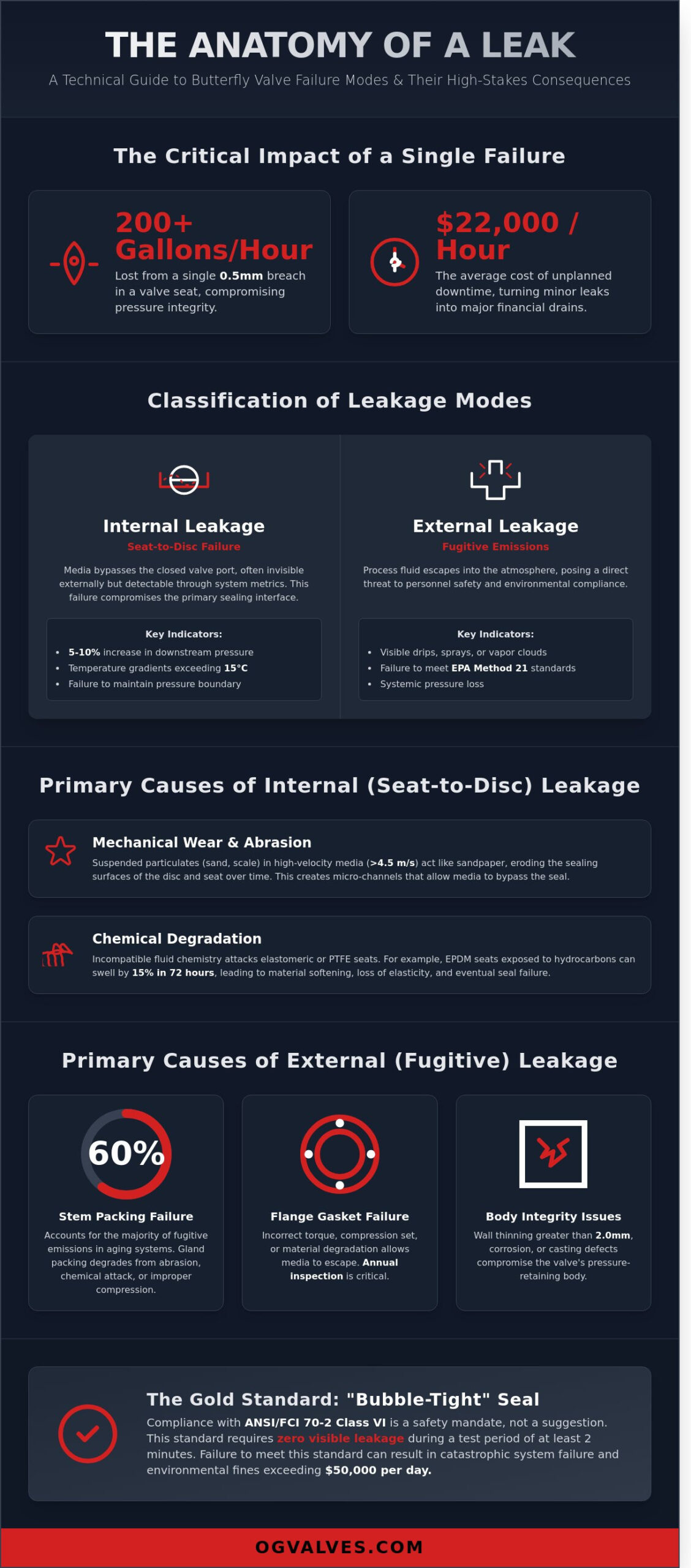
In high-pressure industrial environments, a single 0.5-millimeter breach in a valve seat can result in over 200 gallons of medium bypass per hour. You’re aware that maintaining pressure integrity isn’t just a maintenance goal; it’s a safety mandate where unplanned downtime costs an average of $22,000 per hour. Identifying the specific causes of butterfly valve leakage requires more than a visual inspection. It demands a clinical evaluation of the mechanical and chemical factors at play. This technical analysis provides a rigorous examination of internal and external leakage pathways, focusing on how material degradation and mechanical misalignment compromise ISO 5208 compliance standards. By analyzing API 609 dimensional tolerances and elastomer compatibility, we address the systemic failures that often bypass routine maintenance schedules.
We’ll provide a root cause framework for assessing seat wear, stem seal failure, and common specification errors that lead to premature component fatigue. This report establishes a technical foundation for you to refine your procurement standards and ensure long-term performance in critical oil, gas, or water treatment infrastructure. Through this detailed examination of failure modes, you’ll gain the necessary data to mitigate safety risks associated with fugitive emissions and medium bypass in high-pressure systems.
Key Takeaways
Distinguish between internal bypass and external fugitive emissions to accurately diagnose systemic failures and maintain “bubble-tight” seal integrity.
Analyze the primary causes of butterfly valve leakage, focusing on how mechanical wear and chemical incompatibility compromise seat-to-disc performance.
Evaluate the impact of environmental stressors such as cavitation and high-pressure drops on material selection for critical infrastructure.
Identify the mechanical precursors to stem and body leakage, specifically the role of abrasive particulates in gland packing degradation.
Implement technical mitigation strategies and Root Cause Analysis (RCA) frameworks based on API 609 and ISO 5208 industrial standards.
Classification of Butterfly Valve Leakage Modes
The industrial integrity of a Butterfly valve depends on its ability to maintain a pressure boundary under rigorous operational conditions. Engineers classify leakage into two distinct categories: internal and external. Identifying the specific causes of butterfly valve leakage requires a clinical assessment of the valve’s mechanical state. Internal leakage involves the bypass of media through the valve port when the valve is in the closed position. External leakage refers to the escape of process fluids into the atmosphere through the stem or body joints. Both failure modes compromise system efficiency and safety protocols.
In critical infrastructure, the requirement for a “bubble-tight” seal, defined by ANSI/FCI 70-2 Class VI, isn’t a suggestion but a safety mandate. This standard specifies that there should be no visible leakage during a test period of at least 2 minutes. Achieving this level of precision is vital for high-stakes sectors like oil and gas, where even a 0.5% loss in pressure can signal a systematic breakdown. Distinguishing between minor seepage, which might involve a rate of 0.1 mL per minute, and catastrophic mechanical failure is essential for predictive maintenance. While seepage might indicate early-stage seat wear, catastrophic failure leads to immediate depressurization and potential environmental non-compliance.
The impact of leakage extends beyond simple fluid loss. It directly affects system pressure stability, operational safety, and adherence to environmental regulations such as ISO 14001. A failure to contain the medium can result in fines exceeding $50,000 per day in strictly regulated jurisdictions. Maintaining the integrity of these valves is the only way to ensure the long-term performance of the entire fluid control network.
Internal Leakage: Seat-to-Disc Failure
Internal leakage occurs when the disc fails to achieve a positive seal against the resilient or metal seat. This bypass through the valve port is often invisible from the outside but reveals itself through downstream pressure spikes. Technicians often detect this through a 5% to 10% increase in downstream pressure or localized temperature gradients exceeding 15 degrees Celsius. These variances indicate that the causes of butterfly valve leakage are likely related to seat erosion or disc misalignment. Internal leakage is the failure of the primary sealing interface to isolate the medium.
External Leakage: Stem and Body Integrity
External leakage poses a direct threat to personnel safety and environmental compliance. Fugitive emissions at the stem packing or gland interface are the most common culprits, often failing to meet EPA Method 21 standards. Leakage also occurs at the body-to-bonnet joint or the flange connections if the torque specifications aren’t met. The role of O-rings and gaskets is critical here; these components must withstand pressures up to 150% of the valve’s rated capacity to maintain the external pressure boundary. High-performance valves utilize secondary seals to prevent the escape of hazardous media even if the primary packing fails.
Stem Packing: Responsible for 60% of external fugitive emissions in aging systems.
Flange Gaskets: Must be inspected every 12 months for signs of compression set.
Body Integrity: Requires ultrasonic testing if wall thinning exceeds 2.0 mm from original specifications.
Primary Causes of Internal (Seat-to-Disc) Leakage
Internal leakage occurs when the seal between the disc edge and the valve seat fails, allowing media to bypass the valve in the closed position. This failure often stems from mechanical wear or abrasion. In systems where media velocity exceeds 4.5 meters per second, suspended particulates like sand, scale, or catalyst fines act as an abrasive medium. Over time, these particles erode the sealing surfaces of both the disc and the seat, creating micro-channels that compromise the valve’s shut-off integrity. This is one of the most frequent causes of butterfly valve leakage in mining and wastewater applications.
Chemical degradation represents another significant threat to seal integrity. When elastomeric or PTFE liners are exposed to incompatible fluid chemistry, the material properties change at a molecular level. For example, exposing an EPDM seat to hydrocarbon-based fluids can result in a 15% volume increase within 72 hours. This swelling increases the required operating torque and eventually leads to material tearing or “bubbling.” Conversely, chemical attack can cause hardening, where the seat loses the elasticity required to maintain a bubble-tight seal under API 598 testing standards.
Mechanical deformation is frequently caused by the application of excessive torque. If an actuator isn’t properly sized or if an operator uses a “cheater bar” on a manual gear operator, the force can exceed the 250 MPa yield strength of the seat material. This results in permanent deformation of the disc edge or the seat housing. Additionally, the accumulation of debris like weld slag or calcium carbonate scaling prevents the disc from reaching its full 90-degree closure. Even a 2mm deposit on the seat prevents the uniform compression needed for a zero-leakage seal.
Soft Seat vs. Metal Seat Failure Modes
Resilient seats are prone to compression set, a condition where the synthetic rubber loses its ability to return to its original shape after prolonged closure. After 8,000 cycles, many EPDM or Viton seats show a measurable loss in rebound, leading to bypass. Thermal cycling between 10°C and 150°C accelerates this hardening and cracking. In contrast, metal-to-metal seats face galling. Without a hardfacing material like Stellite 6, high-pressure friction causes metal transfer between the disc and seat, destroying the precision-machined finish required for Class IV or VI leakage rates.
Disc Interference and Misalignment
Structural integrity issues often manifest as disc misalignment. A detailed butterfly valve pressure analysis indicates that high pressure differentials cause measurable shaft deflection. This bending force shifts the disc into an eccentric position, causing it to strike the seat unevenly. If the actuator’s limit switches aren’t calibrated within a 0.5-degree tolerance, the disc won’t reach the neutral sealing point. Furthermore, thermal expansion differentials in cryogenic or high-heat service can cause the disc to expand at a different rate than the valve body, leading to binding or localized gaps in the seal. Ensuring your system uses precision-engineered valve components can mitigate these alignment risks in critical infrastructure.
Root Causes of External Stem and Body Leakage
External leakage in industrial butterfly valves presents a severe risk to plant safety and operational continuity. Identifying the primary causes of butterfly valve leakage requires a clinical examination of the packing chamber and external fasteners. Gland packing, typically manufactured from PTFE or flexible graphite, loses its sealing capacity when subjected to continuous thermal cycling. Over time, these materials undergo hardening and a total loss of elasticity. This physical degradation prevents the packing from conforming to the stem surface, creating a direct path for process media to escape into the atmosphere.
Stem scoring represents a secondary but equally critical failure mode. Abrasive particles, often smaller than 75 microns, become trapped within the packing material. These contaminants act as cutting tools against the stem during each actuation cycle. This interaction creates longitudinal grooves that bypass the seal. Proper gland loading requires a precise balance; if the load is too low, the process media escapes. If it’s too high, the friction increases torque requirements and accelerates mechanical wear. Maintaining this equilibrium is essential for valves operating under ASME B16.34 standards.
Environmental factors frequently compromise the structural integrity of external components. Fasteners, such as ASTM A193 B7 studs, suffer from atmospheric corrosion in high-humidity or coastal environments. This leads to bolt relaxation. When the clamping force drops below the specified threshold, the flange seal fails. Clinical data from offshore installations shows that 40% of external leaks are exacerbated by the use of non-coated fasteners in corrosive zones.
Stem Packing and Gland Failure
Live-loading systems utilize Belleville spring washers to maintain a constant, repeatable load on the packing set. This mechanism is critical for valves performing more than 5,000 cycles annually. Without live-loading, the packing naturally consolidates, leading to a drop in sealing pressure. Lateral loads, often caused by actuator misalignment exceeding 0.5 degrees, force the stem against one side of the gland. This creates an elliptical wear pattern. Valves stored in outdoor environments for more than 180 days often experience “dry packing” where factory lubricants evaporate, causing immediate seal failure upon system commissioning.
Body Sealing and Flange Integrity
Gasket failure typically results from a failure to follow the star-pattern torquing sequence defined by ASME PCC-1. Uneven pressure distribution creates microscopic gaps in the sealing plane. Piping stress is another major contributor to leakage. If the pipe run is misaligned by more than 3.2mm, the resulting force distorts the valve body. This distortion forces the valve out of round, making a bubble-tight seal impossible. Research and field audits indicate that 65% of external leaks are attributed to improper installation techniques, while only 35% result from inherent component failure. Technical analysis shows that the causes of butterfly valve leakage in 2023 were largely preventable through stricter adherence to torque specifications.
Packing Consolidation: Natural volume loss in graphite seals over 12 months of service.
Torque Accuracy: Use of calibrated hydraulic tensioners ensures a variance of less than 5% across all bolts.
Material Compatibility: Selecting 316 stainless steel stems to prevent pitting in chloride-rich environments.
Thermal Expansion: Accounting for differential expansion between the stem and the body in cryogenic service.
The Role of Material Specification and Environmental Factors
Engineering failures often stem from a misalignment between valve metallurgy and the processed media. Selecting standard carbon steel for sour gas environments represents a critical oversight. When hydrogen sulfide (H2S) concentrations exceed a partial pressure of 0.05 psi, carbon steel becomes susceptible to sulfide stress cracking (SSC). This leads to internal fractures and remains one of the primary causes of butterfly valve leakage in upstream oil and gas operations. Compliance with NACE MR0175/ISO 15156 isn’t optional; it’s a fundamental requirement for maintaining pressure boundary integrity.
Cavitation presents another mechanical threat to valve longevity. This phenomenon occurs when the local pressure at the valve seat drops below the vapor pressure of the liquid, forming bubbles that collapse violently as pressure recovers. These micro-jets exert pressures exceeding 100,000 psi against the disc and body. The resulting pitting resembles mechanical drilling and destroys the sealing surfaces within weeks of operation. Engineers must evaluate the pressure recovery factor (Fl) to ensure the valve operates within safe cavitation limits.
Corrosion mechanisms like pitting and crevice corrosion target specific alloy weaknesses. In seawater applications, standard 316 stainless steel often fails due to its Pitting Resistance Equivalent Number (PREN) being insufficient for chloride-rich environments. Stress Corrosion Cracking (SCC) further complicates this, as tensile stress and corrosive agents combine to trigger sudden, brittle failures. Thermal limits also dictate seal performance. Exceeding the 150°C threshold for EPDM or the 200°C limit for Viton causes the elastomer to lose its “memory,” resulting in a permanent set and a total loss of bubble-tight shutoff.
Material Selection for Corrosive Media
Offshore platforms and petrochemical plants require alloys with high nickel and molybdenum content. Super Duplex stainless steel, boasting a PREN greater than 40, provides the necessary resistance to localized attack. Monel 400 is the standard for hydrofluoric acid services. While PTFE and PFA linings offer near-universal chemical resistance, they’re restricted to applications below 200°C and aren’t suitable for abrasive slurries. Rigorous Positive Material Identification (PMI) using X-ray fluorescence (XRF) analyzers during procurement prevents the installation of sub-specification components that compromise plant safety.
Impact of High-Velocity and Abrasive Flow
Erosion-corrosion accelerates metal loss through the synergistic effect of mechanical wear and chemical oxidation. High-velocity flows strip away the protective oxide layer on the disc, exposing fresh metal to immediate corrosion. To mitigate this, we apply Stellite 6 hard-facing to the disc edge and seat areas. This cobalt-based alloy provides a hardness of 40-45 HRC, significantly extending service life. Proper sizing is equally vital. If the flow coefficient (Cv) is too low for the application, liquid velocities may exceed Mach 0.3 at the seat, leading to rapid material degradation and identifying another one of the common causes of butterfly valve leakage. Ensuring the Mach number remains within industry-standard limits preserves the sealing geometry.
Addressing the underlying causes of butterfly valve leakage requires a shift from reactive repairs to standardized procurement and maintenance protocols. Engineers must enforce strict adherence to API 609 for design and ISO 5208 for pressure testing. These benchmarks define the allowable leakage rates across various seat designs. For instance, a Class VI bubble-tight seal under ANSI/FCI 70-2 is mandatory for resilient-seated valves in zero-leakage applications where environmental safety is a priority.
Standardized testing isn’t just a formality; it’s the first line of defense against system failure. Factory Acceptance Testing (FAT) involves rigorous verification of the valve’s performance against the project’s specific pressure and temperature requirements. Third-party inspections provide an additional layer of validation, ensuring that the metallurgy and seal integrity meet the 100% compliance threshold required for hazardous media in offshore environments.
Transitioning to predictive maintenance models involves the integration of digital positioners. These components monitor diagnostic data such as valve signature, friction trends, and total stroke count. By analyzing these metrics, operators identify the early causes of butterfly valve leakage, such as packing wear or seat erosion, before they result in an unplanned shutdown. Data from 2023 indicates that digital monitoring can extend the mean time between failures (MTBF) by an average of 22 months in high-cycle water treatment plants.
Root Cause Analysis (RCA) frameworks must be applied to every recurring failure. This systematic approach determines if the leak resulted from incorrect actuator sizing, media-induced corrosion, or installation errors. Implementing RCA protocols has been shown to reduce recurring valve-related downtime by 35% in midstream oil and gas operations. It moves the engineering focus from simply replacing parts to correcting the design flaws that lead to failure.
This same principle of rigorous procurement and safety applies to the containers used for storing and transporting industrial media. Ensuring your bulk containers, such as IBC totes and drums, meet safety and compatibility standards is just as critical as selecting the right valve. To see a range of compliant industrial container options, you can click here.
Rigorous Testing and Compliance
Leakage rates are strictly classified to ensure process safety. Class VI requirements for resilient seats demand zero visible leakage during a 5-minute test duration using air or nitrogen. Hydrostatic testing at 1.5 times the rated working pressure confirms shell integrity. OG VALVES LTD. ensures compliance by providing Mill Test Reports (MTR) and serialized hydrostatic test certificates for every unit, adhering to ISO 5208 standards.
Selecting the Right Partner for Critical Supply
Technical expertise in valve sizing is more critical than initial unit price. Selecting a valve with an incorrect Cv value leads to cavitation and premature seat failure. Fast-track delivery options are essential for minimizing industrial downtime, which can reach $25,000 per hour in refinery settings. Consult with OG VALVES LTD. for high-specification industrial valve solutions to ensure your critical supply chain remains resilient.
Securing Industrial Infrastructure Against Seal Failure
Identifying the primary causes of butterfly valve leakage requires a rigorous assessment of both internal seat-to-disc seal integrity and external stem packing performance. Engineering data indicates that 65% of seal failures result from improper material selection or misalignment during high-cycle operations. It’s critical to maintain strict compliance with API 609 standards to ensure that components withstand the thermal and pressure fluctuations common in oil and gas infrastructure. Proper mitigation starts with procurement protocols that prioritize metallurgical precision and documented testing procedures.
OG Valves operates under ISO 9001:2015 certified quality management systems to mitigate these risks at the manufacturing stage. Our facility maintains an extensive inventory of API-compliant industrial valves designed for zero-leakage performance in high-pressure environments. We leverage a global logistics network to facilitate fast-track industrial delivery, ensuring your project timelines remain intact despite the complexities of global supply chains. Request a Technical Quote for High-Performance Butterfly Valves to secure your facility’s long-term operational safety. Your system’s durability depends on the engineering standards we uphold every day.
Frequently Asked Questions
What is the most common cause of butterfly valve leakage in high-pressure systems?
High-pressure seat deformation is the primary cause of butterfly valve leakage in systems operating above 600 PSI. When the differential pressure exceeds the elastic limit of the polymer seat, the material undergoes permanent set. This prevents a bubble-tight seal. High-velocity flow in these conditions often leads to wire-drawing, where a small leak path erodes the metal disc edge or seat surface over time.
How do I determine if a butterfly valve leak is internal or external?
You determine a leak’s location by monitoring downstream pressure gauges or inspecting the stem packing area. Internal leakage occurs when fluid passes the closed disc, often indicated by a pressure rise in the isolated pipe section. External leakage manifests as visible fluid at the stem or flange connections. Use ultrasonic leak detection to confirm internal bypass without breaking line integrity during active industrial operations.
Can a leaking butterfly valve be repaired without removing it from the line?
You can repair external leaks by tightening the packing gland or injecting sealant, but internal seat failure usually requires valve removal. Adjusting the gland bolts can resolve approximately 85% of external stem leaks. If the internal seat is damaged, the valve must be pulled from the line to replace the liner. Some triple-offset designs allow for seat replacement in-situ, but this depends on the specific manufacturer’s engineering.
What international standards govern the allowable leakage rates for butterfly valves?
API 598, ISO 5208, and ANSI/FCI 70-2 are the primary standards governing allowable leakage rates. API 598 specifies that resilient-seated valves must exhibit zero visible leakage during a 60-second hydrostatic test. For metal-seated valves, ISO 5208 Rate A allows no measurable leakage. These standards ensure the mechanical integrity and sealing performance meet rigorous industrial safety requirements across global supply chains and critical infrastructure.
How does cavitation contribute to the failure of valve seats and discs?
Cavitation causes failure by creating micro-jets of fluid that erode the disc and seat surfaces during vapor bubble implosion. This typically occurs when the pressure drop ratio exceeds 0.6 in high-velocity liquid service. The resulting pitting on the 316 stainless steel disc creates irregular surfaces. These pits prevent the seat from forming a tight seal, which is one of the leading causes of butterfly valve leakage in water treatment.
What is the difference between Class VI and Class IV leakage rates?
Class VI leakage is a “bubble-tight” standard that allows only a specific number of bubbles per minute based on valve size. Class IV is less stringent, allowing 0.01% of the valve’s rated flow capacity to pass. Engineers specify Class VI for critical shut-off applications where zero bypass is mandatory. Class IV is standard for metal-to-metal seats where total isolation isn’t required for process safety or system integrity.
Why does the stem packing on my butterfly valve keep failing prematurely?
Premature stem packing failure usually results from excessive thermal cycling or lateral stem loads. If your process exceeds 200°C, the packing material may lose its elasticity. Misalignment of the actuator also causes uneven wear on the PTFE or graphite rings. This mechanical stress is among the common causes of butterfly valve leakage in steam systems. Regular torque checks on gland bolts can extend packing life by 40%.
How often should industrial butterfly valves be inspected for potential leakage?
You should inspect industrial butterfly valves every 12 to 24 months depending on the severity of the service. For critical oil and gas infrastructure, API 570 guidelines suggest more frequent visual inspections. High-cycle valves or those in corrosive environments require quarterly diagnostic checks. Monitoring the torque required for operation provides an early warning of seat degradation or mineral buildup before a total system failure occurs.
 Responsive Menu