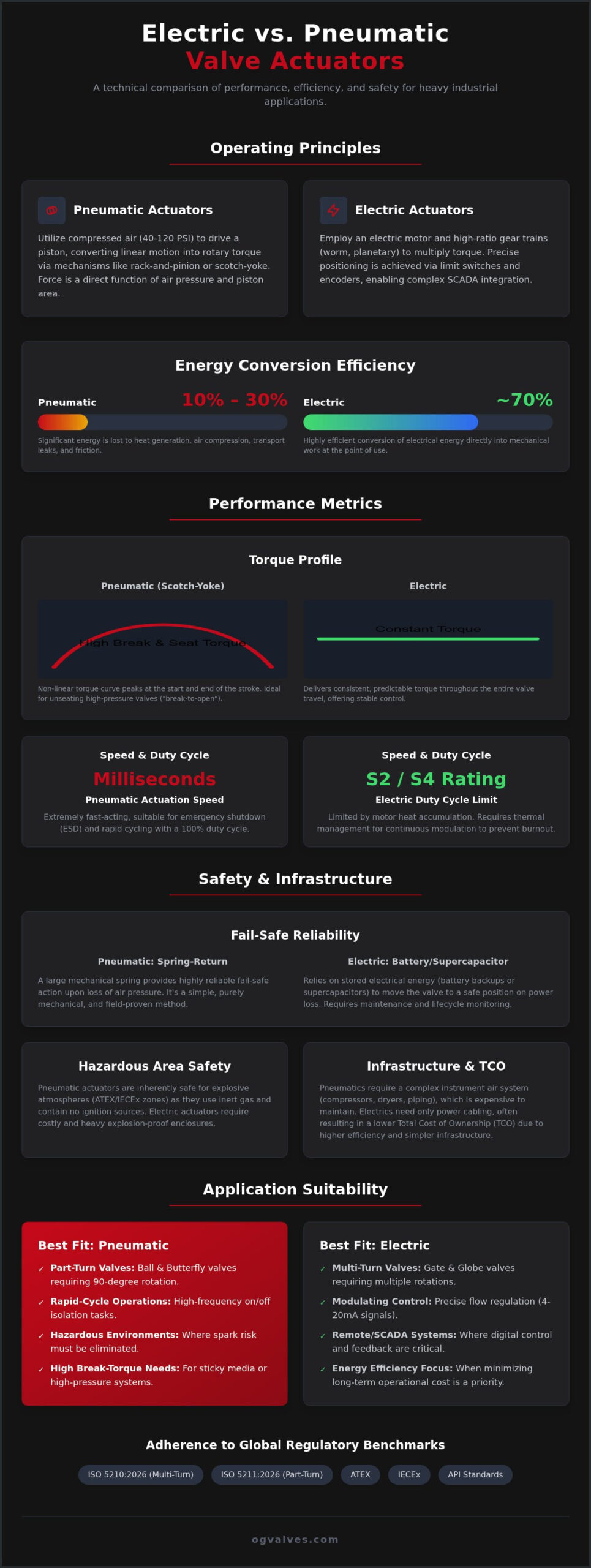
The decision to automate critical infrastructure often hinges on a single technical trade-off: the immediate high-torque response of compressed air versus the superior energy efficiency and precision of digital control. While pneumatic systems remain a staple in hazardous zones, many units convert as little as 10% to 30% of energy input into useful work. This efficiency gap is a primary driver in the ongoing debate of electric vs pneumatic valve actuators within heavy industrial sectors. You likely face the pressure of reducing infrastructure costs for instrument air while ensuring that fail-safe protocols meet the rigorous demands of API and ATEX standards.
This article provides a clinical technical analysis of both actuation methods to assist engineers in selecting the optimal automation for heavy industrial valve assemblies. We’ll examine the operational output of each system, focusing on the integration of ISO 5210:2026 and ISO 5211:2026 standards into modern SCADA frameworks. By evaluating torque profiles, duty cycles, and the total cost of ownership across the facility lifecycle, this comparison ensures your selection minimizes operational downtime and maintains compliance with global regulatory benchmarks.
Key Takeaways
- Identify the mechanical advantages of rack-and-pinion and scotch-yoke mechanisms compared to electromechanical gear trains for high-torque valve automation.
- Analyze divergent torque profiles and cycle speeds to determine the optimal drive system for rapid-response isolation versus continuous modulation.
- Evaluate fail-safe reliability by contrasting traditional mechanical spring-return systems with modern electric alternatives such as supercapacitors and battery backups.
- Apply a clinical framework to the electric vs pneumatic valve actuators debate by calculating the total cost of ownership (TCO) against infrastructure requirements.
- Ensure adherence to global regulatory benchmarks, including ATEX, IECEx, and API standards, through precise material selection and technical specification.
Operating Principles: Compressed Air vs. Electromechanical Drive
A Valve actuator serves as the primary mechanical interface between control logic and fluid flow. In the technical evaluation of electric vs pneumatic valve actuators, the primary distinction lies in how potential energy is converted into mechanical torque. Pneumatic units rely on fluid dynamics, utilizing compressed air to drive pistons, while electric variants employ electromagnetic induction to rotate complex gear trains. This fundamental difference dictates the unit’s suitability for specific valve geometries, such as multi-turn gate valves or part-turn butterfly and ball valves.
Pneumatic Force Generation
Pneumatic actuators typically utilize rack-and-pinion or scotch-yoke mechanisms to convert linear piston motion into rotary output. Instrument air pressure, generally regulated between 40 and 120 PSI, acts directly upon the piston surface area. Torque output is a direct function of piston diameter and stroke length. Rack-and-pinion designs provide consistent torque throughout a 90-degree rotation, making them suitable for standard ball valves. Scotch-yoke mechanisms are preferred for high-torque valves where a “break-to-open” force is required. Reliability depends on the integrity of dynamic seals and the consistent performance of lubricators within the pneumatic cylinder to prevent stiction and premature wear.
Electric Torque Transmission
Electric actuators utilize high-ratio gear assemblies, such as worm gears or planetary sets, to multiply the torque produced by compact motors. These units are compatible with various power supplies, including 110V/230V AC or 400V 3-phase systems for heavy-duty applications. Limit switches and encoders provide exact positioning, which is critical for modulating globe valves. Performance is governed by the duty cycle, typically classified under S2 (short-time) or S4 (intermittent) ratings. Continuous operation can lead to motor heat accumulation, necessitating thermal protection circuits that may halt operation to prevent winding failure. This precision makes them ideal for complex integration into SCADA frameworks.
Energy conversion efficiency represents a significant divergence in operating principles. Pneumatic systems are often inefficient; they’re known to lose significant energy through heat, friction, and transport leaks. Research indicates that only 10% to 30% of energy input reaches the valve stem in pneumatic setups. Electric systems are far more efficient, converting approximately 70% of electrical input into mechanical work. While pneumatic units excel in rapid-cycle part-turn applications like butterfly valves, electric actuators are the standard for multi-turn gate valves. Adherence to ISO 5210:2026 for multi-turn and ISO 5211:2026 for part-turn attachments ensures these drive systems integrate seamlessly with heavy industrial valve assemblies.
Torque delivery represents a critical performance differentiator in the electric vs pneumatic valve actuators selection process. Pneumatic scotch-yoke actuators generate a non-linear torque curve, peaking at the start and end of the stroke. This profile aligns with the “break-to-open” requirements of high-pressure ball valves. Conversely, electric actuators deliver constant torque throughout the entire travel range. While this provides predictable operation, it lacks the mechanical advantage inherent in pneumatic designs during the initial unseating of the valve disc or wedge.
Operating speed and duty cycles further define application suitability. Pneumatic units dominate rapid-cycle environments; they achieve full stroke in durations often measured in milliseconds without thermal degradation. Electric actuators are limited by motor duty cycles, typically S2 or S4 classifications under IEC 60034-1. Continuous modulation in electric units requires high-grade insulation and sophisticated thermal management to prevent motor burnout. In contrast, pneumatic systems operate effectively at a 100% duty cycle, provided the instrument air supply remains stable and dry.
Modulating Control and Precision
Precision in modulating flow control depends on the actuator’s ability to interpret 4-20mA or 0-10V control signals without signal degradation. Electric actuators offer superior repeatability and minimal deadband. They don’t suffer from the compressibility issues inherent in fluid power. Pneumatic systems often experience hysteresis, where the valve position varies based on the direction of travel. To achieve comparable accuracy, pneumatic assemblies require advanced digital positioners. These devices compensate for air compressibility, ensuring the assembly meets the requirements of high-stakes industrial processing.
Dynamic Response and Speed Control
Dynamic response management is essential to protect piping integrity and maintain structural soundness. Pneumatic speed is adjusted through flow control valves and exhaust mufflers. This allows for rapid opening but throttled closing. Modern electric actuators utilize variable speed drives to implement soft-start and soft-stop protocols. Electronic control is vital for managing water hammer risks in large-scale liquid transport. By precisely controlling the closing ramp, engineers prevent the pressure surges that lead to catastrophic pipe failure. Technical experts often consult with specialist suppliers to ensure the actuated valve assembly matches these specific hydraulic requirements.
Fail-Safe Mechanisms and Hazardous Area Safety
In high-stakes industrial environments, the selection between electric vs pneumatic valve actuators often depends on the required fail-safe response during a power or signal loss. Reliability in these scenarios is non-negotiable for Emergency Shutdown (ESD) valves. Pneumatic actuators utilize mechanical spring-return systems to provide a physical guarantee of valve positioning. This mechanism doesn’t rely on external power; the stored potential energy in the compressed spring forces the valve to its fail-open or fail-closed state the moment air pressure drops below the threshold. This simplicity makes pneumatic systems the preferred choice for applications requiring high Safety Integrity Level (SIL) ratings, particularly SIL 2 and SIL 3.
Spring-Return vs. Stored Energy
Electric actuators have historically struggled with fail-safe requirements, but modern technological advancements have bridged this gap. Engineers now specify electric units equipped with supercapacitors or integrated battery backup systems. Supercapacitors are favored for their rapid charging cycles and long operational life compared to traditional lead-acid batteries. While these systems allow for sophisticated SCADA integration, including “fail-last” or “fail-to-position” logic, they introduce additional complexity. Wiring requirements for battery-monitored units are more intensive, and the stored energy components must be regularly tested to ensure they maintain the necessary charge for emergency operations in corrosive environments.
Hazardous Area Protection
Compliance with ATEX and IECEx standards is mandatory for valve automation in explosive atmospheres. Pneumatic actuators are inherently explosion-proof because they don’t utilize electrical components within the drive unit. However, electric actuators must be housed in flameproof (Ex d) or intrinsically safe (Ex i) enclosures to prevent internal sparks from igniting the surrounding atmosphere. Enclosure ratings such as IP67 or IP68, along with NEMA 4X, provide the necessary protection against dust, water ingress, and salt-spray corrosion at outdoor industrial sites. A critical requirement for electric units is the inclusion of internal anti-condensation heaters. These heaters prevent moisture buildup within the housing, which is a common cause of electronic failure in high-humidity or fluctuating temperature zones.
Selecting between these systems ultimately balances the mechanical certainty of a spring against the data-rich feedback of an electronic fail-safe. While pneumatic springs offer unrivaled reliability in the simplest terms, electric fail-safes provide more granular control over the valve’s final position. Technical specialists must evaluate the specific risk profile of the facility to ensure that the chosen actuation assembly meets all local and international safety benchmarks without compromising operational output. This clinical approach to safety ensures that the infrastructure remains resilient under catastrophic failure conditions.
Infrastructure Requirements and Total Cost of Ownership
The selection process for electric vs pneumatic valve actuators must extend beyond the unit purchase price to account for total lifecycle costs. While pneumatic actuators often present a lower initial capital expenditure (CAPEX), the associated infrastructure for instrument air frequently exceeds the cost of the actuator itself. Research indicates that basic pneumatic units cost between $80 and $500, yet the total installation cost including compressors and piping can reach $1,000 to $5,000 per unit. Conversely, electric actuators carry a higher unit price, ranging from $300 to over $1,500, but they utilize existing electrical grids and reduce the need for specialized utility networks.
Pneumatic System Infrastructure
Pneumatic systems require a comprehensive support network including compressors, refrigerated dryers, and multi-stage filtration units to meet ISO 8573-1 air quality standards. Contaminants or moisture in the air line lead to premature seal failure and internal corrosion of the cylinder walls. In large-scale industrial facilities, managing pressure drops across extensive piping networks is a constant operational challenge. The energy efficiency of these systems remains low for 24/7 operations, as compressors must maintain line pressure regardless of valve activity, leading to high long-term operational expenditure (OPEX).
Electric System Integration
Electric system integration focuses on the complexity of power distribution and digital communication protocols. High-stakes industrial sites must manage extensive cable tray requirements for power, control, and feedback loops. Modern units integrate directly into Modbus, Profibus, or Foundation Fieldbus architectures, providing real-time diagnostic data that pneumatic systems lack without expensive digital positioners. However, signal integrity is a primary concern. Engineers must implement shielded cabling and proper grounding to mitigate electromagnetic interference (EMI) that can disrupt sensitive control logic in high-voltage environments.
Maintenance intervals differ significantly between the two technologies. Pneumatic units require periodic seal replacement and regular inspection of the air preparation system to prevent leaks. Electric actuators require less frequent mechanical intervention but necessitate specialized technical expertise for electronic component troubleshooting and gear train lubrication. For projects requiring specific material classifications and rigorous quality control, technical experts should consult with a specialist valve supplier to optimize the total cost of ownership across the facility lifecycle. This clinical assessment of infrastructure ensures that the chosen electric vs pneumatic valve actuators match the long-term performance requirements of the critical infrastructure.
Selection Framework: Matching Actuation to Valve Type
Selecting the correct drive system requires a clinical evaluation of the valve’s mechanical motion and the operational environment. High-performance butterfly valves in power generation often necessitate rapid modulation or immediate fail-safe closure. Pneumatic actuators are frequently the primary choice in these sectors due to their inherent speed and simple spring-return mechanics. In petrochemical isolation, ball valves require significant breakaway torque. The debate of electric vs pneumatic valve actuators in this context depends on existing facility infrastructure; pneumatic scotch-yoke units provide the necessary torque curve, while electric actuators offer superior precision for isolation monitoring. Multi-turn gate and globe valves present a different requirement, needing continuous rotation that exceeds the stroke limits of standard pneumatic cylinders. Refer to Industrial Valve Actuators: A Technical Guide to Automation and Control for detailed sizing.
Torque Safety Factors and ISO 5211
Precision in valve automation relies on rigorous torque safety factor calculations. For high-pressure applications, engineers must apply a safety factor of 1.25 to 1.5 to the valve’s breakaway torque. This margin accounts for increased friction caused by media buildup, high temperatures, or infrequent operation. Compatibility with ISO 5211:2026 mounting interfaces is mandatory to ensure structural alignment between the actuator and the valve stem. Misalignment leads to side-loading, which causes catastrophic seal failure and operational downtime. See The Engineer’s Guide to Industrial Butterfly Valves for mechanical details.
Procurement and Technical Support
Industrial procurement specialists should prioritize integrated valve-actuator assemblies to ensure guaranteed performance. Sourcing a pre-tested assembly eliminates the risk of component mismatch and ensures that the torque output remains sufficient across the entire travel range. OG VALVES LTD. acts as a dependable partner by providing technical support for complex industrial specifications, including material selection and PMI testing. The organization maintains an extensive inventory of API-compliant valves to support fast-track global delivery for critical infrastructure projects. This comprehensive project management approach ensures that every actuated unit meets the rigorous safety and performance benchmarks required in the oil, gas, and power generation sectors. You can request a technical quote for actuated valve assemblies to begin your facility’s automation review.
Optimising Automation Strategy for Critical Infrastructure
The final selection of electric vs pneumatic valve actuators requires a clinical assessment of operational requirements against infrastructure constraints. Pneumatic systems deliver high-torque output and mechanical fail-safe reliability for rapid-cycle applications; however, they impose high infrastructure costs for instrument air networks. Electric actuators provide the precision and energy efficiency necessary for complex SCADA integration but demand sophisticated thermal protection and electronic fail-safe alternatives. Engineers must balance these technical trade-offs to ensure long-term structural soundness and regulatory adherence across the facility lifecycle.
Achieving optimal performance in heavy industrial sectors involves an integrated approach to valve and actuator assembly that accounts for torque safety factors and material classifications. OG VALVES LTD. acts as an established global partner, offering specialist technical support for complex specifications and maintaining an extensive inventory of API-compliant valves. Our global delivery capabilities ensure that fast-track projects receive high-quality automation components without compromise. Consult with OG VALVES LTD. for high-specification actuated valve solutions to ensure your facility maintains the highest engineering standards and operational output.
Frequently Asked Questions
What is the primary advantage of pneumatic actuators over electric ones?
Pneumatic actuators provide high-speed operation and inherent safety in explosive atmospheres. These units achieve full stroke cycle times that electric motors can’t match without excessive wear. They’re capable of operating at a 100% duty cycle, whereas electric variants often require cooling periods. The choice of electric vs pneumatic valve actuators for rapid-cycle isolation depends on these thermal limits. Their mechanical simplicity ensures a lower unit cost for high-torque requirements.
Can electric actuators provide a true mechanical fail-safe?
Electric actuators don’t offer a true mechanical fail-safe in the traditional sense of a physical spring-return. Instead, they rely on stored energy systems like supercapacitors or integrated battery backups to drive the valve to a safe position during power loss. While these systems are highly reliable, they involve electronic components that require periodic testing. In contrast, pneumatic springs provide a physical guarantee of movement that doesn’t depend on any electrical charge.
Which actuator type is better for precise flow modulation?
Electric actuators are superior for precise flow modulation because they aren’t subject to the compressibility of air. They provide exact positioning with minimal deadband and hysteresis, which is critical for globe valve applications. When evaluating electric vs pneumatic valve actuators for proportional control, electric units offer better repeatability across 4-20mA signals. Pneumatic systems achieve similar accuracy only through the addition of high-specification digital positioners that compensate for fluid dynamic fluctuations.
How does duty cycle affect electric valve actuator selection?
Duty cycle ratings, such as S2 or S4, define the operational limits of an electric motor before heat accumulation causes failure. Selecting an electric unit with an insufficient rating for a high-frequency modulating application leads to premature motor burnout. Pneumatic actuators aren’t limited by duty cycles; they’re able to cycle continuously as long as the instrument air supply is maintained. Engineers must verify the frequency of operation to ensure the actuator’s thermal management matches the facility’s output.
What are the infrastructure requirements for a pneumatic actuator system?
A pneumatic system requires a robust utility network consisting of industrial compressors, refrigerated air dryers, and multi-stage filtration units. The air must meet ISO 8573-1 standards to prevent moisture or particulate matter from damaging internal seals. Additionally, a complex network of stainless steel or copper piping is necessary to deliver consistent pressure to the valve assembly. These infrastructure components represent a significant portion of the total cost of ownership for any pneumatic installation.
Are electric actuators suitable for hazardous (ATEX) environments?
Electric actuators are suitable for ATEX and IECEx environments if they’re specified with flameproof or intrinsically safe enclosures. These specialized housings prevent any internal electrical spark from igniting the surrounding hazardous atmosphere. While pneumatic units are inherently safe due to the absence of electricity, modern electric actuators meet the same rigorous safety benchmarks. Proper cable glands and anti-condensation heaters are mandatory to maintain the integrity of these enclosures in volatile oil and gas sectors.
How do I determine the torque requirement for an actuated butterfly valve?
Torque requirements for an actuated butterfly valve are determined by summing the unseating torque, dynamic fluid torque, and a mandatory safety factor. Technical experts typically apply a safety factor between 1.25 and 1.5 to the manufacturer’s breakaway torque rating. This calculation must account for the specific gravity and viscosity of the media, as well as the potential for seat degradation over time. Ensuring compatibility with ISO 5211 mounting interfaces is the final step in securing a sound assembly.
What is the typical lifespan of an industrial valve actuator?
The lifespan of an industrial valve actuator varies based on the operating environment and maintenance frequency, but high-quality units often exceed 15 to 20 years of service. Pneumatic actuators require periodic seal replacements to maintain pressure integrity, while electric units depend on the durability of their gear trains and electronic control boards. Factors like salt-spray corrosion and extreme temperature fluctuations directly impact longevity. Regular testing and adherence to manufacturer lubrication schedules are essential for preventing catastrophic failure.
 Responsive Menu