How to Prevent Steam Valve Failure: A Technical Guide to Industrial System Integrity
March 21, 2026
Home+How to Prevent Steam Valve Failure: A Technical Guide to Industrial System Integrity
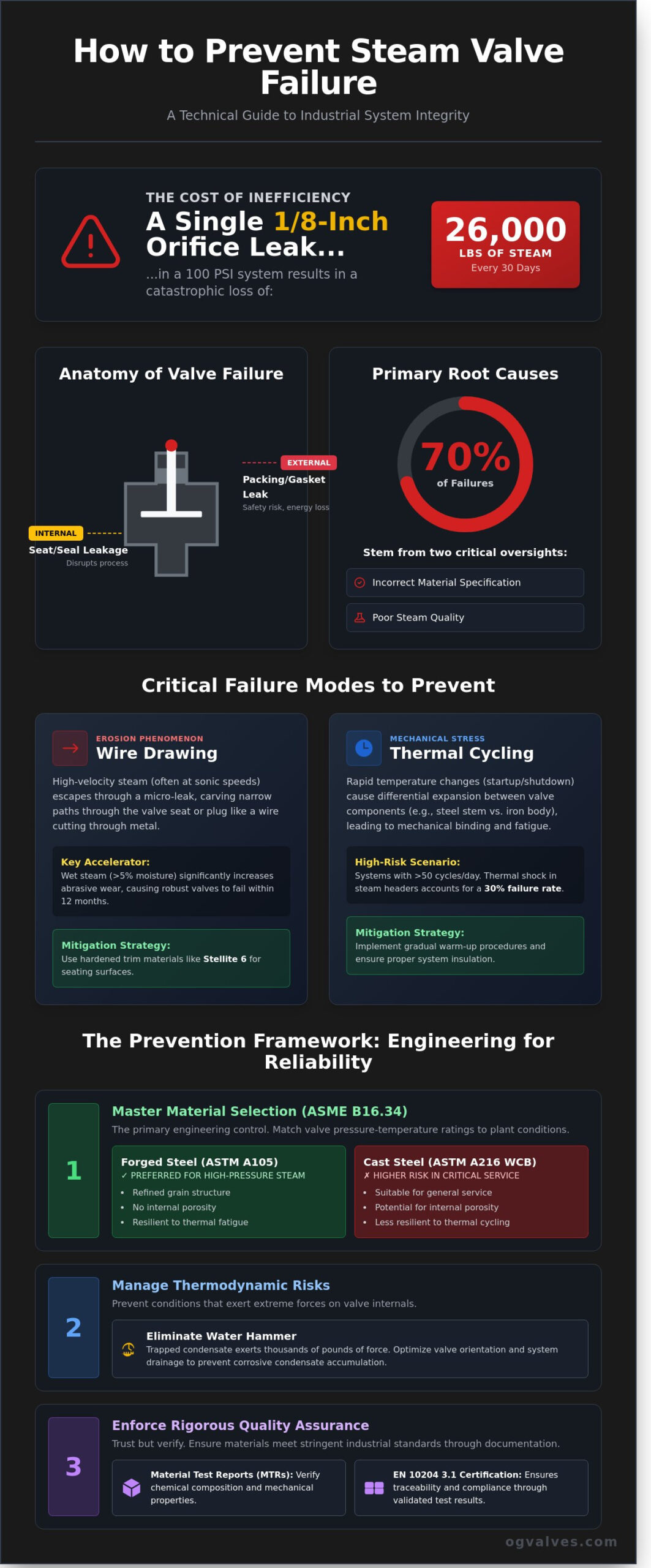
A single 1/8-inch orifice leak in a 100 PSI steam system results in the loss of approximately 26,000 pounds of steam every 30 days. This technical inefficiency translates to thousands of dollars in wasted energy before a technician even identifies the source of the thermal degradation. Senior engineers recognize that unplanned downtime caused by component fatigue remains the primary driver of escalated OPEX and catastrophic safety risks. Mastering how to prevent steam valve failure isn’t just a maintenance goal; it’s a fundamental requirement for maintaining industrial system integrity and adhering to ASME B16.34 standards.
You’ll gain the engineering principles and proactive strategies required to eliminate premature component failure while ensuring long-term plant reliability. This technical guide provides a clinical analysis of material performance, pressure-temperature ratings, and the specific diagnostic protocols needed to extend valve service life. We’ll examine critical failure modes like wire drawing and thermal fatigue to establish a framework for rigorous industrial compliance and safety across your infrastructure.
Key Takeaways
Identify the fundamental mechanics of pressure containment loss and distinguish between internal seat leakage and external packing failure to maintain system control.
Apply ASME B16.34 standards to select appropriate material grades, such as forged A105 or cast WCB, specifically for high-pressure steam header service.
Learn how to prevent steam valve failure during the critical commissioning phase by implementing industrial flushing protocols and debris removal strategies.
Calculate thermodynamic risks to eliminate water hammer and optimize valve orientation to prevent the accumulation of corrosive condensate.
Secure long-term reliability by verifying Material Test Reports (MTRs) and EN 10204 3.1 certification through rigorous procurement and quality assurance processes.
The Mechanics of Steam Valve Failure: Identifying Root Causes
Steam valve failure is defined as a loss of pressure containment or a failure in functional control. In high-stakes industrial environments, this failure presents as either internal or external leakage. Internal leakage occurs when the seat or seal degrades; this allows steam to bypass the closure member and disrupts process parameters. External leakage occurs at the packing or the body-bonnet gasket, creating immediate safety risks and energy losses. Understanding these specific failure points is essential for plant engineers learning how to prevent steam valve failure in high-pressure steam loops.
The unique stresses of steam service include high temperatures, extreme pressures, and high fluid velocities. Typical industrial systems maintain temperatures exceeding 280°C and pressures above 40 bar. These conditions subject valve internals to relentless mechanical stress. Condensate and non-condensable gases like oxygen or carbon dioxide introduce additional variables. When condensate is trapped in the line, it causes water hammer, which exerts thousands of pounds of force on valve internals. A failure in the safety chain, such as a seized relief valve, can lead to a catastrophic Boiler explosion, emphasizing the need for rigorous maintenance. Identifying these root causes is the primary step in determining how to prevent steam valve failure across the infrastructure.
Technical data from industrial audits indicates that 70% of steam valve failures stem from incorrect material specification or poor steam quality. Engineers must ensure compliance with ASME B16.34 standards to match the valve’s pressure-temperature rating with the application’s requirements. Since the 2021 update to these standards, there’s a clinical focus on material integrity. Neglecting these specifications results in premature component fatigue and increased operational risk.
Erosion and Wire-Drawing in Steam Service
Wire-drawing is a specialized erosion phenomenon where high-velocity steam carves narrow paths through the valve seat or plug. It starts with a microscopic leak. As steam escapes through this gap, its velocity increases, often reaching sonic speeds. This high-speed flow cuts into the metal like a wire, destroying the seating surface. Wet steam, containing more than 5% moisture, significantly accelerates this abrasive wear. Using hardened materials like Stellite 6 for trim components is a standard industry practice to mitigate this damage. If operators don’t maintain steam quality, even the most robust valves will fail within 12 months of service.
Thermal Cycling and Mechanical Stress
Thermal cycling occurs when a valve undergoes rapid temperature changes during system start-up or shut-down. This causes differential expansion between the valve stem, seat, and body. For instance, a 316 stainless steel stem expands at a different rate than a cast iron body. This mismatch creates mechanical binding or galling, where the stem becomes stuck. High-frequency cycling applications, defined as those exceeding 50 cycles per day, are particularly prone to fatigue failure. These systems require specialized packing configurations that meet ISO 15848-1 fugitive emission standards. Proper insulation and gradual warm-up procedures help reduce the 30% failure rate associated with thermal shock in steam headers.
Material Specification: Selecting Valves for High-Temperature Steam
Selecting the correct material is the primary engineering control for how to prevent steam valve failure. Compliance with ASME B16.34 is the baseline requirement. This standard defines the pressure-temperature ratings that dictate the safe operating limits of the valve body. Engineers must ensure the valve material matches the specific steam saturation curve or superheat conditions of the plant. For steam headers, forged steel (ASTM A105) offers significant advantages over cast steel (ASTM A216 WCB). The forging process eliminates internal porosity and creates a refined grain structure. This makes A105 more resilient to the thermal fatigue common in high-pressure steam distribution. While WCB is suitable for general service, the 0.30% maximum carbon content in forged steel provides better weldability and structural integrity for critical infrastructure.
Hard-facing is essential for protecting internal components from the high-velocity erosion known as wire-drawing. When steam passes through a partially open valve, it can cut through standard stainless steel seats in a matter of hours. Specifying Stellite™ (Cobalt-Chrome alloy) on the seat rings and disc surfaces provides a hardness level typically exceeding 37 HRC. This protective layer maintains the seal integrity even when subjected to the abrasive effects of wet steam or particulate matter. API 600 serves as the rigorous benchmark for steam gate valves. This standard mandates heavier wall thicknesses and larger stem diameters than general-purpose valves. Adhering to OSHA steam system standards ensures that these material choices meet federal safety requirements for high-pressure energy isolation.
Metallurgy and Corrosion Resistance
Carbon steel faces a high risk of graphitisation when exposed to temperatures above 425°C for extended periods. In this process, the carbon in the steel precipitates into graphite nodules, which embrittles the metal and leads to sudden fracture. To mitigate this, superheated steam systems require Chrome-Moly alloys such as ASTM A182 F11 or F22. The chromium content (1.25% to 2.25%) stabilizes the carbides and increases creep strength. Additionally, the chemistry of boiler water treatment, including the use of oxygen scavengers like hydrazine, can impact valve life. These chemicals maintain the protective magnetite layer on the valve internals, but incorrect dosing can lead to flow-accelerated corrosion in lesser-grade alloys.
Sealing Technology: Packing and Gaskets
Sealing integrity is a critical factor in how to prevent steam valve failure and fugitive emissions. Graphite-based packing is the industry standard for high-temperature steam because it remains thermally stable up to 650°C. For flange connections, spiral wound gaskets with 316 stainless steel windings and flexible graphite fillers are required to handle the constant thermal cycling. In ultra-high-pressure services exceeding 1500# class, pressure-seal bonnet designs are the preferred choice. These designs utilize the internal system pressure to compress a soft metal or graphite gasket, creating a tighter seal as the pressure increases. Consulting with an expert on industrial valve specifications ensures that these sealing technologies are correctly matched to the system’s operational pressure and temperature profiles.
Mitigating Acute Failure During System Commissioning
Acute valve failure during the initial 72 hours of system operation is a frequent occurrence in new steam installations. This “start-up failure” syndrome is rarely a result of manufacturing defects. Instead, it’s typically caused by the introduction of foreign particulates into the valve internals during the transition from construction to operation. Data from industrial field audits suggest that up to 15% of control valve trim damage occurs during the first 100 hours of service. When engineers evaluate how to prevent steam valve failure, they must prioritize the elimination of construction debris that accumulates during the fabrication of carbon steel piping networks. Implementing these protocols is the most effective method for how to prevent steam valve failure in high-pressure environments.
Welding slag, metal shavings, and heavy pipe scale act as high-velocity projectiles within the steam flow. A single 2mm bead of welding splatter can impact a valve seat with enough force to create deep scoring. This mechanical damage compromises the metal-to-metal seal, leading to immediate internal leakage that fails ISO 5208 leakage standards. Once the seat profile is altered, the high-pressure steam creates a wire-drawing effect that rapidly erodes the remaining material. This erosion is particularly aggressive in ASTM A105 forged steel bodies where the velocity of the steam can exceed 45 meters per second. Maintaining system integrity requires a clinical focus on cleanliness before the first isolation valve is cycled. Proper adherence to preventing steam leaks involves a rigorous approach to removing these abrasive elements before they reach sensitive instrumentation.
Pre-Commissioning Flushing Protocols
The execution of a formal steam-blow procedure is mandatory for clearing carbon steel piping of mill scale and magnetite. This process involves high-velocity steam discharge through temporary bypass piping to ensure the kinetic energy of the steam dislodges internal contaminants. Contractors should install 40-mesh temporary strainers upstream of all critical valves for the initial 100-hour run-in period. Technicians must verify valve bore cleanliness and internal seat condition before the final torqueing of flange bolts. This protocol ensures that the valve enters service in a state of peak mechanical readiness, adhering to ASME B31.1 power piping standards and preventing premature seat degradation.
The Role of Steam Filters and Separators
High-quality steam must be dry and free of suspended solids to protect precision-machined valve components. Steam separators with a 99% efficiency rating should be positioned at the header and before every major branch to remove entrained condensate. For sensitive control valve trim, such as 316L stainless steel cage-guided plugs, fine mesh filtration is required to capture sub-micron particulates. Engineers must specify the correct orientation for Y-strainers in horizontal lines. Installing the strainer basket in the horizontal plane, rather than the vertical plane, prevents the formation of “dirt pockets” and potential water hammers. This configuration is essential for maintaining the long-term performance and compliance of the entire steam distribution network.
Thermodynamic stability is the primary defense against systemic component degradation in industrial steam systems. Engineers must prioritize the rigorous calculation of kinetic energy within steam lines to understand how to prevent steam valve failure across high-pressure networks. When steam velocity exceeds 35 meters per second, entrained condensate creates a “slug flow” scenario. This physical phenomenon delivers impact forces that often exceed 60 times the rated operating pressure, leading to immediate structural compromise of the internal trim.
Water Hammer Mitigation Strategies
Slug flow occurs when high-velocity steam travels over accumulated condensate, lifting the liquid and accelerating it into downstream hardware. This impact often shatters check valve discs or causes permanent seat misalignment. To counter this, specify non-slam check valves featuring spring-assisted closures that activate in under 0.4 seconds. Maintaining insulation integrity is equally vital. High-quality mineral wool or calcium silicate insulation reduces thermal loss by 85% to 92%, effectively keeping the steam above its saturation point and preventing the liquid phase change that initiates hammer events.
Valve orientation is a strict technical requirement rather than a field preference. Installing a globe valve with its stem in the downward vertical position creates a stagnant condensate pocket. This encourages localized galvanic corrosion and subjects the stem packing to unnecessary thermal shock during startup cycles. Upstream of any critical isolation point, implement a monthly steam trap audit. Data from industrial surveys suggests that 15% to 25% of steam traps fail within three years of installation. A failed trap leads directly to condensate accumulation and subsequent valve erosion. It’s a failure point that’s often overlooked during routine inspections.
Pressure equalization is another critical factor in long-term durability. Utilizing slow-opening bypass valves allows for a controlled thermal soak of the downstream piping. This prevents the 140% pressure spikes that occur when a main header valve is opened against a cold, unpressurized line. For components operating at temperatures exceeding 450°C, engineers must account for “creep.” This is the time-dependent deformation of metal under stress. After 10,000 to 15,000 hours of continuous service, even forged steel components require inspection for dimensional changes that could compromise the pressure boundary. Don’t assume that visual integrity equates to structural safety after these thresholds.
Predictive Maintenance and Monitoring
Ultrasound testing provides a non-invasive method to detect internal through-seat leakage by isolating the high-frequency acoustic signature of turbulent flow. Thermal imaging identifies packing failure by mapping heat signatures across the valve bonnet. During scheduled turnarounds, Positive Material Identification (PMI) is a mandatory protocol. This process verifies that every component meets the specific alloy requirements defined in ASME B16.34, ensuring that sub-grade materials don’t compromise the integrity of the steam system. This clinical approach to monitoring ensures that maintenance is based on data rather than speculation.
Industrial Procurement: Ensuring Quality and Compliance
Industrial procurement serves as the primary technical barrier against system degradation. Understanding how to prevent steam valve failure begins at the point of specification. It’s a process that requires working with specialist suppliers who possess a deep technical grasp of steam’s unique thermodynamic properties. Generalist vendors often overlook the nuances of thermal expansion and condensate erosion, which leads to premature component fatigue. A specialist partner provides the engineering depth needed to select valves that withstand the rigors of high-pressure service.
Verifying Material Test Reports (MTRs) and EN 10204 3.1 certification is mandatory for all pressure-retaining components. These documents provide 100% traceability to the original melt shop, ensuring the chemical composition of the steel meets ASTM A105 or A182 standards. In a 2023 industry survey, 12% of steam system failures were traced back to non-compliant alloy compositions that failed to withstand high-temperature service. This procurement strategy is the most effective way how to prevent steam valve failure in high-cycle environments.
OG VALVES LTD. ensures technical integrity through a rigorous testing protocol that exceeds basic ISO 9001:2015 requirements. Every unit is subjected to hydrostatic and pneumatic seat leakage tests according to API 598. We also perform 100% visual and dimensional inspections to confirm that wall thicknesses meet ASME B16.34 specifications. This clinical focus on precision eliminates latent manufacturing defects before the valve reaches the field, providing a benchmark for industrial safety.
Planning for fast-track delivery is a necessity for preventing extended downtime. A single day of steam system failure can cost an industrial facility $45,000 in lost energy and production. We maintain a robust supply chain that allows for the rapid dispatch of forged and cast steel valves. This proactive approach ensures that critical infrastructure remains operational without the delays associated with standard 16-week lead times. Reliability in procurement translates directly to reliability in the plant.
Standardisation and Inventory Management
Standardizing valve types across a facility simplifies the maintenance cycle. It reduces the volume of unique spare parts held in stock by 22% and streamlines the training required for repair technicians. Using a consistent set of specifications for gate and globe valves ensures that replacement components are always compatible with existing pipework. See our guide to Industrial Gate Valves for more on optimizing your inventory.
Global Supply and Technical Support
Leveraging global logistics allows for the rapid acquisition of specialized materials like F22 or F91 chrome-moly steel. Our engineering team provides technical support for difficult material specifications to ensure compliance with high-pressure steam standards. This global reach, combined with deep technical expertise, makes us a dependable partner for critical infrastructure projects. Request a technical quote for your steam valve requirements to ensure your system meets all safety protocols.
Securing Long-Term Steam System Integrity
Maintaining industrial system integrity requires a multi-layered approach to material selection and thermodynamic control. Engineers must prioritize valves that meet ASME B16.34 standards to ensure pressure-temperature ratings align with operational demands. Understanding how to prevent steam valve failure involves more than routine maintenance; it necessitates the integration of high-grade components like forged F22 or F91 steel that withstand 1,100°F temperatures without creep deformation. Proper commissioning protocols, including the elimination of condensate to prevent 100-G force water hammer impacts, remain critical for operational safety. OG Valves operates as a specialist supplier to the Oil, Gas, and Power sectors, providing components that undergo 100% hydrostatic testing before dispatch. Our global fast-track delivery infrastructure is designed to fulfill critical orders within 72 hours, minimizing downtime in high-stakes environments. We maintain rigorous adherence to API 6D and ISO 9001:2015 protocols to eliminate technical ambiguity during the procurement process. Request a Technical Specification Quote from OG Valves to secure your infrastructure against preventable mechanical decline. We’re ready to support your next high-pressure project with precision engineering.
Frequently Asked Questions
What is the most common cause of steam valve failure?
Erosion caused by condensate or particulate matter accounts for approximately 75% of steam valve failures in industrial systems. Scale buildup from untreated boiler water restricts travel and prevents a tight seal. To understand how to prevent steam valve failure, engineers must implement a rigorous water treatment protocol that maintains total dissolved solids below 2,500 ppm. This proactive approach ensures seat integrity and extends the component’s operational lifecycle.
How can I tell if my steam valve is leaking internally?
Internal leakage is typically identified through a temperature differential of 10 to 15 degrees Celsius between the upstream and downstream sides of a closed valve. Maintenance teams use ultrasonic leak detectors to capture high-frequency sounds generated by turbulent flow through a compromised seat. According to ISO 15848-1 standards, even minor fugitive emissions indicate a failure in the sealing mechanism. Regular thermal imaging scans help identify these thermal signatures before they cause system-wide pressure drops.
Why is water hammer so dangerous for steam valves?
Water hammer is dangerous because it generates pressure surges up to 50 times the normal operating pressure of the steam line. These shockwaves travel at 1,400 meters per second; they cause catastrophic fatigue to valve bodies and internal trim. Following ASME B31.1 piping codes reduces this risk by ensuring proper condensate drainage. If slugs of water strike a closed valve disc, the kinetic energy often results in cracked castings or sheared stems.
What material is best for high-pressure steam valves?
ASTM A182 F22 or F91 chrome-moly steel is the superior material for high-pressure steam service exceeding 540 degrees Celsius. These alloys provide high creep resistance and tensile strength under extreme thermal stress. Forged steel variants are preferred over cast options for their refined grain structure and lack of internal porosities. Proper material selection is a critical component of how to prevent steam valve failure in supercritical power plants.
How often should steam valves be inspected in a power plant?
Steam valves in power generation facilities require a comprehensive physical inspection every 12 to 24 months during scheduled outages. API 570 guidelines mandate that high-pressure components undergo non-destructive testing, such as dye penetrant or radiographic exams, at these intervals. Continuous monitoring of packing glands and actuators should occur weekly. This frequency ensures that minor wear doesn’t escalate into a forced shutdown, maintaining 99.9% plant availability.
Can I use a standard gate valve for throttling steam?
You shouldn’t use a standard gate valve for throttling because it’s designed exclusively for fully open or fully closed service. Operating a gate valve at a 10% or 20% open position causes severe turbulence and vibration. This leads to a 30% increase in mechanical wear on the disc and seat faces. For flow regulation, engineers must specify a globe valve or a specialized control valve that can withstand the high-velocity steam flow.
What is ‘wire-drawing’ in steam valves and how do I stop it?
Wire-drawing is the erosion of a valve seat caused by high-velocity steam leaking through a small opening, creating deep grooves that look like drawn wire. You can stop this by using hardened trim materials like 400 series stainless steel with a Rockwell C hardness of at least 45. Ensuring the valve closes with sufficient torque prevents the initial leak. If a valve isn’t bubble-tight, the steam’s kinetic energy will destroy the seating surface within 48 hours.
Should I choose forged or cast steel for steam service?
Choose forged steel, such as ASTM A105, for high-pressure steam lines with diameters under 2 inches due to its superior structural integrity. Forging eliminates internal voids and gas pockets that often occur in the casting process. For larger applications exceeding 2 inches, cast steel like ASTM A216 WCB is the industry standard for its cost-effectiveness and complex shape capabilities. Both materials must meet rigorous ASME Section II specifications to ensure safety in steam environments.
 Responsive Menu