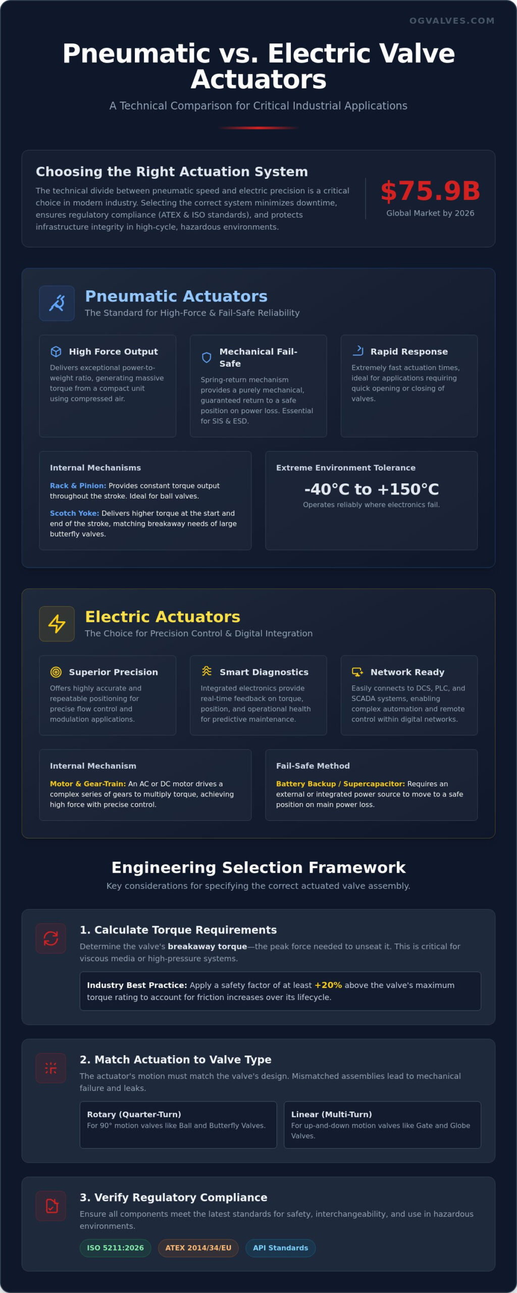
With the global valves and actuators market reaching USD 75.9 billion in 2026, the technical divide between pneumatic vs electric valve actuators has narrowed to a critical choice between mechanical failsafe speed and digital edge-computing precision. You recognize that unplanned downtime and the complexities of ATEX 2014/34/EU compliance represent significant operational risks in heavy industrial sectors. Selecting the wrong actuation system for a high-cycle gate or butterfly valve doesn’t just increase maintenance overhead. It compromises the structural integrity of your entire automated infrastructure.
This guide provides a comprehensive engineering framework to evaluate these systems against the latest ISO 5211:2026 standards and API requirements. We’ll analyze torque characteristics, duty cycles, and the integration of smart diagnostics to ensure your selection optimizes long-term valve performance in hazardous environments. By contrasting the rapid action of pneumatic systems with the precise connectivity of modern electric units, we offer a technical roadmap for reducing failure rates and ensuring regulatory adherence across global supply chains.
Key Takeaways
- Establish a clear technical framework for evaluating pneumatic vs electric valve actuators based on lifecycle costs and infrastructure constraints.
- Identify why pneumatic systems remain the industry standard for high-force applications and critical fail-safe reliability in explosive environments.
- Evaluate the integration of electric actuators for precise flow regulation and real-time diagnostic feedback within automated digital networks.
- Verify adherence to updated ISO 5211:2026 and ATEX standards to ensure regulatory compliance and operational safety.
- Learn the technical specifications required for sourcing high-performance actuated ball, butterfly, and gate valve assemblies for corrosive service.
Core Functional Differences in Industrial Valve Actuation
Valve actuation is the automation of mechanical flow control, replacing manual operation with precise and repeatable positioning. This Valve actuator overview highlights how these units convert energy into the mechanical force needed to manipulate a valve’s closure member. In heavy industrial applications, the technical decision between pneumatic vs electric valve actuators usually depends on the available infrastructure and the specific torque requirements of the piping system.
The mechanical architecture differs significantly between the two types. Pneumatic actuators use compressed air to drive a piston or diaphragm against a spring or air return. This design is valued for its simplicity and high power-to-weight ratio. Electric actuators use AC or DC motors combined with complex gear-trains to achieve high-torque output. While pneumatic units offer rapid response times, electric units provide superior positioning accuracy. Both systems must adhere to the latest ISO 5211:2026 standards for mounting interfaces. This standard ensures that bolt patterns and drive couplings are compatible with the valve stem, which prevents misalignment and reduces mechanical wear on the packing seals.
Rotary vs Linear Actuation Requirements
The kinematic requirements of the valve dictate the actuator’s basic architecture. Ball valves and butterfly valves utilize quarter-turn motion, requiring a rotary actuator that rotates exactly 90 degrees. In contrast, gate valves and globe valves require linear or multi-turn motion to move the stem up or down. You can’t simply swap these designs; the internal gearing or piston stroke must match the valve’s travel distance. Sourcing a pre-tested assembly ensures that the actuator’s travel limits are factory-set to prevent over-torquing the valve seats.
The Importance of Torque and Thrust Specifications
Determining the correct output force is essential for operational reliability. Breakaway torque is the peak force needed to unseat a valve after it’s been closed for an extended period. This requirement often spikes when the media is viscous or contains abrasive particulates. It’s standard engineering practice to apply a safety factor of at least 20% above the valve manufacturer’s maximum torque rating. This buffer accounts for potential increases in friction over the valve’s lifecycle. Precision in these calculations prevents motor burnout in electric units and ensures that pneumatic systems have enough air pressure to overcome high-pressure differentials.
Pneumatic actuators remain the primary specification for heavy industrial applications requiring rapid response and high torque output. According to 2025 market data, pneumatic models accounted for 37.63% of total revenue. This dominance stems from their inherent mechanical simplicity. When comparing pneumatic vs electric valve actuators, the power-to-weight ratio of a compressed air system is significantly higher. A compact pneumatic unit can generate the same thrust as a much larger electric equivalent. This makes them ideal for space-constrained piping skids in the petrochemical sector.
The choice of internal mechanism depends on the valve’s torque curve. Rack and pinion designs provide a constant torque output throughout the 90-degree stroke, which is suitable for standard ball valves. Scotch yoke mechanisms offer higher torque at the beginning and end of the stroke. This matches the breakaway torque requirements of large-bore butterfly or plug valves. These mechanical systems operate effectively in extreme temperatures ranging from -40°C to over 150°C, where electronic components often fail.
Mechanical Fail-Safe Mechanisms
Safety Instrumented Systems (SIS) rely on the mechanical reliability of pneumatic spring-return actuators. In a single-acting configuration, a heavy-duty spring provides the energy to move the valve to a predetermined safe position upon loss of air pressure. This is a critical distinction in the pneumatic vs electric valve actuators debate. While electric units require complex battery backups or supercapacitors to achieve fail-safe status, pneumatic springs provide a purely mechanical guarantee. For critical emergency shut-down (ESD) services, the addition of local air reservoir tanks ensures multiple cycles are possible even if the main plant air supply is compromised.
Maintenance and Air Quality Standards
Long-term reliability depends on the quality of the motive fluid. Compliance with ISO 8573-1 is mandatory to prevent internal component degradation. Compressed air must be dry and filtered to remove particulates and oil aerosols that cause seal swelling or solenoid sticking. While pneumatic cylinders are designed for millions of cycles, seal kits require periodic replacement every 3 to 5 years depending on the duty cycle. Implementing a rigorous preventative maintenance schedule reduces the risk of unplanned downtime in high-stakes environments like offshore platforms or power generation facilities.
Electric Actuators: Precision Control and Integrated Digital Feedback
Electric actuators facilitate the transition toward digital precision in industrial flow control. While previous sections analyzed the mechanical force of compressed air, electric units utilize AC or DC motors coupled with high-ratio gear reduction. This architecture is essential for modulating services where exact valve positioning is required. In the pneumatic vs electric valve actuators comparison, electric units provide superior accuracy by eliminating the positioning drift caused by air compressibility. Market projections indicate that electric actuators will account for 48% of the global market share by 2036, reflecting a shift toward electrified infrastructure.
Modern smart actuators function as integrated sensing and edge-computing terminals. These units feature embedded diagnostics that monitor torque profiles, motor temperature, and cycle counts in real-time. This data is transmitted through digital BUS communication protocols such as PROFIBUS or Foundation Fieldbus. This level of connectivity enables predictive maintenance strategies, which are critical for reducing the high cost of unplanned downtime in heavy industrial sectors. It allows operators to identify potential valve sticking or seat wear before a total component failure occurs.
Operational energy efficiency is another primary driver for electrification. Electric units consume power only during the actuation cycle. In contrast, pneumatic systems require the continuous operation of compressor plants and are subject to energy losses through air line leakage. For facility retrofits, the simplicity of electrical cabling often provides a more cost-effective automation solution than the installation of new piping and filtration systems required for pneumatic motive force.
Duty Cycle and Thermal Management
Motor heat is the primary performance constraint for electric actuation. Duty cycle ratings, categorized from S1 for continuous operation to S4 for intermittent service, define the operational limits of the motor. High-frequency modulating tasks can lead to thermal accumulation. Most industrial units incorporate thermal overload protection to prevent winding damage. This represents a significant operational difference in the pneumatic vs electric valve actuators evaluation, as pneumatic cylinders naturally dissipate heat through exhaust air and don’t suffer from thermal lockout during high-cycle service.
Hazardous Area Compliance
Deploying electrical components in explosive environments requires rigorous adherence to international safety standards. The 6th Edition of the ATEX 2014/34/EU Guidelines, released in January 2026, now permits digital documentation via QR codes on product labels for the EU Declaration of Conformity. Enclosures must be explosion-proof and rated with IP67 or IP68 ingress protection for submersible or outdoor petrochemical service. Achieving fail-safe performance is more complex for electric units than the mechanical spring-return systems used in pneumatics. It requires integrated battery backups or supercapacitors that provide sufficient stored energy to drive the motor to a safe position during a power failure.
Engineering Selection Matrix: Environmental and Operational Constraints
The decision-making process for specifying pneumatic vs electric valve actuators necessitates a multi-variable analysis of environmental limits and lifecycle costs. While previous sections detailed the mechanical and digital capabilities of each system, the selection matrix must account for the supporting infrastructure. Pneumatic systems require a centralized compressor plant, high-capacity dryers, and an extensive network of stainless steel or copper tubing. Electric systems rely on existing power grids or localized solar and battery setups. This infrastructure requirement often dictates the initial capital expenditure (CAPEX) for new facilities or major retrofits.
Environmental extremes further complicate the selection. In sub-zero temperatures, pneumatic systems face high risks of line freezing if the air supply isn’t perfectly dried to a low pressure dew point. Electric actuators don’t suffer from line freezing but require internal space heaters to prevent condensation and maintain the viscosity of gear lubricants. Regarding operational precision, electric systems provide superior repeatability with hysteresis levels often below 0.5% in modulating service. Pneumatic systems can struggle with “hunting” in control loops due to the inherent compressibility of air, particularly in long-run piping where signal lag is more pronounced.
Total Cost of Ownership (TCO) Analysis
Air leaks represent a significant, often invisible, drain on facility efficiency. Industry reports suggest that poorly maintained compressed air systems can lose up to 30% of their volume through undetected leaks in manifolds and fittings. This elevates the long-term OPEX of pneumatic systems. Conversely, electric actuators have a higher unit-level CAPEX but consume energy only during movement. In corrosive petrochemical environments, the lifespan of both systems depends on enclosure materials. Sourcing units with high-specification coatings or stainless steel housings is essential for preventing structural degradation over a 10 to 15-year service life.
Application-Specific Recommendations
Selecting the optimal actuation technology depends on the primary operational objective of the installation:
- Remote Pipelines: Solar-powered electric actuators are preferred where plant air is unavailable, as they eliminate the need for gas-over-oil systems that can vent greenhouse gases.
- Refinery Safety Systems: Pneumatic spring-return units remain the standard for Safety Instrumented Systems (SIS) due to their purely mechanical fail-safe guarantee.
- Precise Chemical Dosing: Modulating electric actuators are required for actuated valve assemblies in dosing loops where fine-step resolution and digital feedback are critical for process stability.
Consult with our technical team to receive a detailed specification for your high-pressure piping projects to ensure compliance with the latest efficiency and safety benchmarks.
Procurement and Integration: Specifying Actuated Valve Assemblies
Sourcing pre-assembled and tested valve-actuator packages is a standard industry practice to reduce integration risks at the job site. This approach ensures that the mounting interface, including brackets and couplings, meets the precision tolerances required by the latest ISO 5211:2026 standards. It eliminates the common problem of mismatched stem adapters that lead to premature seal failure or stem side-loading. Every assembly undergoes a Factory Acceptance Test (FAT) to verify that the torque output of the pneumatic vs electric valve actuators matches the valve’s operational requirements under full differential pressure.
Material compatibility remains a critical specification point. The actuator drive must be compatible with the valve stem material to prevent galvanic corrosion or mechanical galling. For projects in corrosive petrochemical environments, specifying stainless steel hardware or specialized epoxy coatings is necessary for long-term structural soundness. Procurement specialists must demand comprehensive regulatory documentation. This includes Material Test Reports (MTR) and Certificates of Conformance to verify that all components meet API and ISO benchmarks. These documents ensure that the structural integrity of the automated assembly is verifiable for safety audits and insurance compliance.
Pairing Actuators with Ball and Butterfly Valves
Optimizing torque for Butterfly Valves requires understanding the dynamic torque changes as the disc moves through the flow stream. In high-pressure Ball Valve automation, the actuator must overcome significant breakaway torque after long periods of inactivity. The choice of pneumatic vs electric valve actuators here often depends on the required closing speed and the availability of plant air. When specifying these assemblies, the selection of the right mounting hardware and precision-machined brackets is vital for maintaining axial alignment during high-torque cycles.
Technical Support and Global Supply
OG VALVES LTD. provides deep engineering support for actuator sizing and integration. We maintain an extensive inventory of API-compliant components to support fast-track delivery for critical infrastructure projects. Our global logistics network is optimized for minimal downtime, ensuring that international industrial facilities receive fully tested assemblies ready for immediate installation. This comprehensive project management capability positions us as a dependable partner for large-scale industrial demands. Consult with our technical team for custom actuated valve specifications.
Optimizing Automated Flow Control Infrastructure
Selecting between pneumatic vs electric valve actuators requires a rigorous evaluation of torque requirements, fail-safe necessity, and digital integration capabilities. Pneumatic systems remain essential for high-speed safety applications; electric units provide the precision required for modern, data-driven process control. Adherence to the latest ISO 5211:2026 standards ensures that your automated assemblies maintain structural integrity throughout their service life. Sourcing pre-tested valve and actuator packages eliminates compatibility errors that often lead to unplanned maintenance costs.
OG VALVES LTD. acts as a specialist technical partner for the petrochemical and power sectors. We maintain a deep inventory of API and ISO compliant components to support critical infrastructure demands. Our global logistics network is engineered for fast-track delivery, ensuring that your facility experiences minimal downtime during retrofits or new installations. Relying on verified technical specifications and rigorous quality control protocols is the most effective strategy for reducing operational risk. Request a Technical Quote for Actuated Valve Assemblies to secure high-performance flow control solutions for your next project. We’re ready to support your most demanding engineering requirements with precision and reliability.
Frequently Asked Questions
Which actuator is better for emergency shut-down (ESD) valves?
Pneumatic spring-return actuators are the technical standard for Emergency Shut-Down (ESD) applications. They provide a purely mechanical fail-safe guarantee that doesn’t rely on electrical power or battery systems. Upon loss of air pressure or signal, the compressed internal springs instantly drive the valve to the predetermined safe position. This mechanical reliability is critical for Safety Instrumented Systems (SIS) in refineries and offshore platforms.
How do I calculate the torque required for a pneumatic actuator?
To calculate required torque, multiply the valve manufacturer’s breakaway torque by a safety factor of 1.25 to 1.5. This calculation must account for the maximum differential pressure, media viscosity, and potential particulate buildup. You must verify the actuator’s torque output at the specific minimum air pressure available at the installation site rather than the maximum compressor rating to ensure reliable operation.
Can electric actuators be used in explosive ATEX environments?
Yes, electric actuators are suitable for hazardous zones if they possess the required explosion-proof enclosures and ATEX or IECEx certifications. While comparing pneumatic vs electric valve actuators, pneumatic units are inherently safe due to the absence of electrical components. However, modern electric units with flameproof housings and IP68 ingress protection meet the rigorous safety standards required for petrochemical and gas processing facilities.
What is the typical lifespan of a pneumatic valve actuator?
A high-specification pneumatic actuator typically achieves 1 to 2 million cycles or a service life of 7 to 10 years. Longevity is directly linked to motive fluid quality. Compliance with ISO 8573-1 air quality standards prevents internal seal degradation and cylinder corrosion. Regular replacement of soft goods and seals every 3 to 5 years ensures the unit maintains its rated torque output and response speed.
Do electric actuators require a fail-safe battery backup?
Electric actuators require an integrated battery backup or supercapacitor module to achieve a fail-safe state during power loss. Standard electric units are “fail-in-place” mechanisms that remain at their last position if the electrical current is interrupted. For critical processes, these stored energy systems provide the necessary power to drive the motor and gear-train to a safe open or closed position automatically.
How does ambient temperature affect pneumatic actuator performance?
Extreme ambient temperatures impact seal elasticity and lubricant viscosity within the actuator housing. In sub-zero environments, any moisture in the air supply can freeze, leading to solenoid blockage or piston seizure. High-temperature applications require the installation of Viton seals and specialized synthetic lubricants. Pneumatic units generally maintain operational integrity across a wider temperature range than the sensitive electronic components found in electric models.
What are the main advantages of smart electric actuators with BUS communication?
Smart electric actuators provide integrated edge-computing capabilities that offer real-time diagnostic feedback and predictive maintenance data. They utilize protocols like PROFIBUS or Foundation Fieldbus to monitor torque profiles and cycle counts. This digital connectivity allows operators to detect valve seat wear or stem sticking before a failure occurs. This capability is a significant factor when evaluating pneumatic vs electric valve actuators for modern digital plants.
Is it more cost-effective to use pneumatic or electric actuators for a new facility?
Cost-effectiveness depends on the existing facility infrastructure. If a high-capacity compressed air plant is already operational, pneumatic actuators offer a lower unit-level capital expenditure. For new facilities or remote sites without air lines, electric actuators are often more economical. They eliminate the substantial costs associated with installing stainless steel tubing, air dryers, and filtration systems required for pneumatic motive force.
 Responsive Menu