Understanding Industrial Check Valves: Design, Function, and Critical Selection (2026)
April 11, 2026
Home+Understanding Industrial Check Valves: Design, Function, and Critical Selection (2026)
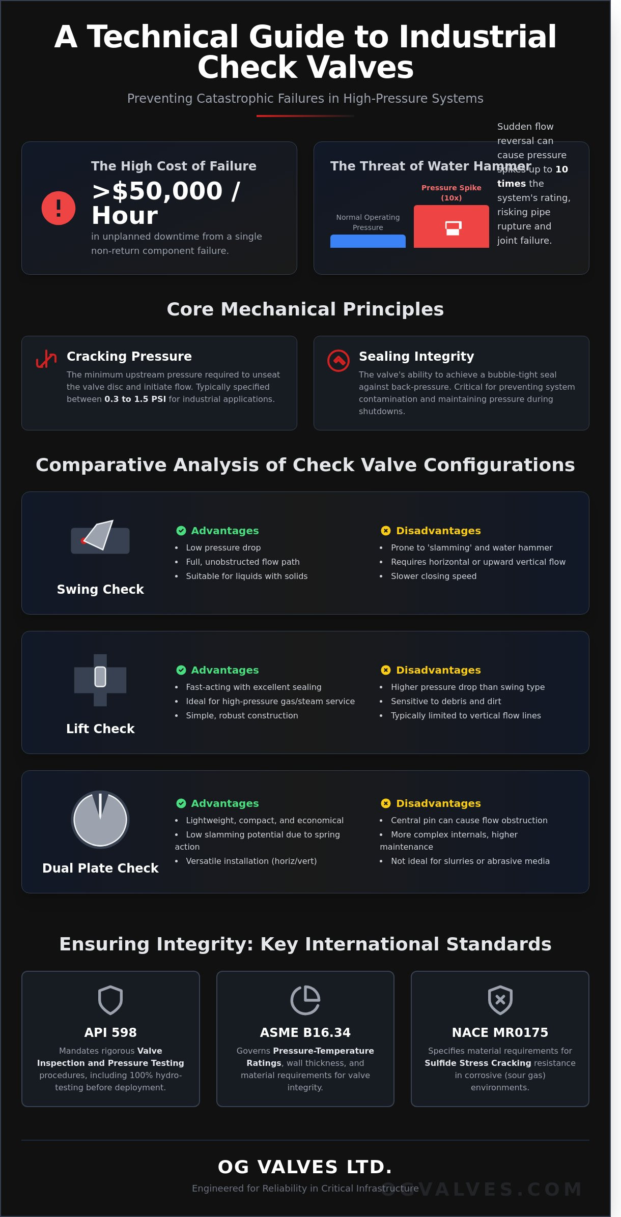
The failure of a single non-return component often results in catastrophic pump cavitation or irreversible structural fatigue costing industrial facilities upwards of $50,000 per hour in unplanned downtime. You recognize that maintaining consistent unidirectional flow is not merely a process requirement; it’s a fundamental safety protocol for high-pressure systems. Selecting the correct check valves is essential to mitigate backflow damage and water hammer in critical infrastructure projects scheduled for 2026.
This technical briefing provides a rigorous analysis of valve mechanics, focusing on the material integrity and mechanical design necessary to prevent premature failure in corrosive media. We’ll examine the specific engineering criteria required to protect pumps and compressors while ensuring full compliance with international safety mandates, including a comprehensive review of API 598 pressure testing, ASME B16.34 wall thickness requirements, and the performance characteristics of dual-plate versus piston-lift configurations.
Key Takeaways
Understand the critical role of self-actuating backflow prevention in safeguarding high-value assets like pumps and compressors.
Master the mechanical principles of check valves, including the precise calculation of cracking pressure and sealing integrity required for industrial flow control.
Evaluate the performance advantages of swing, lift, and dual-plate configurations to determine the optimal design for horizontal and vertical installations.
Identify the material specifications and international standards, such as NACE MR0175, necessary for maintaining structural integrity in corrosive environments.
Learn how strategic procurement and global logistics expertise can streamline inventory management to minimize industrial downtime during critical maintenance cycles.
The Fundamental Role of Check Valves in Industrial Flow Control
Industrial infrastructure relies on the mechanical integrity of check valves to maintain unidirectional flow within pressurized systems. These components function as self-actuating safety devices, requiring no external power source or manual intervention to operate. By utilizing the differential pressure of the process fluid, these valves automatically prevent backflow, a critical requirement for maintaining the operational life of rotating equipment. The mechanical principles of check valves dictate that the valve opens when the upstream pressure exceeds the downstream pressure and the internal spring force. Conversely, the valve closes as soon as the flow velocity decreases or reverses, creating a positive seal that isolates upstream components from downstream surges.
Failure to implement robust non-return mechanisms leads to catastrophic system damage. In high-capacity pumping stations, reverse flow can cause pumps to spin backwards at speeds exceeding 150% of their rated RPM, resulting in immediate bearing failure or shaft misalignment. Additionally, the sudden closure of fluid columns induces water hammer, a phenomenon capable of generating pressure spikes up to 10 times the steady-state operating pressure. This hydraulic shock compromises joint integrity and leads to localized pipe wall thinning or rupture. System contamination is another risk, where backflow introduces untreated or process-spent fluids into clean supply lines, violating safety protocols in water treatment or chemical processing sectors.
Primary Functions in High-Pressure Systems
In circuits operating at pressures exceeding 1,500 PSI, check valves serve three critical roles. They maintain system pressure during planned pump shutdown phases, preventing the total depressurization of the line. In vertical piping configurations, they prevent the drainage of fluid columns, which eliminates the risk of dry starts during the next duty cycle. Specialized valves also act as vacuum breakers in storage tanks to prevent structural collapse during rapid drainage. These functions ensure that the system remains primed and ready for immediate reactivation without manual priming.
Terminology and Engineering Standards
Engineers must specify the ‘cracking pressure’, which is the minimum upstream pressure, often measured in increments as low as 0.5 PSI, required to move the disc from its seat. Achieving a leak-tight shutoff depends on the reseat pressure, where the valve maintains a bubble-tight seal against back-pressure. All industrial-grade valves must comply with API 594, which dictates face-to-face dimensions and wall thickness, and ASME B16.34, governing pressure-temperature ratings. These standards ensure that forged steel or cast iron bodies meet the 100% hydro-testing requirements before deployment in critical infrastructure. Adherence to these codes is mandatory for maintaining the technical integrity of global oil and gas projects.
Mechanical Principles: Cracking Pressure and Sealing Integrity
Engineering check valves requires a precise understanding of the internal forces governing disc movement. The disc remains seated until the upstream pressure generates enough force to overcome the mechanical resistance, whether that originates from a spring constant or the gravitational weight of the disc assembly. If the flow velocity doesn’t reach the required threshold for the specific valve geometry, the disc won’t reach its full-open stop. This leads to increased pressure drop and turbulent flow patterns that can erode internal components over time.
Selecting the correct valve involves analyzing the industrial valve design and selection criteria, specifically regarding the minimum velocity required for full-disc lift. When the system operates below this velocity, the valve operates in a partially open state, which is a primary cause of premature failure in high-pressure systems. Engineers must calculate the force balance between the fluid’s kinetic energy and the valve’s internal resistance to ensure stable operation across the entire flow range.
Cracking Pressure Dynamics
Cracking pressure is a critical specification for spring-loaded designs. It’s the delta-P required to initiate flow based on the spring tension and the effective area of the disc. In most industrial applications, cracking pressures range from 0.3 PSI to 1.5 PSI, though specialized cryogenic or high-viscosity services may require higher thresholds. Low-flow conditions often lead to “chatter,” a state where the disc oscillates rapidly against the seat. This frequency can cause fatigue in hinge pins and accelerate seat wear. Cracking pressure is the precise differential at which the seal breaks.
Seating and Leakage Classifications
The integrity of the seal depends on the interface between the disc and the seat. Metal-to-metal seating, often utilizing Stellite or 13% Chrome, is standard for high-temperature service where durability is paramount. Resilient seats, using elastomeric materials like Viton or EPDM, provide bubble-tight shutoff but are limited by chemical compatibility and temperature. Compliance with API 598 leakage rates is the industry benchmark for testing these seals. During static conditions, back-pressure acts as a functional advantage; it reinforces the seal by pressing the disc tighter against the seat. For systems requiring zero-leakage performance, industrial check valves with soft-seat inserts are typically specified to ensure compliance with environmental and safety standards.
The physics of valve slam are rooted in the inertia of the moving fluid. As forward flow ceases, the fluid column begins to reverse direction. A standard swing check valve has a long travel distance and high disc mass, which often results in the disc remaining open as the reverse flow gains momentum. When the disc finally makes contact with the seat, it does so against a high-velocity stream, resulting in an instantaneous stop of the fluid. This converts kinetic energy into a massive pressure spike, often called water hammer. Nozzle-check designs address this by utilizing a lightweight disc and a short-stroke spring. These components allow the valve to close in as little as 0.05 to 0.15 seconds, effectively sealing the orifice before the reverse flow velocity can escalate.
Comparative Analysis of Industrial Check Valve Configurations
Selecting the appropriate configuration for check valves requires a rigorous assessment of the mechanical interaction between the closure element and the process media. Engineers must prioritize hydraulic efficiency and long-term seat integrity to ensure system safety. Each design offers distinct advantages regarding flow resistance, sealing capabilities, and installation orientation.
Swing Check Valves vs. Lift Check Valves
Swing check valves utilize a pinned disc that rotates away from the flow path on a hinge. This geometry provides a clear flow passage, resulting in a low pressure drop and a high coefficient of flow (Cv). They’re the standard choice for large-bore piping and systems with flow velocities below 3 meters per second. However, these valves aren’t suitable for pulsating flow. Constant turbulence causes the hinge pin to wear prematurely, leading to disc misalignment and seat failure.
Lift check valves employ a guided piston or disc that rises vertically from the seat. The internal body construction is robust, sharing design similarities with gate valves in terms of wall thickness and pressure-containing integrity. These units provide superior sealing for high-pressure gas services where leak-tight performance is mandatory. While they offer exceptional shut-off, the diverted flow path creates a higher delta-P than swing designs. Engineers typically specify lift checks for small-diameter, high-pressure applications where space allows for the vertical movement of the disc.
Dual Plate and Nozzle Check Innovations
Modern industrial requirements, particularly in the offshore sector, demand weight reduction and space efficiency. The dual plate ‘wafer’ design meets these needs by utilizing two spring-loaded plates hinged on a central pin. This configuration adheres to API 594 standards and reduces the valve’s total weight by approximately 75% to 85% compared to a standard flanged swing check. It’s a critical component for weight-sensitive platforms where every kilogram impacts structural costs.
For systems prone to water hammer, nozzle check valves serve as the premium non-slam solution. These valves use a venturi-shaped body and a short-stroke, spring-assisted disc to achieve closure in less than 0.2 seconds. By closing before the reverse flow velocity can build, nozzle check valves effectively eliminate pressure surges and protect sensitive downstream equipment like centrifugal pumps. Key performance factors include:
Mechanical Advantage: Spring-assisted closure in nozzle valves prevents disc slamming.
Installation Versatility: Dual plate valves function effectively in both horizontal and vertical orientations due to spring tension.
Maintenance: Swing checks offer easier accessibility through a bolted bonnet for periodic internal inspections without removing the valve body from the line.
Pressure Loss: Nozzle checks provide a streamlined flow path that recovers pressure efficiently, minimizing long-term energy costs in continuous pumping operations.
It’s vital to match the valve’s closing speed with the deceleration characteristics of the fluid column. A failure to synchronize these variables leads to catastrophic pipe rupture or valve housing failure. Clinical adherence to ASME B16.34 specifications during the selection process ensures the chosen configuration meets the mandatory pressure and temperature ratings for the specific industrial environment. Engineers specifying flow control components for large-diameter pipelines should also review the design and selection criteria for industrial butterfly valves to evaluate where quarter-turn isolation complements non-return protection in the same system.
Material Specifications and Compliance with International Standards
Material selection is a critical engineering requirement for industrial check valves. It’s a process driven by the chemical composition, pressure ratings, and thermal profiles of the process media. Engineers must account for specific corrosion rates and mechanical fatigue to ensure a 30-year design life in high-pressure environments. Failure to align metallurgy with fluid properties leads to premature valve failure and catastrophic system loss.
Common and Specialized Valve Alloys
The choice of alloy determines the valve’s operational envelope. Carbon steel, specifically ASTM A216 WCB, remains the standard for non-corrosive industrial services up to 425°C. For low-temperature applications reaching -46°C, ASTM A352 LCC is mandatory to maintain impact toughness. Austenitic stainless steels, such as CF8M, provide essential resistance in chemical processing involving acetic or phosphoric acids. In offshore environments where chloride concentrations exceed 19,000 ppm, Super Duplex (ASTM A890 Grade 5A) or Monel 400 is utilized to prevent pitting and stress corrosion cracking.
Regulatory Frameworks: API, ASME, and ISO
Adherence to international standards provides the baseline for valve integrity. API 6D serves as the primary specification for pipeline check valves, defining the rigorous testing and manufacturing requirements for full-opening designs. ASME B16.10 ensures dimensional interchangeability by standardizing face-to-face and end-to-end dimensions. Modern procurement protocols now frequently mandate ISO 15848-1 compliance to restrict fugitive emissions to levels below 50 ppm, reflecting a global shift toward environmental safety and leak prevention.
Since the 2015 update of the NACE MR0175/ISO 15156 standard, compliance is a non-negotiable requirement for sour gas environments where H2S partial pressures exceed 0.05 psi. This standard dictates strict hardness limits to prevent sulfide stress cracking. To mitigate erosive wear on seating surfaces, a hard-facing overlay, typically Stellite 6, is applied. This cobalt-based alloy maintains a hardness of approximately 40 HRC at elevated temperatures, resulting in a 40% increase in seat longevity compared to untreated surfaces.
Verification of these technical specifications is performed through Positive Material Identification (PMI) testing. Using X-ray fluorescence (XRF) analyzers, technicians confirm that the chemical heat analysis of the valve body and trim matches the Mill Test Report (MTR). This clinical approach to quality control eliminates the risk of material grade substitution during the manufacturing process. For facilities integrating automated flow control, correct industrial valve actuator sizing and environmental compatibility are equally critical factors that must be verified alongside material certification to prevent system failures. Projects that also incorporate butterfly valve seat integrity and API 609 compliance within the same pipeline system must apply the same rigorous PMI protocols to all pressure-retaining components.
For technical consultation on material selection for high-stakes infrastructure, explore our industrial valve solutions to ensure your project meets all regulatory benchmarks.
Procuring High-Performance Check Valves for Critical Infrastructure
OG VALVES LTD. integrates engineering precision with a robust global logistics framework. This dual approach ensures that procurement cycles for high-specification check valves align with strict project timelines. We maintain an extensive inventory of standard and specialty components to facilitate fast-track delivery. Minimizing industrial downtime remains a primary metric of our operational success; stock items typically undergo dispatch within 48 hours of order confirmation to prevent costly site delays.
Our quality assurance protocols are comprehensive and non-negotiable. Every unit passes through a rigorous validation process that begins with the verification of Mill Test Reports (MTRs). This ensures that the chemical and mechanical properties of the base materials meet ASME and ASTM standards. Final assessment involves hydrostatic and pneumatic shell and seat testing in accordance with API 598 or API 6D specifications. This clinical focus on compliance ensures that every valve performs reliably under its designated pressure and temperature rating, maintaining system integrity in volatile environments.
Optimising Procurement for Large-Scale Projects
Managing complex valve packages for petrochemical plants or power generation facilities requires precise technical coordination. Engineers benefit from our specialized support during the critical phases of sizing and material selection. We provide data-driven guidance on selecting alloys for corrosive service, such as Super Duplex or Monel 400. Documentation traceability is a mandatory requirement for safety-critical infrastructure. We supply comprehensive data books containing EN 10204 3.1 or 3.2 certification to ensure full audit compliance for every component within the package.
Global Delivery and Technical Support
Our logistics network supports the international supply of high-integrity flow control solutions to remote refineries and offshore platforms. OG VALVES LTD. provides technical consultation to address complex hydraulic challenges, specifically backflow prevention and the mitigation of water hammer. These phenomena can cause catastrophic pipe failure if the valve’s closing speed isn’t correctly synchronized with flow deceleration. You can request a quote for industrial check valves to secure high-integrity flow control that adheres to ISO 9001 quality management systems. Our team delivers the technical data required to finalize complex specifications without ambiguity, ensuring long-term performance in demanding industrial applications.
Optimizing Flow Integrity for 2026 Industrial Infrastructure
Selecting industrial check valves requires a rigorous assessment of cracking pressure and sealing integrity to prevent backflow in high-pressure environments. Engineers must prioritize components that meet the exact specifications of API 594 and ASME B16.34 to ensure long-term mechanical performance. It’s essential to align material grades with specific fluid dynamics to maintain system safety in oil, gas, and water treatment sectors. Successful flow control relies on the clinical application of these technical principles.
OG Valves maintains an extensive inventory of API and ASME compliant hardware designed for critical infrastructure. Our technical specialists provide the specialist technical expertise in heavy industry needed to manage complex installations. With fast-track global delivery protocols, procurement teams can meet tight 2026 project deadlines without compromising on quality. Our commitment to industrial precision ensures every valve undergoes testing to meet ISO 9001 quality management protocols. Relying on verified engineering standards reduces the risk of system failure and extends the operational lifecycle of your assets.
Your systems deserve the precision of world-class engineering.
Frequently Asked Questions
What is the primary difference between a swing check valve and a lift check valve?
The primary difference lies in the disc mechanism; swing check valves utilize a hinged disc that swings away from the seat, whereas lift check valves employ a piston or ball that rises vertically. Swing designs provide lower pressure drops in high-volume systems. Lift designs are better suited for high-pressure services like steam where flow rates exceed 3 meters per second. Both configurations must comply with ASME B16.34 standards to ensure pressure-temperature rating integrity and safety.
Can check valves be installed in vertical piping runs?
Check valves can be installed in vertical piping provided the flow direction is upward to ensure gravity assists in seating the disc. For downward vertical flow, engineers must specify spring-loaded designs to overcome gravitational force. Standard swing valves often fail in vertical downward orientations because the disc doesn’t seat properly. API 594 specifies the requirements for wafer check valves in these configurations to prevent backflow in 100% of vertical installations.
What causes a check valve to ‘chatter’ and how can it be prevented?
Valve chatter occurs when the flow rate is insufficient to hold the disc in a stable, fully open position, causing it to oscillate against the stops. This mechanical vibration leads to premature wear of the hinge pin and seat. To prevent this, maintain a minimum flow velocity of 1.5 meters per second. You’ve got to ensure the valve is positioned at least 5 pipe diameters away from pumps or elbows to reduce turbulence.
What is cracking pressure and why does it matter for pump protection?
Cracking pressure is the specific upstream pressure level where the valve disc first lifts from the seat to allow flow. It’s critical for pump protection because it ensures the pump doesn’t operate against a closed head, which can cause overheating within 120 seconds. Selecting a valve with a cracking pressure 10% below the pump’s minimum discharge pressure prevents cavitation. It’s a vital step for protecting the mechanical seals in centrifugal pumps.
What are the advantages of using a dual plate wafer check valve?
Dual plate wafer check valves offer a compact face-to-face dimension that is 80% lighter than traditional full-body swing valves. The twin-plate design reduces the closing distance, which minimizes the potential for water hammer and pressure surges. These valves provide a lower pressure drop across the system. They’re compliant with API 594 standards for refinery and petrochemical applications where space is limited and weight reduction is a priority.
How do I select the correct material for a check valve in a corrosive environment?
Selecting materials for corrosive environments requires adherence to NACE MR0175 or ISO 15156 standards for sour gas or chemical service. Engineers typically specify 316 Stainless Steel for general corrosion or Duplex 2205 for high-chloride environments. For acidic concentrations above 15%, Super Austenitic alloys or Nickel-based Monel provide the necessary surface integrity. Material test reports must verify the chemical composition of every pressure-retaining component to ensure long-term durability.
What standards govern the testing and leakage rates of industrial check valves?
Industrial check valves are tested under API 598 or ISO 5208 standards to define permissible leakage rates. API 598 specifies high-pressure hydrostatic and low-pressure pneumatic tests for seat integrity. Soft-seated valves must achieve Rate A or zero visible leakage during a 60-second test interval. Metal-seated valves have specific allowable leakage rates based on the nominal pipe size, often measured in drops per minute. These protocols ensure the reliability of check valves in critical infrastructure.
What is a non-slam check valve and when is it required?
A non-slam check valve is a spring-assisted valve designed to close rapidly before the fluid flow actually reverses. This prevents the disc from slamming against the seat, which eliminates the kinetic energy spike that causes water hammer. They’re required in systems where sudden pump failure could cause a pressure surge exceeding 500 PSI. These valves utilize high-tension springs to ensure the disc closes in approximately 0.2 seconds, protecting the piping infrastructure.
 Responsive Menu