Valve Actuator Sizing: A Technical Guide for Industrial Engineering Specifications (2026)
April 07, 2026
Home+Valve Actuator Sizing: A Technical Guide for Industrial Engineering Specifications (2026)
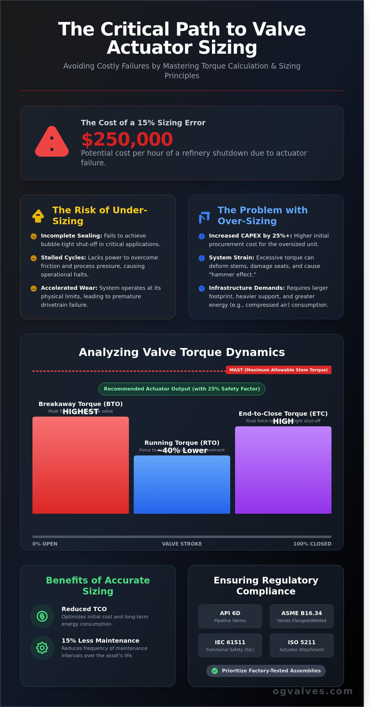
A 15% error in torque calculation during the valve actuator sizing process is frequently the difference between operational integrity and a $250,000 per hour refinery shutdown. This technical reality dictates that relying on generic manufacturer data is an unacceptable risk for critical industrial applications. You’ve likely encountered the frustration of inaccurate torque profiles that don’t account for breakaway requirements or fluid viscosity changes in high-pressure systems. These inaccuracies lead to costly downtime and compromise the safety of your entire infrastructure.
It’s essential to move beyond guesswork to ensure your systems meet the rigorous demands of 2026 engineering standards. You’ll master the technical requirements and calculation frameworks necessary to precisely size valve actuators for critical industrial applications. This guide provides a repeatable methodology for ensuring your valve actuator sizing aligns with API 6D and ASME B16.34 standards. We’ll analyze the specific safety factors and data points required to establish long-term reliability in forged steel and cast iron assemblies while maintaining full regulatory compliance.
Key Takeaways
Differentiate between Breakaway, Running, and Seating torque requirements to ensure mechanical integrity across the entire operational stroke.
Implement a standardized engineering framework for valve actuator sizing that integrates verified torque data with site-specific power supply constraints.
Mitigate the risks of “stiction” and seat bonding through the application of rigorous safety factors tailored to specific fluid properties and thermal conditions.
Validate procurement specifications by prioritizing factory-tested assemblies and comprehensive material traceability to meet international compliance standards.
The Critical Importance of Precision in Valve Actuator Sizing
The Valve actuator serves as the definitive mechanical interface between automated control logic and the physical dynamics of fluid flow. It’s the component responsible for converting signal energy into the torque or thrust required to manipulate a valve’s closure element. Precise valve actuator sizing is a non-negotiable requirement for maintaining process control and facility safety. When an actuator is under-sized, it lacks the necessary force to overcome internal friction and process pressure. This results in stalled cycles, incomplete sealing, and a failure to achieve the 100% bubble-tight shut-off required in high-pressure gas applications. Mechanical components experience accelerated wear as the system operates at the edge of its physical limits, often leading to premature failure of the drive train.
Over-sizing presents a different set of engineering challenges that impact the project’s bottom line. Selecting an actuator that’s significantly larger than the application requires can increase Capital Expenditure (CAPEX) by 25% or more. These larger units demand a greater physical footprint and heavier mounting hardware, which complicates piping design and structural support requirements. In pneumatic systems, over-sized cylinders consume excessive volumes of compressed air; this forces an increase in the capacity of the plant’s air infrastructure. Engineering specifications must also account for Safety Integrity Level (SIL) ratings. Alignment with IEC 61511 standards ensures that the selected actuator provides the functional reliability necessary for critical safety functions.
The Relationship Between Actuation and System Integrity
Precise sizing is essential to prevent mechanical fatigue in valve stems and seating surfaces. Excessive torque from an over-powered actuator can deform the stem or damage the internal seats during high-cycle operations. In Emergency Shutdown (ESD) scenarios, the actuator must provide enough force to close the valve against the maximum possible differential pressure. This level of precision ensures full compliance with A Technical Guide to Industrial Gate Valves and ISO 5211 mounting standards. Maintaining this integrity is vital for preventing fugitive emissions and ensuring the long-term reliability of the pressure boundary.
Economic Drivers for Accurate Specification
Total Cost of Ownership (TCO) is the primary economic metric in valve actuator sizing. Accurate torque matching reduces the frequency of maintenance intervals by approximately 15% over the life of the asset. It eliminates the “hammer effect” caused by over-powered units, which often leads to seat degradation. By optimizing the specification, engineers reduce both the initial procurement cost and the long-term energy consumption of the control system. This technical rigor ensures that the facility operates with maximum efficiency while adhering to the most stringent industrial safety protocols.
Analysing Valve Torque Dynamics: Breakaway, Running, and Seating
Accurate valve actuator sizing requires a granular analysis of torque requirements across the entire stroke. Engineers must calculate three distinct torque values to ensure operational integrity under maximum service conditions. Breakaway Torque (BTO) represents the peak force needed to move the closure element from the seated position. It accounts for static friction and the “unseating” force caused by differential pressure. Running Torque (RTO) is the dynamic force required to maintain movement through the mid-stroke. For most ball valves, RTO is significantly lower than BTO, often dropping by 40% once the seal is broken. End-to-Close Torque (ETC) is the final force required to re-seat the valve and achieve a bubble-tight shut-off against full system pressure.
Safety protocols dictate the identification of the Maximum Allowable Stem Torque (MAST). This value represents the mechanical limit of the valve stem. If the actuator’s output exceeds the MAST, the stem may suffer plastic deformation or total shear. Engineers typically apply a 25% safety factor when matching actuator output to valve requirements, ensuring the actuator is powerful enough to operate the valve but remains below the MAST threshold. For complex installations, utilizing a standardized actuator selection and sizing framework ensures that these calculations align with empirical data and mechanical limits.
Quarter-Turn vs. Multi-Turn Torque Profiles
Torque curves for ball and butterfly valves are non-linear. The peak occurs at the start and end of the stroke where seat friction is highest. In contrast, gate and globe valves require linear thrust. Converting this thrust to torque involves calculating the stem diameter and thread pitch. Metal-seated valves, often utilizing Stellite or 316 Stainless Steel, have higher friction coefficients than soft-seated PTFE variants. This necessitates larger actuators for metal-to-metal contact scenarios common in high-temperature service.
The Impact of Differential Pressure (Delta P)
Differential pressure is the primary driver of torque demand. It exerts a perpendicular force against the closure element, increasing the friction between the seat and the disc or ball. Following ASME B16.34 standards, sizing must account for the “worst-case” scenario, such as a full pressure drop across the valve during a pump failure. A Class 600 valve, rated for 102.1 bar at 38°C, requires significantly more torque than a Class 150 equivalent. You can review detailed industrial valve specifications to determine the exact Delta P requirements for your specific alloy and pressure class. These calculations prevent stalling during critical emergency shutdown (ESD) sequences.
A Step-by-Step Engineering Framework for Actuator Calculation
Executing precise valve actuator sizing is a critical requirement for maintaining plant integrity and preventing operational downtime. The process begins with the acquisition of certified torque data from the valve manufacturer. This data must specify torque requirements at the break-to-open, running, and seating positions under maximum differential pressure (ΔP) conditions. Engineers shouldn’t rely on nominal values, as media viscosity and temperature significantly alter the torque profile.
Step 1: Obtain torque charts specific to the valve’s material grade and seat type under full ΔP.
Step 2: Define the minimum available power supply, accounting for voltage drops in electric lines or pressure losses in pneumatic headers.
Step 3: Apply a safety factor (SF) that reflects the criticality of the application and the nature of the process media.
Step 4: Validate the mechanical interface by cross-referencing ISO 5211 or MSS SP-101 mounting patterns for structural alignment.
Defining the Safety Factor (SF)
A 20% to 30% safety margin serves as the industrial baseline for standard service. This margin compensates for seat wear and packing friction over time. For high-cycle applications exceeding 10,000 cycles per year or Safety Instrumented Systems (SIS), an SF of 50% is mandatory to ensure reliability. The objective is to verify that the Actuator Torque Output (ATO) always remains higher than the Valve Torque Requirement (VTR). Consulting a technical guide to actuator sizing provides the necessary formulas to reconcile these variables with specific rack-and-pinion or scotch-yoke geometries.
Power Source Variability
Pneumatic sizing must be calculated at the lowest possible supply pressure. A 15% reduction in PSI can lead to a proportional loss in torque, potentially stalling the valve. Electric actuator specifications require a rigorous review of duty cycles, typically rated between 25% and 50% for intermittent service. Continuous operation beyond these limits triggers thermal protection circuits, halting the process. Hydraulic systems offer superior torque density, with some units delivering over 700,000 Nm for heavy-duty pipeline service, yet they demand strict compliance with fluid cleanliness standards to prevent seal degradation. For applications where this level of force is critical, understanding the full capabilities of a hydraulic valve actuator is essential to matching the right technology to your high-pressure isolation requirements. Engineers evaluating the trade-offs between power source technologies should also review a detailed pneumatic vs electric actuator comparison to assess torque characteristics, duty cycle limitations, and fail-safe performance across different supply conditions.
Finalizing the valve actuator sizing involves checking the stem diameter and keyway dimensions against the actuator’s drive bush. If the mounting flange doesn’t align with ISO 5211 standards, custom bracketry must be engineered to withstand the reactionary forces generated during high-torque seating events. This prevents structural deflection that causes premature packing leaks or stem galling.
Mitigating Risk: Safety Factors and Process Media Considerations
Accurate valve actuator sizing requires a safety margin that accounts for the inevitable degradation of performance over time. Engineers must calculate the Running Torque and Break-to-Open Torque under worst-case scenarios; this includes the stiction effect where the valve disc or ball bonds to the seat during periods of dormancy. In high-temperature systems exceeding 200°C, thermal expansion of forged steel or stainless steel components increases mechanical interference. This necessitates a safety factor multiplier, typically ranging from 1.25 to 1.5, to ensure reliable cycling. When managing particulate matter or abrasive slurries in mining or wastewater operations, the presence of solids increases the torque required to shear through the media. A 25% torque buffer is the industry standard for these applications to prevent actuator stall conditions.
Media Influence on Friction Coefficients
The nature of the process fluid dictates the friction coefficient between the sealing surfaces. Lubricating media like refined hydrocarbons reduce torque requirements by 15% to 20% compared to dry, non-lubricating gases. Conversely, high-viscosity fluids such as heavy crude or polymer flows create hydraulic drag that taxes the actuator’s output. Scale build-up from hard water or corrosive media increases surface roughness on the ball or disc. It’s critical that sizing accounts for the aged condition of the valve, where torque often rises by 30% after 24 months of continuous service in aggressive environments. It doesn’t matter if the valve is new; the specification must reflect the end-of-life torque requirements to maintain system integrity.
Environmental and Operational Variables
Ambient conditions directly impact actuator integrity and performance. Pneumatic seals often lose elasticity at temperatures below -29°C, which increases internal leakage and reduces effective thrust. In hazardous zones, compliance with ATEX or IECEx standards is mandatory for housing selection to prevent ignition risks. Engineers seeking a comprehensive overview of industrial valve actuator automation and control specifications, including ATEX and IECEx certification protocols, will find detailed guidance on matching pneumatic, electric, and hydraulic units to hazardous area requirements. Mounting orientation is another critical factor that engineers frequently overlook. Vertical installations on large-diameter pipelines can increase bearing loads by 15% due to the overhung weight of the actuator. This necessitates reinforced mounting kits and specific bearing selections to maintain alignment and prevent premature seal failure. Rigorous adherence to these variables ensures that the selected unit provides the necessary torque across its entire 10,000-cycle design life.
Integrating Actuator Selection into Large-Scale Industrial Procurement
Procurement of automated valve systems requires a shift from component-based purchasing to integrated assembly sourcing. Procuring valves and actuators as factory-tested units eliminates torque mismatching and mounting errors. This strategy ensures the valve actuator sizing remains accurate within the final operational environment. When assemblies are sourced from disparate vendors, the risk of technical misalignment increases, often leading to site-side failures during commissioning. A unified procurement model reduces these risks by providing a single point of accountability for the entire automation package.
Critical service applications demand 100% material traceability. Positive Material Identification (PMI) must be performed on all pressure-retaining components and mounting hardware to verify alloy composition. In high-pressure oil and gas environments, the use of forged steel or specific stainless steel grades prevents premature fatigue. Standardizing actuator models across a 500-valve facility can reduce spare parts inventory by 30%. It simplifies maintenance training and streamlines emergency repairs. Technical specifications should prioritize manufacturers who maintain high-specification inventory to minimize project lead times. While custom-engineered assemblies often require 24 weeks for delivery, leveraging fast-track global supply chains can reduce this timeline to 8 weeks or less. Facility managers evaluating long-term infrastructure costs should consider a thorough pneumatic vs electric actuator technical comparison to determine which technology delivers the optimal balance of Total Cost of Ownership and fail-safe reliability across their specific operating conditions.
Quality Assurance and Documentation
Every automated valve package must undergo Factory Acceptance Testing (FAT) before site delivery. This process includes cycle testing, leak rate verification, and fail-safe performance checks under simulated load conditions. Documentation must adhere to EN 10204 3.1 or 3.2 standards to ensure full material and mechanical compliance. These certifications provide a mandatory audit trail for engineering integrity. OG Valves provides the technical verification and logistical support needed to maintain these rigorous standards across global infrastructure projects, ensuring that every valve actuator sizing calculation is backed by empirical test data.
Next Steps for Engineering Procurement
Complex actuation requirements, particularly for cryogenic or high-pressure steam service, require validation from technical specialists. For emergency shutdown applications demanding sub-second response times and extreme torque output, engineers should evaluate hydraulic valve actuator solutions engineered to ISO 12490 standards as part of their technology selection process. Project managers should utilize global inventory systems for the rapid deployment of high-specification components. This ensures compliance with API 6D and ISO 5211 standards without compromising project schedules. Precision in procurement prevents the high costs associated with downtime and mechanical failure. To begin your technical evaluation, request a technical consultation for your valve actuation project.
Securing Operational Integrity Through Advanced Specification
Effective valve actuator sizing demands a clinical focus on torque dynamics and mechanical safety factors to prevent catastrophic system failure. This 2026 technical framework emphasizes that breakaway, running, and seating torque must be calculated against specific process media variables to ensure 100% operational reliability. Adherence to API 6D and ASME B16.34 standards isn’t optional; it’s the foundation of industrial safety. OG Valves maintains a global supply chain presence across 52 countries, providing the rigorous engineering oversight required for high-stakes oil, gas, and water treatment projects. Our team delivers 24/7 technical support for heavy industry sectors, ensuring that every actuator selection meets the precise requirements of the most demanding environments. By prioritizing these clinical data points, procurement specialists can mitigate risk and extend the service life of critical infrastructure components. We’re ready to assist with your next technical specification to ensure your systems perform at peak capacity. Consult with OG Valves Technical Specialists for Precision Actuator Sizing to secure your project’s engineering excellence.
Frequently Asked Questions
What is the standard safety factor for valve actuator sizing?
The standard safety factor for valve actuator sizing ranges from 20% to 50% above the maximum measured torque of the valve. This margin accounts for friction increases caused by seat wear or media accumulation over a five year service cycle. Engineers typically specify a 1.25 multiplier for clean liquids and a 1.5 multiplier for slurry or high-viscosity media to ensure reliable operation under adverse conditions.
How does differential pressure affect actuator torque requirements?
Differential pressure directly increases the seating and unseating torque by forcing the closure element against the seat with greater intensity. In a 150mm ball valve, a 10 bar increase in differential pressure can elevate the required breakaway torque by 15%. Accurate valve actuator sizing requires calculating torque at the maximum expected differential pressure rather than nominal operating pressure to prevent stall conditions during critical cycles.
What is the difference between breakaway torque and running torque?
Breakaway torque’s the peak force required to initiate movement from the fully closed or open position, while running torque’s the lower force needed to maintain motion during the stroke. For a standard API 6D gate valve, breakaway torque’s typically 2.5 times higher than the dynamic running torque. Sizing must account for this initial peak to ensure the actuator can overcome static friction and differential pressure loads.
Can I use a pneumatic actuator if my air pressure fluctuates?
You can utilize a pneumatic actuator with fluctuating air pressure if you size the unit based on the minimum recorded supply pressure. If your plant air ranges from 4 bar to 7 bar, the actuator must be sized to generate the required torque at 4 bar. Sizing for the 7 bar peak risks insufficient force during pressure drops, while sizing for the 4 bar minimum ensures 100% operational reliability.
How do I calculate the MAST (Maximum Allowable Stem Torque)?
Calculate the Maximum Allowable Stem Torque (MAST) by multiplying the material’s shear stress limit by the polar section modulus of the valve stem. For a 316 stainless steel stem, this involves using the 0.2% yield strength as defined in ASTM A276. You’ve to ensure the actuator’s maximum output torque at its highest supply pressure doesn’t exceed 90% of the calculated MAST to prevent mechanical failure or stem deformation.
Why is ISO 5211 important for actuator mounting?
ISO 5211 is critical because it standardizes the flange dimensions and drive component interfaces between the valve and the actuator. This 2017 standard defines specific bolt circle diameters and pilot dimensions, such as the F07 or F10 patterns, ensuring mechanical compatibility across different manufacturers. Adherence to ISO 5211 eliminates the need for custom mounting kits, reducing procurement lead times by 30% for global infrastructure projects.
Does the media temperature affect the sizing of the actuator?
Media temperature influences actuator sizing by altering the friction coefficient of seat materials like PTFE or metal. At cryogenic temperatures below -150 degrees Celsius, torque requirements can increase by 40% due to material contraction and lubricant hardening. Conversely, high-temperature service exceeding 250 degrees Celsius may require extended mounting brackets to protect the actuator’s electronic or pneumatic seals from thermal degradation and premature failure.
What are the risks of over-sizing an electric actuator?
Over-sizing an electric actuator creates a high risk of shearing the valve stem if an obstruction occurs; the motor’s torque output simply exceeds the stem’s mechanical limits. This excessive force causes rapid wear on seat components and gearboxes, which can reduce the valve’s service life by 25%. Precision in valve actuator sizing prevents these mechanical failures and ensures torque switches function correctly within their calibrated 10% to 90% ranges.
 Responsive Menu