Comprehensive Guide to Hydraulic Valve Actuators in Industrial Applications (2026)
April 12, 2026
Home+Comprehensive Guide to Hydraulic Valve Actuators in Industrial Applications (2026)
In high-stakes industrial environments, a 0.5-second delay in emergency shutdown response represents the difference between contained pressure and catastrophic infrastructure failure. You’re likely aware that maintaining seal integrity and achieving precise high-torque isolation in high-pressure environments remains a constant engineering challenge for your technical team. Integrating a high-performance hydraulic valve actuator is the most reliable method for managing these critical variables while ensuring total system safety.
This technical deep-dive provides the exact selection criteria and mechanical specifications required to align your infrastructure with the rigorous ISO 12490 standards. We’ll examine precise torque calculations, specific material grades for corrosive service, and the optimization of fail-safe response times. By the end of this analysis, you’ll have the quantifiable data necessary to enhance system reliability and minimize costly unplanned downtime throughout your 2026 project cycle. Our focus remains on the clinical application of engineering principles to ensure your operations meet the highest global safety benchmarks.
Key Takeaways
Analyze the mechanical advantages of fluid incompressibility to achieve superior precision and rapid fail-safe response times in high-torque industrial environments.
Distinguish between linear and rotary conversion methods, including scotch yoke and rack and pinion designs, to optimize automation for diverse valve architectures.
Master the technical parameters required to accurately specify a hydraulic valve actuator, including torque requirements, operating pressure, and cycle frequency.
Implement rigorous maintenance protocols and diagnostic techniques to mitigate common failure modes and ensure long-term operational integrity.
Select appropriate material grades and configurations for extreme services to ensure adherence to international standards for cryogenic, high-temperature, and sour gas applications.
Fundamentals of Hydraulic Valve Actuation
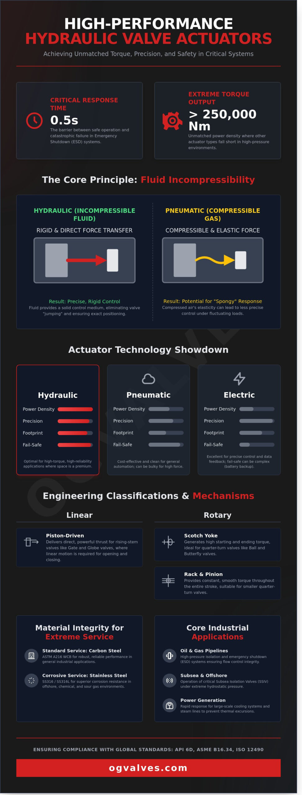
A hydraulic valve actuator serves as a robust fluid-driven mechanical device engineered for the automation of large-scale industrial valves. Hydraulic actuation is the conversion of fluid pressure into controlled mechanical force for high-torque valve operation. These systems are essential when mechanical requirements exceed 250,000 Nm, a threshold where electric or pneumatic alternatives often fail to provide the necessary power density. Engineers frequently reference Valve actuator fundamentals to establish baseline requirements for torque and stroke length in heavy-duty service. The core design integrates forged steel cylinders, chrome-plated pistons, and complex control manifolds that regulate fluid distribution with clinical precision.
The assembly relies on a closed-loop system where hydraulic fluid, typically a high-grade mineral oil, is pressurized to move a piston. This movement generates either linear or rotary force depending on the valve type. It’s a standard requirement for large-bore valves in high-pressure environments where manual operation is physically impossible. The internal components must meet rigorous material specifications to prevent fatigue under cyclical loading. This ensures the hydraulic valve actuator maintains its functional integrity over a service life that often spans several decades in demanding infrastructure projects.
The Role of Incompressible Fluids in Valve Control
Hydraulic oil provides a rigid control medium that eliminates the elasticity inherent in compressed air systems. Because liquids are virtually incompressible, the actuator provides linear or rotary motion without the risk of valve jumping. This stability is vital for modulating control valves where precise positioning is required to maintain flow integrity. The high power density of hydraulic systems means a smaller actuator produces significantly more force than a pneumatic unit of the same dimensions. Industrial facilities utilize this advantage to minimize the footprint of valve assemblies on offshore platforms and cramped refinery modules. It’s the primary reason why hydraulic systems are preferred when space is limited but torque requirements are extreme.
Core Applications in Heavy Industry
The deployment of a hydraulic valve actuator is standard practice in environments requiring extreme reliability and fail-safe functionality. These units are critical for subsea isolation valves (SSIV) and emergency shutdown systems (ESD), where they must operate under high hydrostatic pressure. In the power generation sector, they manage cooling systems that require immediate response times to prevent thermal excursions. Integration with specialised gate valves ensures leak-proof isolation in high-pressure oil and gas pipelines. Engineers don’t overlook the necessity of compliance with API 6D and ASME B16.34 standards during the selection process. These certifications ensure the assembly withstands the rigorous demands of 24/7 industrial operations without risk of mechanical failure.
Engineering Classifications: Linear vs Rotary Hydraulic Actuators
The selection of a hydraulic valve actuator depends on the mechanical requirements of the valve stem. Industrial systems categorize these units based on whether they produce linear thrust or rotary torque. Beyond motion type, engineers must specify the drive configuration. Double-acting actuators utilize hydraulic fluid for both opening and closing cycles. Spring-return or fail-safe configurations use fluid for one direction and a mechanical spring for the other. This ensures the valve reaches a predetermined safe position during a power loss.
Mechanical conversion methods vary based on the required output profile. Common designs include:
Scotch Yoke: Ideal for high-torque rotary applications.
Rack and Pinion: Provides constant torque for smaller quarter-turn valves.
Vane Actuators: Offer a compact footprint for limited-space rotary installations.
Piston-Driven Linear: Delivers direct force for rising-stem valves.
Material integrity is non-negotiable in high-pressure environments. Standard cylinders often utilize ASTM A216 WCB carbon steel. For offshore or chemical processing where corrosion is a factor, SS316 or SS316L stainless steel is the engineering standard. These materials ensure compliance with ISO 12944 atmospheric corrosivity categories, preventing structural failure in salt-heavy or acidic air.
Rotary Actuation and the Scotch Yoke Mechanism
The scotch yoke mechanism is the industry standard for automating large-scale ball and butterfly valves. It’s designed to convert the linear force of a hydraulic piston into a rotary movement. This design is preferred because it generates high break-to-open torque. It matches the torque demand curve of a ball valve, which is highest at the start of the stroke. Engineers choose between symmetric and canted yoke geometries. A symmetric yoke provides a balanced torque output at both ends of the stroke. A canted yoke shifts the peak torque to the start of the opening cycle. This is critical for valves in high-differential pressure service where “stiction” is a common failure point. Most units are tested to API 6D standards to ensure performance in critical pipeline infrastructure.
Linear Actuators for Gate and Globe Valves
Linear actuators provide the direct thrust needed for rising stem valves like gate and globe designs. In these applications, the hydraulic valve actuator moves the piston vertically to seat or unseat the valve disc. Sizing these units requires precise calculations of thrust. For example, a 12-inch Class 900 gate valve in high-pressure oil service must overcome both process pressure and packing friction. If the thrust isn’t calculated to ASME B16.34 standards, the valve won’t achieve a bubble-tight shut-off. Precision is maintained through stroke length limiters and integrated limit switches. These components provide real-time feedback to the control room, ensuring the valve isn’t over-torqued. If you’re managing a project with complex thrust requirements, you can view our engineering specifications for heavy-duty linear solutions. These systems are often integrated with API 598 testing protocols to verify seat integrity under full operational load.
Strategic Comparison: Hydraulic vs Pneumatic and Electric Actuation
Selecting the optimal hydraulic valve actuator requires a technical evaluation of power density, response speed, and environmental resilience. In heavy-scale industrial projects, the choice between hydraulic, pneumatic, and electric systems isn’t merely a matter of preference; it’s a decision based on the physical limits of the energy medium. Hydraulic systems operate at pressures reaching 210 bar or higher, providing a power-to-weight ratio that pneumatic systems, typically capped at 7 to 10 bar, cannot match. This allows for the installation of compact units on large-bore valves where a pneumatic equivalent would require a cylinder diameter exceeding the available footprint. For a comprehensive technical comparison of pneumatic, electric, and hydraulic industrial valve actuators across automation and control applications, engineers should evaluate each power source against the specific torque and environmental demands of their facility.
Infrastructure requirements also dictate the selection process. Pneumatic systems rely on centralized air compressors that are prone to leaks and energy loss, often losing up to 30% of their efficiency to thermal dissipation and piping friction. In contrast, Hydraulic Power Units (HPUs) provide a closed-loop system. This prevents internal corrosion and ensures that the actuator remains isolated from atmospheric contaminants. For hazardous area certifications like ATEX or IECEx, hydraulic units offer a simplified path to compliance. They don’t generate the electrical sparks or heat associated with electric motors, making them the standard for Zone 0 and Zone 1 environments in the oil and gas sector.
Performance Metrics and Power Density
Hydraulic systems excel in power density, delivering up to 250,000 Nm of torque in a package 60% smaller than pneumatic alternatives. This stiffness is critical for throttling applications in high-flow systems. Because hydraulic fluid is incompressible, it eliminates the “stick-slip” effect common in pneumatic cylinders. This results in precise positioning within 0.5% of the stroke length. For high-cycle industrial applications, the energy efficiency of hydraulics is superior, as the system only draws significant power during the actual movement of the valve, unlike electric units that may require constant cooling or anti-condensation heating.
Fail-Safe Reliability and Emergency Response
Safety protocols in 2026 demand rapid emergency shutdown (ESD) capabilities that electric actuators often struggle to provide. A hydraulic valve actuator equipped with a spring-return mechanism ensures immediate closure during a total power loss. While electric systems rely on backup batteries or supercapacitors, these components have limited lifespans and fail in temperatures below -15°C. Hydraulic accumulators solve this by storing mechanical energy in a pressurized bladder. This stored energy allows the valve to complete 3 to 5 full cycles even if the HPU is offline. In critical subsea or pipeline applications, hydraulic systems can close a 36-inch valve in under 2 seconds, a benchmark that ensures compliance with rigorous SIL 3 safety standards.
Operational Integrity: Maintenance and Regulatory Compliance
Maintaining a hydraulic valve actuator requires a disciplined approach to fluid chemistry and mechanical alignment. System failure often stems from three primary modes: internal fluid bypass across piston seals, external high-pressure leaks at the cylinder glands, or lateral valve stem misalignment. These issues compromise the torque delivery and response time of the assembly. Regular inspections must prioritize seal integrity, as even a 5-micron particulate can score cylinder walls and induce bypass. Precision alignment checks prevent side-loading on the valve stem, which otherwise leads to packing failure and increased breakout torque requirements.
Fluid Management and HPU Maintenance
The hydraulic power unit (HPU) serves as the heart of the actuation system. Precision filtration to ISO 4406 standards, typically achieving a 16/14/11 cleanliness level, is essential to prevent component wear. Moisture control through desiccant breathers or vacuum dehydration prevents fluid oxidation and acid formation. Technicians should monitor HPU pressure stability daily; a variance exceeding 5% often indicates pump cavitation or an accumulating nitrogen pre-charge leak in the bladder. High-temperature environments accelerate fluid degradation, necessitating thermal stability testing every 6,000 operational hours to prevent varnish buildup. It’s vital to maintain these units within their specified thermal and pressure envelopes to ensure long-term reliability.
Certification and Safety Standards
Compliance with international benchmarks ensures that the hydraulic valve actuator meets the rigorous demands of hazardous service. ISO 12490 defines the specific requirements for actuator performance in pipeline valves, while ASME B16.34 and API 6D govern the pressure-temperature ratings and testing protocols for the valve-actuator assembly. API 600 standards provide additional guidance for steel gate valves, ensuring that the actuator’s mechanical interface doesn’t compromise the valve’s pressure-containing capability. Material traceability documentation, including Mill Test Reports (MTRs) for forged components, remains a non-negotiable requirement for high-pressure installations.
Rigorous testing includes hydrostatic shell tests at 1.5 times the maximum rated pressure to confirm structural integrity. SIL 3 certification is often mandatory for hydraulic actuators used in critical emergency shutdown loops. Selecting hardware that meets these safety integrity levels reduces the Probability of Failure on Demand (PFD) and ensures compliance with IEC 61508 standards. Documentation for every unit must include pressure test certificates and functional test reports to verify that the assembly operates within the specified closing times and torque limits.
For technical assistance with compliance documentation or to review specific engineering data, contact the specialists at OG Valves.
Specifying Hydraulic Actuators for Critical Infrastructure
Specifying a hydraulic valve actuator for high-integrity systems demands a clinical evaluation of operational variables. Accurate sizing begins with the calculation of break-to-open (BTO), running, and end-to-close (ETC) torque values. These figures must be measured against the minimum available hydraulic supply pressure, which typically ranges from 100 to 210 bar in heavy industrial circuits. A 15% error in torque calculation during the valve actuator sizing process is frequently the difference between operational integrity and a costly unplanned shutdown. Cycle frequency is equally vital; high-cycle applications require reinforced seal geometries and heat dissipation analysis to prevent fluid degradation and mechanical wear.
Material selection is dictated by the service environment. For sour gas applications, all pressure-containing components must comply with NACE MR0175/ISO 15156 standards to mitigate sulfide stress cracking. Cryogenic services operating at temperatures as low as -196°C necessitate the use of 316 stainless steel or LCC/LCB grade steels with extended bonnets. Rigorous validation protocols ensure these materials perform under stress. This includes Positive Material Identification (PMI), hydrostatic testing at 150% of the maximum operating pressure, and functional performance tests to verify stroke timing. Procurement strategies prioritize the use of standardized forged components to reduce lead times, often shortening delivery windows by 25% for global infrastructure projects.
Integration with Industrial Valve Types
Actuator selection must align with the specific torque curve of the valve. Ball valves exhibit peak torque requirements during the initial break-away and final seating phases. Butterfly valves face dynamic torque challenges, where fluid velocity creates maximum resistance when the disc is at a 60 to 70 degree angle. We ensure mechanical compatibility by adhering to ISO 5211 mounting standards for top-works dimensions. Integration also involves the selection of critical accessories. Positioners, solenoid valves, and Partial Stroke Testing (PST) devices are integrated to allow for safety verification without interrupting process flow. These components ensure the hydraulic valve actuator functions reliably within a Safety Instrumented System (SIS).
The OG VALVES Approach to Technical Supply
OG VALVES manages technical supply through a framework of engineering precision and logistical efficiency. Our team conducts exhaustive compatibility reviews to ensure that actuator output never exceeds the maximum allowable stem torque (MAST) of the valve. This prevents catastrophic stem failure during high-pressure cycles. We utilize a global logistics network to facilitate fast-track delivery to offshore platforms and remote industrial sites, where downtime costs can exceed $50,000 per hour. Quality control isn’t a secondary process; it’s the foundation of our operations. Every unit is documented with full traceability, complying with API 6D and CE/PED requirements. We don’t just supply hardware; we provide certified reliability for the world’s most demanding fluid control environments.
Optimizing Industrial Control and Infrastructure Integrity
Selecting the appropriate hydraulic valve actuator remains a critical decision for maintaining operational safety and engineering precision through 2026. Industrial data indicates that hydraulic systems provide up to 25 times the power density of pneumatic alternatives, making them indispensable for high-torque applications in the oil and gas sectors. Engineers must prioritize API 6D and ISO 5211 compliance to ensure seamless integration with existing valve architectures. Rigorous adherence to documented maintenance protocols prevents catastrophic failures and extends the service life of critical infrastructure components by approximately 40% compared to neglected systems. It’s essential to evaluate equipment based on quantifiable performance metrics and verified material certifications.
OG Valves maintains an extensive inventory of ISO and API compliant actuators ready for immediate deployment. Our specialist technical support teams provide the engineering depth required for complex heavy industry projects. We leverage global fast-track delivery capabilities to minimize downtime and support large-scale industrial demands across six continents. For precise specifications tailored to your facility’s requirements, Request a Technical Quote for Hydraulic Actuators today. We look forward to securing your project’s long-term performance and reliability.
Frequently Asked Questions
What are the primary advantages of a hydraulic valve actuator over a pneumatic one?
A hydraulic valve actuator provides superior power density compared to pneumatic systems; it generates up to 250 bar of operating pressure. This incompressible fluid medium allows for precise positioning and eliminates the “stick-slip” effect found in compressed air systems. In high-torque applications exceeding 500,000 Nm, hydraulic units maintain a smaller physical footprint than pneumatic equivalents. This efficiency reduces the structural support requirements for the valve assembly.
How do you calculate the required torque for a hydraulic actuator?
To calculate the required torque, multiply the valve’s breakaway torque by a safety factor of at least 1.25 to account for friction and seating forces. The formula involves the effective piston area, the operating pressure, and the moment arm length of the scotch yoke or rack and pinion mechanism. Engineers must also factor in the dynamic torque requirements during mid-stroke. These can fluctuate by 15% depending on fluid velocity and pressure drop. For a repeatable methodology aligned with API 6D and ASME B16.34 standards, refer to our detailed guide on valve actuator sizing for critical industrial applications.
Can hydraulic actuators be used in subsea environments?
Hydraulic actuators are the industry standard for subsea environments, specifically at depths reaching 3,000 meters. These units utilize pressure-compensated reservoirs to equalize internal pressure with the external hydrostatic head of the ocean. This design prevents seawater ingress and ensures the integrity of the internal components. Material selection for these units typically involves 316L stainless steel or Duplex alloys to resist chloride-induced stress corrosion cracking in high-salinity conditions.
What is the function of a hydraulic accumulator in a valve system?
The hydraulic accumulator serves as a stored energy source to ensure system operation during a primary power failure. It utilizes a nitrogen-charged bladder to maintain a pressurized volume of fluid that can trigger a fail-safe stroke. In critical emergency shutdown scenarios, the accumulator provides enough volume for 3 complete valve cycles. This component is essential for maintaining system integrity when the central hydraulic power unit is offline.
Are hydraulic valve actuators suitable for throttling or just on/off service?
A hydraulic valve actuator is highly suitable for both throttling and on/off service due to the non-compressible nature of hydraulic fluid. It achieves positioning accuracy within 0.5% of the total stroke when paired with a high-resolution digital positioner. This precision is vital for flow control applications where pressure drops must be managed within 2 bar of the set point. The inherent damping properties of the oil also prevent oscillation during rapid set-point changes.
What maintenance is required for hydraulic actuator seals?
Maintenance for actuator seals requires a rigorous inspection schedule every 24 months to prevent fluid bypass and pressure loss. Technicians must check for degradation in Nitrile or Viton O-rings, which typically have a service life of 5 to 7 years in standard operating temperatures. If leakage exceeds 3 drops per minute at the stem interface, immediate seal replacement is mandatory. Using ISO 4406 16/14/11 cleanliness level hydraulic fluid extends seal life by 30%.
How does a spring-return hydraulic actuator ensure fail-safe operation?
A spring-return actuator ensures fail-safe operation by using mechanical energy stored in a compressed coil spring to move the valve to its safety position. When hydraulic pressure is lost, the spring force overcomes the internal friction to close or open the valve in under 2 seconds. This mechanical backup doesn’t rely on external power sources. It’s a reliable choice for SIL 3 rated safety instrumented systems in petrochemical facilities.
What international standards govern the manufacture of hydraulic actuators?
The manufacture and testing of these units are governed by standards such as API 6D for pipeline valves and EN 15714-4 for hydraulic actuators. Compliance with ASME Section VIII for pressure vessel components is also required for high-pressure housings. These specifications ensure that every unit meets strict safety and performance benchmarks. Adherence to ISO 5211 ensures standardized mounting interfaces for seamless integration with various valve types.
 Responsive Menu