Pneumatic vs Electric Actuators: A Technical Comparison for Industrial Valve Systems
March 22, 2026
Home+Pneumatic vs Electric Actuators: A Technical Comparison for Industrial Valve Systems
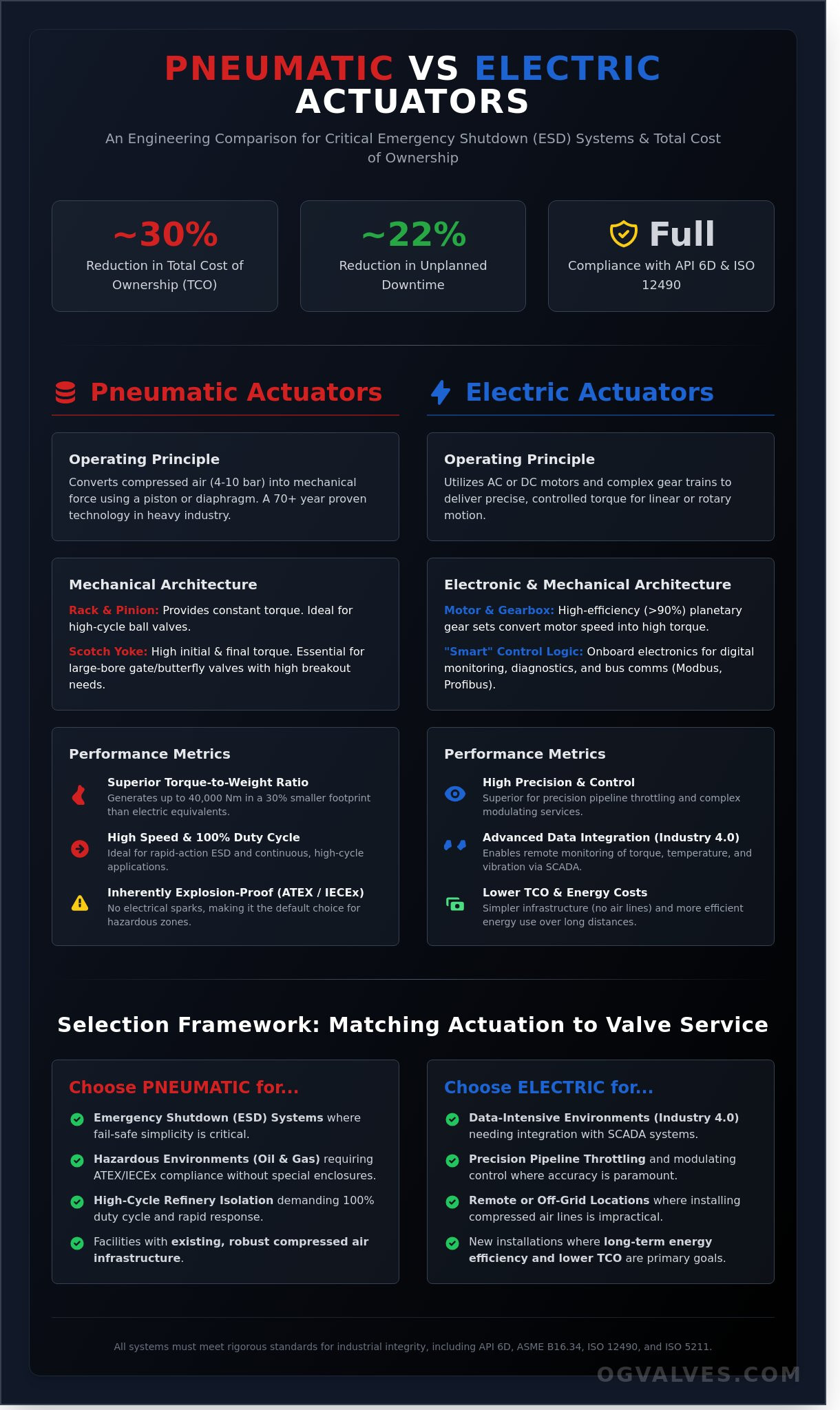
Can a 30% reduction in Total Cost of Ownership (TCO) coexist with the rigorous fail-safe requirements of an Emergency Shutdown (ESD) system? Most facility managers recognize that selecting between a pneumatic vs electric actuator isn’t merely a matter of preference but a critical decision affecting long-term infrastructure stability. You’ve likely managed the escalating maintenance demands of aging pneumatic lines that have surpassed their 12 year reliability threshold or faced the complex integration challenges of deploying electric units in remote, off-grid locations.
This technical analysis delivers an authoritative engineering comparison to ensure your valve systems meet API 6D and ISO 12490 standards without compromise. We’ll provide a clinical framework for selection by evaluating torque characteristics, duty cycle limitations, and fail-safe performance during critical power loss scenarios. You’ll gain the specific technical insights needed to eliminate uncertainty in Emergency Shutdown (ESD) protocols. This data allows you to optimize system performance, reduce unplanned downtime by 22%, and verify compliance across your entire global project portfolio.
Key Takeaways
Evaluate the fundamental mechanical advantages of pneumatic pistons versus electric gear trains to determine the most efficient torque delivery for specific valve specifications.
Navigate rigorous international compliance standards, including ATEX and IECEx, to ensure system integrity in explosive or corrosive industrial environments.
Assess the total cost of ownership (TCO) by auditing infrastructure requirements against long-term operational expenditure in the pneumatic vs electric actuator selection process.
Implement a clinical selection framework to match actuation technology with critical service requirements, ranging from high-cycle refinery isolation to precision pipeline throttling.
Fundamental Operating Principles: Pneumatic vs Electric Actuation
Industrial flow control relies on the conversion of potential energy into mechanical force. An actuator serves as the critical interface between the control system and the physical valve assembly. Pneumatic actuators function by converting compressed air energy into either linear or rotary motion. These systems typically operate within a pressure range of 4 to 10 bar (60 to 145 psi). The air pressure acts upon a piston or a flexible diaphragm to generate the necessary thrust. This method has dominated heavy industry for over 70 years. Its popularity remains high in oil and gas refineries because pneumatic components are inherently explosion-proof. They don’t produce electrical sparks, which ensures compliance with ATEX and IECEx standards for hazardous zones.
Electric actuators utilize single-phase or three-phase AC motors to drive a mechanical output. In some precision applications, 24V DC motors are specified for better speed control. Unlike pneumatic units that rely on fluid dynamics, electric models use complex gear trains to deliver precise torque. The choice between a pneumatic vs electric actuator often depends on the available infrastructure. Refineries with existing high-capacity air compressors favor pneumatics. Modern facilities are increasingly adopting “Smart” electric actuation to meet Industry 4.0 requirements. These units allow for digital plant monitoring and real-time diagnostic feedback, which reduces unplanned downtime by an estimated 25% in large-scale water treatment plants.
Pneumatic Architecture: Rack and Pinion vs Scotch Yoke
Pneumatic designs are categorized by their internal mechanical conversion. Rack and pinion actuators are the standard for compact, high-cycle ball valve service. They utilize a pair of pistons with integrated racks that turn a central pinion gear. This setup provides a constant torque output throughout the full 90-degree rotation. For large-bore gate or butterfly valves, engineers specify scotch yoke mechanisms. The scotch yoke design generates a torque curve that is highest at the beginning and end of the stroke. This is essential for overcoming high breakout torque requirements in valves that remain closed for extended periods. Control loops in these systems are managed by a solenoid valve for on/off service or a 4-20mA positioner for precise modulating control. All OG VALVES LTD. pneumatic systems adhere to ISO 5211 mounting standards to ensure global compatibility.
Electric Architecture: Motor, Gearbox, and Control Logic
Electric architecture is defined by the integration of the motor, the gear reduction unit, and the control logic. Multi-turn electric actuators are required for rising stem gate valves, while part-turn units handle 90-degree rotation for ball and butterfly valves. The gear train is the most critical mechanical component. It allows a high-speed, low-torque motor to achieve the massive torque required to seat a high-pressure valve. Efficiency in these gearboxes often exceeds 90% when using planetary gear sets. Modern electric units incorporate onboard electronics that support various bus communications, including Modbus, Profibus, and Foundation Fieldbus. This connectivity allows operators to monitor motor temperature, torque profiles, and vibration levels remotely. When evaluating a pneumatic vs electric actuator for a new installation, the ability to integrate into a centralized SCADA system often makes electric models the superior choice for data-intensive environments.
Pneumatic: High speed, fail-safe simplicity, and explosion safety.
Electric: High precision, easy data integration, and lower energy costs over long distances.
Compliance: Both systems must meet rigorous API 6D and ASME B16.34 standards for industrial integrity.
Performance Metrics: Torque, Speed, and Control Precision
Technical evaluation of a pneumatic vs electric actuator requires analyzing force density and operational endurance. Pneumatic actuators maintain a distinct advantage in torque-to-weight ratios. A standard rack-and-pinion unit can generate 40,000 Nm of torque within a footprint 30% smaller than an equivalent electric motor. This high force density makes them the primary choice for emergency shutdown (ESD) valves where rapid, high-torque seating is non-negotiable. When assessing performance metrics, engineers must account for the 100% duty cycle inherent to pneumatic designs. Unlike electric motors that require thermal protection and cooling intervals to prevent winding failure, pneumatic systems operate continuously without heat accumulation.
Electric units often operate on a limited duty cycle, frequently rated for S2 or S4 service classes per IEC 60034-1. If a process requires 1,200 cycles per hour, standard electric motors risk tripping thermal overloads. Pneumatic stroke speeds are significantly higher. A 100mm bore cylinder can achieve full closure in under 0.8 seconds. Electric actuators provide a controlled, linear speed profile, typically requiring 15 to 60 seconds for the same stroke depending on the gear ratio. This slower movement is vital for preventing hydraulic shock in liquid transport lines.
Torque Characteristics and Safety Factors
Sizing requires a rigorous analysis of three distinct phases. “Break Torque” is the force needed to unseat the valve from its closed position. “Run Torque” covers the dynamic friction during travel. “Seating Torque” is the final force required to achieve an ISO 5208 Leakage Rate A seal. Pneumatic output is directly proportional to supply pressure. A drop from 5.5 bar to 4.5 bar reduces output torque by approximately 18%, potentially stalling the valve. Torque safety factor is the ratio of actuator output to required valve torque. For critical oil and gas services, OG Valves recommends a 1.25 to 1.5 safety factor to ensure integrity under adverse conditions. Applying a precise valve actuator sizing methodology is essential to accurately calculate these safety factors and avoid costly torque miscalculations. You can review our technical torque charts for precise sizing data.
Modulation and Precision Control
Electric actuators excel in modulating services, offering positioning resolution as fine as 0.1% of the total span. Digital electric positioners eliminate the hysteresis and deadband often found in pneumatic bellows or diaphragm systems. Variable speed drives (VSD) in electric units allow for programmable ramp-up and ramp-down protocols. This mitigates the risk of water hammer in large-diameter piping systems. For chemical injection systems requiring precise flow adjustment, the rigidity of an electric gear train provides superior stability compared to the inherent compressibility of air in pneumatic cylinders. This ensures that the valve disc remains at the exact setpoint regardless of flow velocity fluctuations. Selecting a pneumatic vs electric actuator for these applications depends on whether the priority is speed or micro-adjustment accuracy.
Environmental Compliance and Safety Protocols
Selecting between a pneumatic vs electric actuator requires a rigorous assessment of site-specific environmental hazards. Industrial facilities operating in offshore or petrochemical sectors must adhere to ATEX Directive 2014/34/EU or IECEx standards to mitigate ignition risks. Pneumatic systems are traditionally favored in these volatile zones because they operate on compressed air rather than internal electrical currents. This inherent characteristic simplifies compliance in Zone 0 environments where explosive gases are constantly present. Electric units designed for these areas require heavy, explosion-proof housings rated for NEMA 7 or 9 to contain any internal blast, significantly increasing the unit’s footprint and weight.
The most common objection to electric actuation involves perceived vulnerability in wet or corrosive environments. Engineers often cite moisture ingress as a primary failure point. However, modern electric actuators utilize IP68 enclosures, which are tested for submersion at depths of 7 meters for 72 hours. To combat the high-salt content of coastal regions, these housings often feature epoxy coatings compliant with ISO 12944 C5-M standards. Pneumatic actuators aren’t immune to environmental degradation. Salt air leads to internal cylinder pitting if the instrument air isn’t meticulously dried and filtered to ISO 8573-1 Class 2 standards. Precision is vital here.
Temperature extremes dictate seal and component longevity. Standard pneumatic FKM seals maintain integrity between -29°C and +80°C. For cryogenic service reaching -50°C, specialized fluorosilicone seals are necessary to prevent brittle failure. Electric actuators face different constraints. High ambient temperatures combined with high duty cycles lead to thermal motor trips. Most heavy-duty electric motors include Class F insulation, rated for 155°C, but sustained operation in desert environments requires active cooling or internal heaters to prevent condensation during night-time temperature drops.
Fail-Safe Mechanisms: Spring-Return vs Battery Backup
In critical infrastructure, the fail-safe requirement is a non-negotiable specification for Emergency Shutdown (ESD) valves. Mechanical spring-return pneumatic actuators provide a definitive safety advantage; the stored energy in the compressed spring ensures the valve reaches its fail position immediately upon loss of pilot air. This hardware-based reliability is why many refineries mandate pneumatic vs electric actuator solutions for SIL 3 (Safety Integrity Level) loops. Electric alternatives have advanced through supercapacitors and internal lithium-ion battery packs. These systems provide enough reserve power for a final stroke, though they require more frequent diagnostic testing to ensure the energy storage hasn’t degraded over time. For applications where extreme high-torque isolation is the primary concern, engineers should also evaluate hydraulic valve actuator technology, which delivers superior force density for the most demanding high-pressure emergency shutdown scenarios.
Hazardous Area Suitability
Technical distinctions between intrinsic safety and explosion-proof housings define the installation’s complexity. Intrinsic safety limits the electrical energy to levels insufficient to ignite a specific hazardous atmospheric mixture. This is common in low-power instrumentation but rare in heavy-duty electric motors. Consequently, electric actuators rely on “Ex d” flameproof enclosures. These housings must prevent the transmission of an internal explosion to the external atmosphere. A critical technical requirement involves sealing electric conduit entries with certified flameproof glands to prevent gas migration through the wiring network. Pneumatic systems avoid this complexity, as the medium itself is inert, though they still require spark-resistant materials for external moving parts in Zone 0 locations.
Total Cost of Ownership (TCO) and Infrastructure
Selecting between a pneumatic vs electric actuator demands a granular assessment of both capital expenditure (CAPEX) and ongoing operational expenditure (OPEX). Engineers must look beyond the individual unit price to the entire lifecycle cost. Pneumatic systems generally offer a lower purchase price per unit, but the infrastructure required to support them is substantial. In contrast, electric actuators represent a higher initial investment that’s often offset by superior energy efficiency and reduced maintenance overhead over a 10 year period. The decision hinges on whether the facility’s existing utility footprint can absorb the specific demands of the chosen technology.
The Cost of Compressed Air Infrastructure
Compressed air isn’t free. It’s an expensive utility that requires a dedicated mechanical room and constant monitoring. A standard pneumatic installation requires air compressors, refrigerated dryers, and high-precision filtration to meet ISO 8573-1 Class 2 standards for particles and oil content. Without these components, moisture enters the actuator casing, leading to internal corrosion and premature seal failure. Data from industrial energy audits indicates that nearly 30% of industrial compressed air is lost to leaks before it ever reaches the end-use point. This inefficiency creates a constant drain on the facility’s power budget. However, if a facility already maintains a robust air header with surplus capacity, the pneumatic option becomes the most fiscally responsible choice. The incremental cost of adding a single drop to an existing 90 PSI line is negligible compared to the cost of new electrical conduit runs.
Electrical Integration and Lifecycle Costs
Electric actuators excel in “power-on-demand” applications. They consume zero energy when stationary, unlike pneumatic systems that rely on compressors to maintain line pressure 24 hours a day. The primary cost driver for electric units is the initial wiring. Running 480V three-phase power or 24V DC signal cabling to remote valve stations in a large-scale refinery can be expensive. Despite this, the lifecycle benefits are quantifiable. Electric units provide critical diagnostic data through HART or Modbus protocols, allowing for predictive maintenance. This reduces unplanned downtime, which can cost a plant upwards of $15,000 per hour in lost production. A high-quality electric motor is rated for a service life of 15 years in moderate conditions; pneumatic piston assemblies often require seal kit replacements every 250,000 to 500,000 cycles to maintain pressure integrity. When evaluating a pneumatic vs electric actuator for high-cycle service, the labor costs associated with pneumatic seal replacement often exceed the higher purchase price of an electric unit within 36 months of operation.
Pneumatic CAPEX: Low unit cost, high infrastructure cost for new compressor plants.
Electric CAPEX: High unit cost, high initial wiring and cabling expenses.
Pneumatic OPEX: High energy loss due to 30% leakage rates; frequent seal maintenance.
Electric OPEX: High energy efficiency; advanced predictive diagnostics reduce repair time.
Properly weighing these financial factors ensures long-term system reliability and budget compliance. For detailed specifications on high-performance hardware, explore our range of industrial valve solutions designed for rigorous service.
Selection Framework: Matching Actuation to Valve Service
Selecting the optimal pneumatic vs electric actuator requires a rigorous analysis of the operating environment, duty cycle, and available infrastructure. Engineers must prioritize mechanical integrity and functional safety over initial procurement costs. The following cases illustrate the technical logic used to determine the appropriate actuation technology for critical industrial services.
Case 1: Hazardous Refinery Zones. In ATEX Zone 1 environments, pneumatic actuators are the standard for high-cycle isolation. They eliminate the ignition risk inherent in electrical components. These units often exceed 1,000,000 cycles before requiring seal replacement, providing a reliable solution for rapid-response isolation in volatile hydrocarbon processing.
Case 2: Remote Pipeline Throttling. For pipelines located kilometers from compressed air stations, electric actuators provide superior performance. These units utilize 4-20mA signals for precision throttling with positioning accuracy within +/- 0.5%. They integrate directly with existing SCADA systems via Modbus or Profibus protocols, removing the need for expensive pneumatic infrastructure.
Case 3: Large-Bore Water Infrastructure. Large-bore gate valves used in municipal water treatment, specifically those with diameters between 24 and 48 inches, require massive torque. Electric or electro-hydraulic actuators are preferred here to manage the high stem forces required to overcome differential pressure. These systems ensure compliance with relevant industry standards and engineering best practices while providing controlled opening speeds to prevent water hammer. For the most demanding high-pressure isolation requirements in this category, a hydraulic valve actuator offers the highest available force output with precise torque control and ISO 12490 compliant fail-safe performance.
Case 4: Offshore ESD Systems. Safety-critical Emergency Shutdown (ESD) valves on offshore platforms demand pneumatic spring-return actuators. These mechanical fail-safe systems ensure the valve reaches a closed position in under 2 seconds during a total power loss. This capability is essential for meeting SIL 3 functional safety requirements in high-pressure subsea tie-backs.
Integrating with OG Valves Inventory
OG Valves LTD. engineers pair high-performance butterfly valves with actuators tailored for the thermal stresses of power generation. We verify that every assembly meets the specific torque requirements of the application, accounting for a 25% safety factor to handle seat friction increases over time. Our technical team provides detailed sizing for ball valves in high-pressure gas service, ensuring the pneumatic vs electric actuator choice aligns with API 6D and NACE MR0175 standards.
Rigorous testing protocols define our automated valve packages. Every unit undergoes a Factory Acceptance Test (FAT) that includes hydrostatic pressure testing and cycle speed verification. We document every performance metric to ensure the final assembly maintains pressure integrity under maximum operating conditions. This clinical approach to testing guarantees that our valve-actuator packages perform as specified upon site installation.
Conclusion: The Engineering Decision Matrix
The final decision-making hierarchy follows a strict progression: Safety, Infrastructure, Precision, and finally, Cost. If the application requires a fail-safe mechanical return, pneumatic systems are usually the primary choice. If the process demands digital integration and variable speed control across a vast geographic area, electric systems provide the necessary technical edge. Professional consultation is vital to avoid undersizing, which leads to premature component failure and costly downtime.
Selecting the wrong actuation package can compromise the safety of an entire facility. It’s essential to verify material compatibility and torque requirements with a qualified specialist who understands the nuances of industrial flow control. Consult with OG Valves LTD. technical team for bespoke actuator specifications to ensure your project meets all international engineering standards.
Optimizing Actuation Selection for Critical Infrastructure
Selecting the correct actuation technology is a critical engineering decision that impacts long-term operational integrity. Pneumatic systems remain the industry standard for high-cycle, fail-safe operations where rapid stroke speeds under 1.5 seconds are required for emergency shutdown. Conversely, electric units provide the 0.1% control precision necessary for complex modulating services across large-scale water treatment or oil refineries. Determining the optimal configuration of pneumatic vs electric actuator systems requires a rigorous assessment of duty cycles, torque requirements, and available power infrastructure. Engineers who follow a structured valve actuator sizing process aligned with API 6D and ASME B16.34 standards can eliminate the guesswork that leads to premature component failure and costly unplanned shutdowns. It’s a process where technical data must override anecdotal preference.
OG Valves maintains an ISO 9001 and API 6D compliant inventory to support these technical demands. Our engineering team specializes in high-alloy materials, including Super Duplex and Inconel 625, ensuring performance in highly corrosive environments. We offer global fast-track delivery for urgent industrial outages, leveraging a supply chain designed to reduce standard lead times by 40% or more. Aligning hardware specifications with specific valve service parameters prevents premature component failure and ensures project safety. Request a Technical Quote for Actuated Valve Packages to secure high-performance solutions for your facility. We’re ready to help you achieve 100% compliance on your next project.
Frequently Asked Questions
Which is more reliable in extreme cold: pneumatic or electric actuators?
Pneumatic actuators demonstrate superior reliability in temperatures below -40°C, provided the compressed air supply meets ISO 8573-1 Class 1.2.1 moisture requirements. Electric units often require integrated 50-watt space heaters to prevent internal condensation and electronic failure in sub-zero environments. Failure to manage moisture in pneumatic lines leads to seal degradation; however, the mechanical simplicity of the piston design remains more resilient than complex electrical circuit boards in Arctic conditions.
Can electric actuators meet the same speed requirements as pneumatic ones?
Pneumatic actuators provide significantly higher cycle speeds, often achieving full stroke in under 1 second for a 2-inch valve. Electric actuators typically require 10 to 60 seconds to complete a 90-degree rotation due to the high gear reduction ratios needed for torque generation. While specialized high-speed electric motors exist, they don’t match the rapid kinetic energy discharge of a 100 psi compressed air system during emergency shutdown protocols.
What are the main advantages of using pneumatic actuators in hazardous areas?
Pneumatic actuators are inherently spark-free, making them the standard for ATEX Zone 0 and NEC Class I, Division 1 environments. Unlike electric models that require heavy, explosion-proof NEMA 7 enclosures to contain internal arcs, pneumatic systems utilize non-flammable compressed air. This eliminates the risk of ignition in the presence of volatile hydrocarbons. It’s a critical safety factor that reduces compliance costs by 25% compared to certifying complex electrical installations in refinery settings.
How does the maintenance of an electric actuator differ from a pneumatic one?
Maintenance for a pneumatic vs electric actuator focuses on different mechanical failure points. Pneumatic units require seal replacement and lubrication every 1,000,000 cycles, alongside regular inspection of Filter, Regulator, and Lubricator stations. Electric actuators are often sealed for life, requiring zero internal lubrication, but they demand rigorous testing of electronic positioning sensors and battery backup systems. A failed circuit board in an electric unit necessitates a full component swap; pneumatic repairs involve simple O-ring kits.
Is it possible to convert a manual valve to an actuated one in the field?
Conversion of a manual valve to an actuated one is possible in the field if the valve features an ISO 5211 mounting pad. Technicians must remove the handwheel and install a specific mounting bracket and drive coupler to bridge the valve stem and the actuator. This process typically takes a two-person crew approximately 45 minutes for valves up to 8 inches. You’ll need to verify the breakaway torque requirements to ensure the new actuator provides a 25% safety factor over the valve’s operating torque.
What is the “duty cycle” and why does it matter for electric actuators?
The duty cycle represents the percentage of time an electric actuator can operate within a given period without overheating the motor. An actuator with a 25% duty cycle, rated under IEC 60034-1, should only run for 15 minutes out of every hour. Exceeding this limit triggers thermal overload protection, which halts operations to prevent permanent winding damage. High-frequency modulating services require 100% duty cycle motors to maintain continuous 24-hour performance without thermal degradation.
Do pneumatic actuators require a constant power source?
Pneumatic actuators don’t require a constant connection to a running compressor if the system includes a localized air receiver tank. These pressure vessels store enough energy at 90 psi to facilitate 3 to 5 full valve cycles during a total power loss. This stored mechanical energy provides a reliable fail-safe mechanism, allowing the valve to return to a secure position via spring-return action. Electric systems require expensive Uninterruptible Power Supplies to achieve the same safety redundancy.
Which actuator type is better for modulating flow control?
Electric actuators offer superior precision for modulating flow control, providing positioning accuracy within 0.1% of the total stroke. They integrate directly with 4-20mA or 0-10V control signals without the hysteresis often found in air-based systems. While a pneumatic vs electric actuator comparison shows that pneumatic units can modulate using digital positioners, the electric motor’s ability to make minute, incremental adjustments makes it the preferred choice for high-accuracy chemical dosing and steam pressure regulation.
 Responsive Menu