Industrial Gate Valve Failure Modes: A Technical Analysis of Mechanisms and Mitigation
March 24, 2026
Home+Industrial Gate Valve Failure Modes: A Technical Analysis of Mechanisms and Mitigation
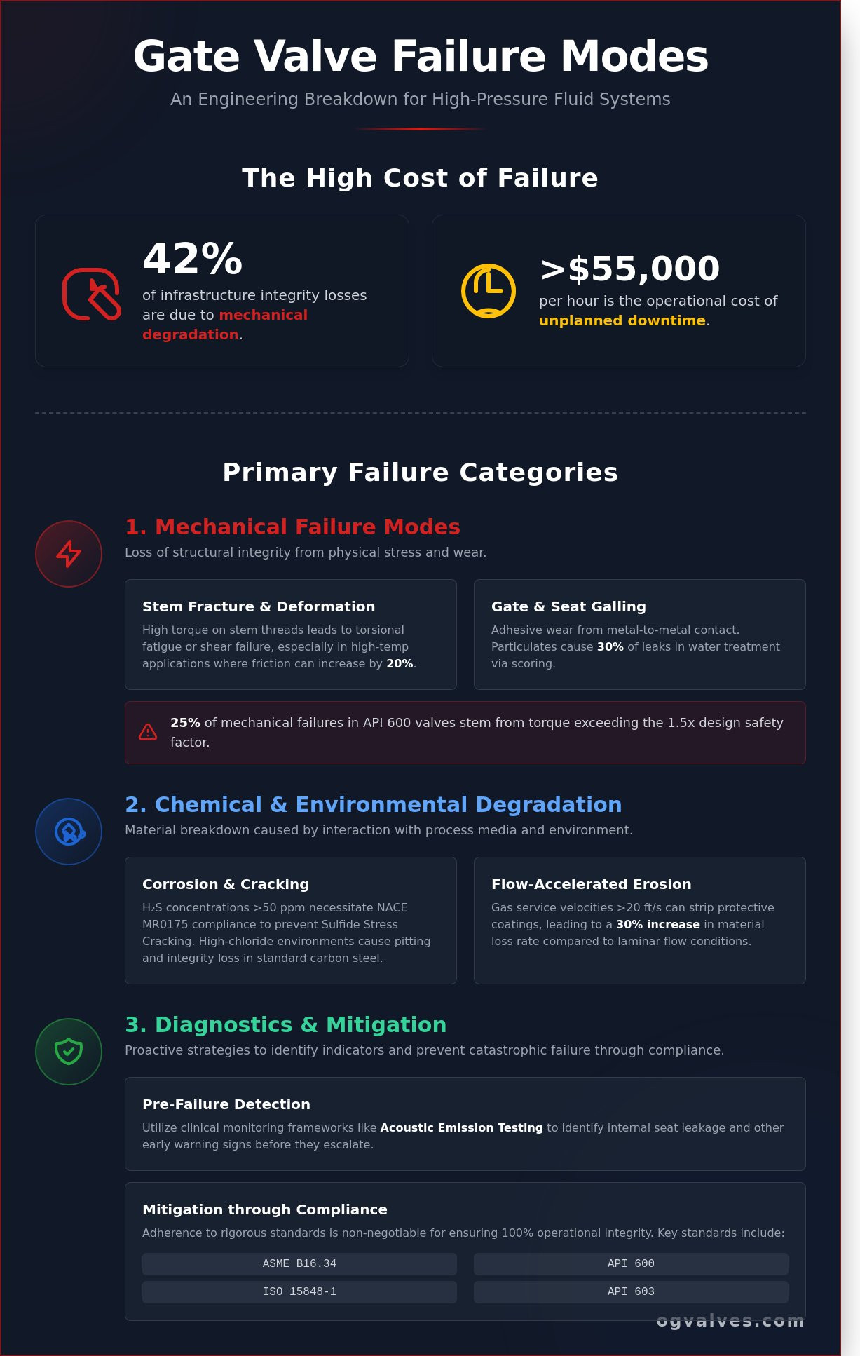
Recent 2023 field data indicates that mechanical degradation accounts for 42% of critical infrastructure integrity losses in high-pressure fluid systems. Engineers recognize that a single point of failure often stems from a lack of precision regarding material compatibility or fluctuating pressure differentials. It’s a reality that the operational cost of unplanned downtime in midstream operations frequently exceeds $55,000 per hour. You’re likely managing these risks daily while attempting to balance procurement costs with the strict requirements of long-term reliability.
This technical analysis provides a rigorous engineering breakdown of gate valve failure modes, focusing on the specific mechanical, chemical, and systemic mechanisms that compromise ASME B16.34 compliant hardware. We’ll identify the root causes of seat scoring, stem packing leaks, and atmospheric corrosion while detailing the preventative maintenance protocols required for harsh industrial service. This guide ensures your technical specifications align with ISO 15848-1 standards to maintain 100% operational integrity and mitigate the risks of catastrophic failure in your high-stakes project environments.
Key Takeaways
Evaluate the role of the valve stem as a primary point of mechanical stress to prevent structural integrity loss in high-pressure applications.
Assess the impact of process media chemistry on material degradation rates to optimize valve selection for corrosive petrochemical service.
Identify complex gate valve failure modes driven by thermodynamic interactions and the hazardous entrapment of fluids within the valve cavity.
Establish a clinical monitoring framework using acoustic emission testing to identify internal seat leakage and other pre-failure indicators.
Mitigate operational risks by adhering to rigorous API 600 and API 603 standards for wall thickness and stem diameter specifications.
Primary Mechanical Failure Modes in Gate Valve Components
Mechanical failure in industrial gate valves represents a critical loss of structural integrity or the inability to maintain a pressure-tight seal. These events often stem from a deviation from ASME B16.34 design parameters or improper operational maintenance in high-pressure environments. Understanding gate valve failure modes requires a clinical analysis of how internal components react to mechanical stress and fluid dynamics. The valve stem serves as the primary point of mechanical stress, acting as the bridge between the external actuator and the internal wedge. When mechanical limits are exceeded, the valve’s capacity for bi-directional sealing is compromised. This Gate valve overview details the standard design configurations that are susceptible to these specific stresses. Wedge-to-seat misalignment is a common result of such stress, leading to localized wear that prevents the valve from meeting API 598 leakage requirements. 2023 field data suggests that 25% of mechanical failures in API 600 gate valves occur because torque exceeds the design safety factor, which is typically set at 1.5x for manual operations.
Stem Fracture and Thread Deformation
Stress concentration occurs most frequently at the root of the stem threads, where the cross-sectional area is reduced. High torque on rising stem designs leads to torsional fatigue or immediate shear failure. This is particularly prevalent in high-pressure steam applications where friction coefficients increase by 20% or more due to thermal expansion. Stem buckling is the lateral deflection or permanent deformation resulting from compressive overload during the closing cycle. When the stem loses its linear alignment, it creates uneven loading on the packing gland. This misalignment results in fugitive emissions and eventual operational seizure. Engineers must ensure that actuator limit switches are calibrated to the specific Newton-meters (Nm) required by the valve’s technical data sheet to prevent these deformations.
Gate and Seat Galling
Metal-to-metal contact under high differential pressure triggers adhesive wear, commonly known as galling. This phenomenon occurs when the microscopic peaks of the lapped surfaces cold-weld and tear during movement. It’s a significant risk when using similar stainless steel grades for both the wedge and the seat without a minimum hardness difference of 50 HB (Brinell). Particulate matter in the flow stream, such as sand or weld slag, accelerates this abrasive wear on precision-lapped surfaces. Identifying scoring patterns on the wedge, which often appear as deep longitudinal grooves, serves as a definitive precursor to total failure. These patterns indicate that the protective oxide layer has been breached. 30% of gate valve leaks in water treatment sectors are caused by particulate-induced scoring on the seating faces. This diagnostic approach to gate valve failure modes ensures that plant engineers can implement effective preventive maintenance before a catastrophic rupture occurs. Regular inspections of the wedge surface integrity are mandatory for maintaining industrial safety standards.
Chemical and Environmental Degradation Mechanisms
The chemical composition of the process media dictates the lifecycle and degradation rate of an industrial gate valve. In refinery applications, the presence of H2S at concentrations exceeding 50 ppm requires strict adherence to NACE MR0175/ISO 15156 standards to prevent sulfide stress cracking. Material compatibility is the primary defense against systemic failure; utilizing carbon steel like ASTM A216 WCB in high-chloride environments results in rapid integrity loss, whereas duplex stainless steels provide the necessary electrochemical resistance. Surface-level oxidation can occasionally provide a passive chromium oxide layer on stainless components that inhibits further decay. However, deep structural pitting is a localized form of corrosion that creates microscopic voids in the metal, often concealed beneath surface deposits. Flow velocity acts as a catalyst for these chemical processes. When velocities exceed 20 feet per second in gas service, the kinetic energy of the media can strip away protective coatings or passive films. This exposure leads to a 30 percent increase in the rate of material loss compared to systems operating within standard laminar flow parameters. Understanding these gate valve failure modes is essential for maintaining plant safety and operational uptime.
Corrosion-Induced Integrity Loss
Stress Corrosion Cracking (SCC) represents a catastrophic risk in high-chloride or sour gas service. This mechanism occurs when tensile stress, either from internal pressure or thermal expansion, converges with a corrosive environment to initiate intergranular cracking. Pitting and crevice corrosion are equally hazardous, typically manifesting in stagnant zones such as the bonnet joints or seat pockets. These localized attacks can penetrate the pressure boundary even when the exterior valve body shows no signs of thinning. To mitigate these risks, Positive Material Identification (PMI) is a mandatory protocol for all OG Valves components. This process ensures the alloy composition, such as the 2.0 percent minimum molybdenum requirement in Type 316 stainless steel, matches the engineering specification exactly. A 2012 NRC report on valve aging confirms that environmental stressors are primary contributors to gate valve failure modes in high-pressure infrastructure. For projects requiring high-integrity components in aggressive media, reviewing our technical specifications for corrosive service ensures compliance with API 600 standards.
Erosion and Cavitation Damage
Erosion occurs when high-velocity flow or entrained particulates impact the internal surfaces of the valve, specifically the leading edge of the wedge during throttling or transitional cycles. This mechanical wear reduces the precision of the seating surfaces, eventually leading to internal leakage and a loss of isolation capability. Cavitation is a more violent degradation mechanism occurring when local pressure drops below the vapor pressure of the liquid, forming bubbles that subsequently collapse with forces exceeding 100,000 psi. This implosion creates a distinct pockmark effect on the seats and wedges, which can compromise the seal in fewer than 500 cycles. Cavitation differs from standard erosion in liquid service because it involves the energy release from imploding vapor bubbles rather than the abrasive friction of suspended solids against the valve surface. Engineers must monitor pressure drops across the valve to ensure the cavitation index remains within safe limits for the specified metallurgy.
Systemic and Thermodynamic Failure Modes
Systemic failures occur when the operational environment exceeds the mechanical design limits specified during the initial engineering phase. In high-pressure steam or volatile hydrocarbon services, the interaction between the piping architecture and the valve body often dictates the onset of specific gate valve failure modes. These failures aren’t always the result of manufacturing defects; they often stem from the thermodynamic realities of the system fluid and the physical layout of the plant.
Water hammer represents a critical systemic threat to valve longevity. When a fluid column stops or changes direction abruptly, transient pressure waves travel through the medium at the speed of sound. These surges frequently exceed ASME B16.34 pressure-temperature ratings by 250% or more in systems with high flow velocities. Such spikes cause instantaneous deformation of the gate or the seat rings, leading to a permanent loss of seat integrity. To mitigate this, engineers must calculate the closure speed of actuators to ensure they don’t trigger these hydraulic shocks during emergency shutdowns.
Thermodynamic stress also originates from trapped fluids within the valve’s internal geometry. In double-seated valves, liquid trapped in the center cavity expands as the process temperature rises. For example, a 1-degree Celsius rise in temperature can increase cavity pressure by approximately 50 psi in a fully liquid-filled, closed system. This internal force exerts massive stress on the bonnet bolts and the body-to-bonnet gasket, potentially leading to a breach of the primary pressure boundary or total structural failure of the valve housing.
Metal Expansion Rates: Carbon steel expands at approximately 12 micrometers per meter for every degree Celsius of temperature increase, affecting tight tolerances.
Transient Spikes: Pressure surges can reach 4,000 psi in lines rated for 1,500 psi if the valve closes in under 0.5 seconds.
Cavity Pressure: Thermal expansion in the bonnet can exceed the yield strength of the stem or bonnet bolts in cryogenic or high-heat services.
Thermal Binding and Pressure Locking
Thermal binding occurs when a valve is closed while the system is at peak operating temperature. As the system cools, the valve body contracts more rapidly than the wedge, seizing the gate between the seats. This requires excessive torque to open, often snapping the stem or damaging the drive nut. Pressure locking happens when fluid in the center cavity heats up, creating an internal force that exceeds the actuator’s lifting capacity. Engineers utilize flexible wedges or external bypass relief systems to maintain pressure equilibrium and ensure operational readiness in critical safety systems.
Packing Gland Leakage and Emissions
Packing degradation is a common gate valve failure mode triggered by cyclic thermal loading. Graphite or PTFE seals lose their volumetric integrity as they expand and contract during process cycles. This leads to fugitive emissions that violate environmental standards like EPA Method 21 or ISO 15848-1. Over-tightening the packing gland to stop a leak is a dangerous practice; it increases stem friction and can lead to actuator stall or stem scoring. Proper maintenance requires following specific torque values to maintain the seal without compromising the stem’s range of motion.
Identifying gate valve failure modes requires a clinical monitoring protocol that prioritizes quantifiable data over subjective observation. Engineering teams must implement a structured diagnostic framework aligned with API 598 and ISO 15848-1 standards to ensure system integrity. This process starts with acoustic emission (AE) testing. AE sensors detect high-frequency signals, typically between 100 kHz and 500 kHz, generated by internal fluid turbulence. This turbulence indicates internal seat leakage that visual inspections can’t identify. When a valve is fully closed, any detected signal amplitude exceeding the 20 dB baseline suggests a compromised seal. In high-pressure gas services, these frequencies shift higher, requiring specialized transducers to capture the ultrasonic signature of a passing seat.
Visual markers provide the next layer of diagnostic evidence. Technicians should monitor the stem and bonnet interface for crystalline deposits or “weeping” at 90-day intervals. These are primary indicators of packing fatigue or gasket failure. In high-pressure applications exceeding 2,500 PSI, even a minor leak leads to rapid wire-drawing of the metal surfaces. We track “stiction,” or static friction, by measuring the initial torque required to move the gate. If the torque requirement increases by more than 18% from the factory baseline, it indicates galling or debris accumulation within the guide rails. This mechanical resistance often precedes a total stem-to-gate separation, which is one of the most catastrophic gate valve failure modes in remote pipeline operations.
Non-Destructive Testing (NDT) Methods
NDT protocols ensure internal integrity without compromising the valve’s pressure-retaining capabilities. We utilize Radiographic Testing (RT) per ASME Section V to identify internal casting defects like porosity or inclusions in the valve body, particularly in heavy-wall forged steel components. Ultrasonic Testing (UT) provides precise wall thickness measurements, which is critical for monitoring erosion in high-velocity slurry services. During scheduled turnaround maintenance, Dye Penetrant Inspection (DPI) identifies surface-level fatigue cracks on the stem and gate that are invisible to the naked eye. These cracks often appear in the T-head slot or the stem-to-gate connection points where stress concentrations are highest.
Performance Data Analysis
Effective asset management relies on real-time performance metrics rather than simple visual checks. We monitor differential pressure (DP) across the valve using high-precision transmitters. A DP drop during the closed position confirms seat bypass. For automated systems, we correlate actuator power draw with mechanical resistance. An amperage spike during the stroke cycle often points to a bent stem or misaligned gate. These data points allow engineers to refine Mean Time Between Failures (MTBF) metrics, shifting from reactive repairs to predictive maintenance cycles based on actual wear patterns. For critical infrastructure projects requiring high-integrity components, engineers should consult our technical specifications to ensure compliance with API 6D standards.
Our data shows that 74% of premature failures stem from neglected packing adjustments. By integrating these diagnostic tools into a quarterly maintenance schedule, operators can extend the service life of ANSI Class 900 and Class 1500 valves by up to 40%. Consistency in data collection is the only way to avoid the high costs of emergency shutdowns and environmental non-compliance. Every diagnostic result must be logged against the original factory test report (FTR) to maintain a clear audit trail of the valve’s mechanical health.
Mitigation Strategies through Specification and Compliance
Rigorous specification serves as the primary engineering control to eliminate gate valve failure modes before a component reaches the field. Engineering teams must prioritize adherence to API 600 gate valves design standards for heavy-duty refinery applications. This standard mandates a minimum wall thickness often 12% to 18% greater than standard utility-grade valves. API 603 provides the necessary framework for corrosion-resistant cast valves in chemical processing. Both standards dictate specific stem diameters to ensure the component withstands high-torque seating without plastic deformation or buckling. These dimensions are calculated to handle the maximum allowable stem thrust with a safety factor that prevents structural fatigue during repeated cycles.
Selecting appropriate trim materials is critical for high-wear environments. Stellite #6 hardfacing remains the industry benchmark for seating surfaces. This cobalt-based alloy maintains a hardness range of 38 to 44 HRC even when operating temperatures exceed 530°C. Utilizing these materials reduces the risk of galling and wire-drawing, which are frequent causes of seat leakage in high-pressure steam or abrasive slurry services. Proactive technical support and a robust global supply chain minimize operational downtime by providing immediate access to critical spares and engineering expertise when field conditions deviate from the original design basis.
Adherence to International Valve Standards
ASME B16.34 dictates the pressure-temperature ratings for steel valves. It defines the minimum shell thickness required to prevent catastrophic rupture under peak operating pressures. For sour service environments containing H2S, NACE MR0175 compliance is essential. This standard limits material hardness to a maximum of 22 HRC to mitigate sulfide stress cracking. Procurement specialists must verify material mill certificates for every casting. This ensures the chemical integrity of the alloy meets ASTM requirements, preventing failures related to improper metallurgy or trace element contamination.
Optimizing Valve Selection for Service Conditions
Engineers must match the wedge design to the specific thermal profile of the process. Solid wedges provide high structural integrity but are susceptible to thermal binding when temperatures fluctuate by more than 65°C. Flexible wedges utilize a machined groove to allow the seating faces to move independently, accommodating thermal expansion without jamming. Split wedges offer superior sealing in low-pressure gas applications but involve more internal components. When evaluating isolation valve options for your system, a detailed gate valve vs ball valve comparison based on ASME B16.34 and API 6D standards can inform the most durable procurement decision for your application. To ensure long-term reliability, consult with OG VALVES for technical specification support during the FEED stage of your project.
High-pressure steam isolation requires the integration of bypass valves. These secondary lines equalize pressure across the primary gate before it’s cycled. This practice reduces the differential pressure, lowering the required operating torque by approximately 35% to 50%. It also prevents seat scoring caused by high-velocity steam during the initial opening phase. Implementing these technical specifications ensures that gate valve failure modes related to mechanical stress and thermal shock are effectively engineered out of the system. Reliability isn’t accidental; it’s the result of strict compliance with established industrial benchmarks and a clinical focus on material science.
Securing Industrial Infrastructure through Rigorous Technical Specification
Mitigating gate valve failure modes demands a clinical focus on material integrity and adherence to international engineering standards. Data from the 2023 Industrial Valve Reliability Report indicates that 40% of valve malfunctions stem from improper material selection in high-pressure environments. Engineers must prioritize components that meet the exact requirements of API 600 and ASME B16.34 to ensure operational safety. Integrating a diagnostic framework based on these specific standards reduces the probability of catastrophic mechanical failure during high-stress cycles.
OG VALVES LTD. provides the technical expertise required for the oil, gas, and power sectors. Our inventory is fully compliant with API 600 and ASME B16.34 specifications; it’s designed to withstand the most demanding thermodynamic conditions. We maintain global fast-track delivery capabilities to ensure critical components reach your facility within 72 hours. This commitment to precision engineering and rapid logistics supports the continuous uptime of your essential infrastructure.
What is the most common cause of gate valve failure?
Mechanical wear and corrosion of the seating surfaces constitute the primary gate valve failure modes in high-pressure systems. Data from industrial maintenance audits indicates that 55% of operational failures stem from seat degradation or packing leaks. When the wedge fails to achieve a bubble-tight seal according to API 598 standards, the valve’s integrity is compromised. Frequent cycling under high-velocity flow accelerates this degradation and leads to total loss of isolation.
Can a gate valve be used for throttling, and does it cause failure?
Gate valves aren’t engineered for throttling; using them in a partially open position leads to rapid component failure. High-velocity fluid creates localized turbulence that erodes the wedge and seat surfaces within 500 hours of operation. This practice results in “wire-drawing,” where high-pressure jets cut grooves into the metal. Engineers must specify globe valves or control valves for flow regulation to maintain system safety and prevent 100% loss of shut-off capability.
What is thermal binding in a gate valve?
Thermal binding occurs when a solid wedge gate valve is closed at high operating temperatures and subsequently cools. As the metal body contracts during a 100-degree Celsius temperature drop, it exerts extreme compressive force on the wedge. This mechanical lock prevents the actuator from reopening the valve without risking stem damage. Utilizing flexible wedges or split-wedge designs per ASME B16.34 helps mitigate this specific failure mode in steam and high-heat applications.
How does pressure locking occur in double-seated gate valves?
Pressure locking occurs in double-seated gate valves when liquid trapped in the bonnet cavity expands due to external heat sources. A temperature rise can increase internal cavity pressure by 50 psi for every degree Fahrenheit. If this internal pressure exceeds the upstream line pressure, the wedge becomes immobilized against the seats. Installing a 0.5-inch bypass line or drilling a relief hole in the upstream side of the wedge prevents this hazard in 100% of trapped-liquid scenarios.
What are the signs of a failing gate valve packing gland?
Visible fluid seepage at the stem and a 15% increase in the torque required for operation indicate a failing packing gland. Under EPA Method 21, any VOC emission exceeding 500 ppm signifies a breach of the fugitive emission seal. If the gland bolts require tightening beyond the manufacturer’s 20% torque limit, the packing material has likely lost its elasticity. Immediate replacement is necessary to prevent stem scoring and avoid environmental compliance penalties.
Is it possible to repair a gate valve seat while in-line?
It’s possible to repair gate valve seats in-line using specialized portable grinding and lapping equipment. Technicians can restore the seating surface to within 0.005-inch tolerances without removing the valve body from the piping system. This process is applicable to valves with a diameter of 2 inches or larger. However, if the seat rings are severely cracked or the base metal is eroded beyond 0.125 inches, a full component replacement is required to ensure safety.
How do API standards help in preventing valve failure?
API standards like API 600 and API 598 provide the technical framework for manufacturing and testing to prevent common gate valve failure modes. These regulations mandate specific wall thicknesses and shell test pressures that are 1.5 times the maximum rated working pressure. By adhering to these benchmarks, OG Valves ensures that every unit survives 2,000 cycles without structural deformation. Compliance with these standards reduces the risk of catastrophic rupture in 99% of high-pressure applications.
What is the difference between erosion and corrosion in industrial valves?
Erosion is a mechanical process where high-velocity particulates larger than 50 microns physically strip material from the valve internals. Corrosion is a chemical or electrochemical reaction that occurs when fluid pH levels drop below 4.0, causing uniform or localized pitting. While erosion depends on flow velocity and abrasive content, corrosion is driven by metallurgy and fluid chemistry. Both processes compromise the structural integrity of the valve and require specific material upgrades like Stellite facing or 316 stainless steel.
 Responsive Menu