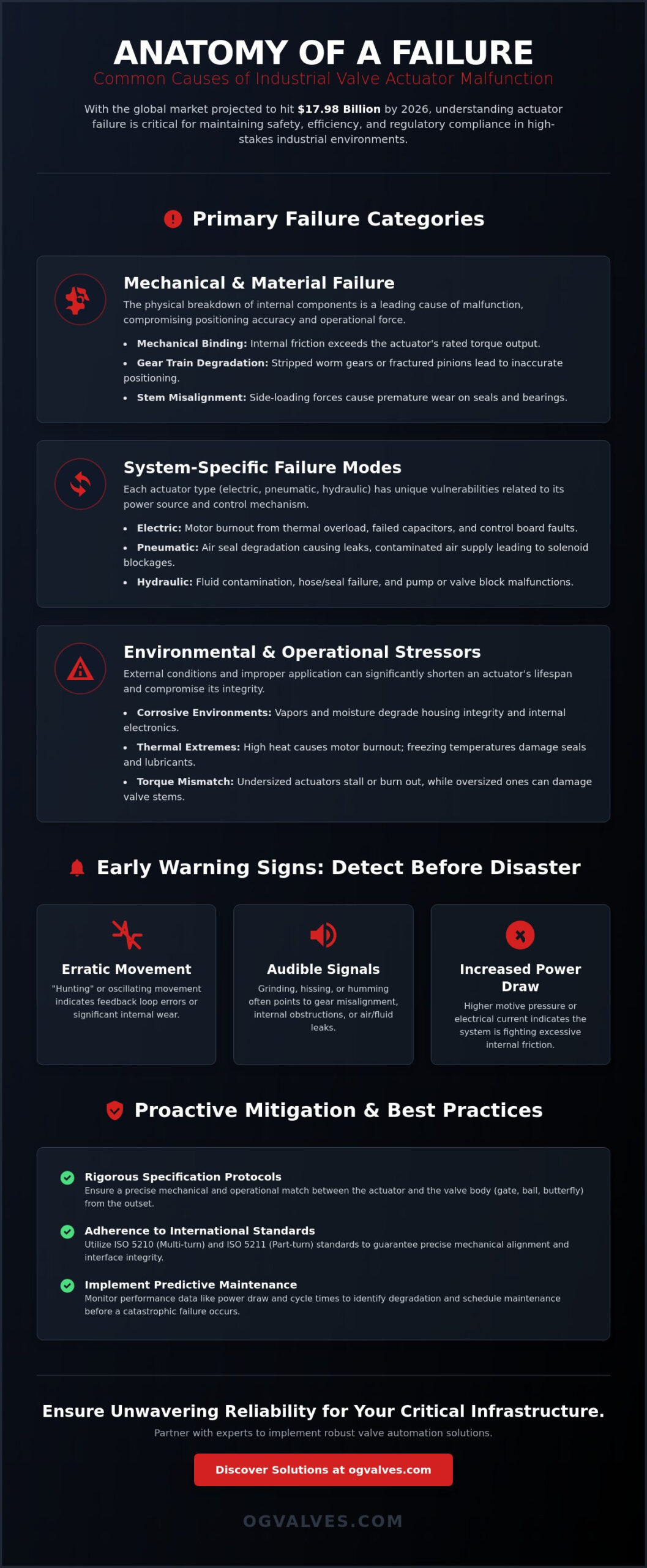
With the global valve actuators market reaching 17.98 billion USD in 2026, the industrial sector’s reliance on automated flow control has never been more critical or more prone to systemic risk. You’ve likely experienced the severe financial impact of unplanned downtime when a high-pressure gate or globe valve fails to cycle during a critical process. These malfunctions aren’t just isolated component breakdowns; they’re high-stakes safety risks that typically stem from complex, interlinked mechanical and electrical issues. Understanding the common reasons for valve actuator failure is the first step toward maintaining a reliable infrastructure that meets modern industrial benchmarks.
This technical analysis provides a comprehensive engineering breakdown of the mechanical, electrical, and environmental factors that compromise industrial actuator integrity. We’ll examine how the February 2026 updates to ISO 5210 and ISO 5211 regarding multi-turn and part-turn attachments dictate new standards for interface precision. You’ll gain a clear understanding of system-specific failure modes, ranging from pneumatic seal degradation to electric motor burnout. We conclude with a data-driven strategy for predictive maintenance and regulatory adherence to ensure your critical infrastructure operates with unwavering reliability.
Key Takeaways
- Identify how internal mechanical binding and gear train degradation compromise positioning accuracy in high-torque industrial systems.
- Analyze the common reasons for valve actuator failure across pneumatic, electric, and hydraulic configurations to prevent thermal overload and solenoid blockages.
- Evaluate the impact of external environmental stressors, such as corrosive vapors and thermal extremes, on housing integrity and seal longevity.
- Utilize rigorous specification protocols and international standards like ISO 5211 to ensure precise mechanical alignment between actuators and valve stems.
- Mitigate operational risks by aligning actuator performance ratings with the specific torque requirements of gate, ball, and butterfly valves.
Understanding the Criticality of Actuator Integrity in Industrial Systems
Industrial flow control relies on the seamless integration of valve bodies and their automated counterparts. An actuator is the mechanical link that translates electronic or pneumatic commands into physical force. When this link breaks, the entire process loop fails. Actuator failure is strictly defined as the inability to convert control signals into precise mechanical motion. This breakdown can manifest as an immediate operational stop, such as a seized motor, or as gradual performance degradation, where positioning accuracy drifts over time. Analyzing the common reasons for valve actuator failure requires a clinical look at both the mechanical interface and the electrical signal path. For a broader foundational context, this Valve actuator overview details the primary types of mechanisms used in these systems.
In high-output sectors like petrochemicals or power generation, the economic impact of a single failure is substantial. Unplanned downtime stops production and introduces safety risks that lead to regulatory scrutiny. The relationship between the valve body, whether it’s a high-pressure gate valve or a precise globe valve, and its actuator is one of total interdependence. If the actuator’s torque output doesn’t precisely match the valve’s breakout torque requirements, the system is fundamentally compromised. Reliability is a function of this unified system’s ability to maintain structural soundness under operational stress.
The Role of Actuators in Critical Infrastructure
Precision in emergency shutdown (ESD) applications is non-negotiable. These systems require actuators to move to a designated fail-safe position, such as fail-open, fail-close, or fail-last, during a power loss or signal interruption. Reliability here isn’t just about efficiency; it’s about facility safety and environmental compliance. A failure to cycle an ESD valve during an overpressure event can lead to catastrophic structural damage. Every component must adhere to global benchmarks to ensure the actuator survives the harsh conditions of a critical infrastructure environment.
Identifying the Early Warning Signs of Failure
Proactive maintenance depends on detecting subtle shifts in performance before a total stop occurs. Engineers must monitor for erratic movement, often called “hunting,” in modulating valves. This suggests a feedback loop error or internal wear. Audible signals like grinding, hissing, or humming often indicate gear misalignment or seal leaks. Additionally, an increased power draw or higher motive pressure requirements during standard cycles serve as quantifiable indicators that the system is struggling against internal friction. Identifying these common reasons for valve actuator failure early prevents the escalation of mechanical damage.
Primary Mechanical and Material Causes of Actuator Malfunction
Mechanical integrity is the foundation of reliable flow control. One of the common reasons for valve actuator failure involves mechanical binding. This occurs when internal friction within the valve body or the actuator mechanism itself exceeds the unit’s rated torque output. For instance, if a large industrial gate valve develops scale buildup on the wedge, the resulting resistance can exceed the actuator’s capability. This leads to stalled motors or sheared pinions that halt production entirely. Mechanical binding isn’t just a nuisance; it’s a symptom of a system operating beyond its design parameters.
Gear train degradation represents another critical failure point. Stripped worm gears or fractured motor pinions directly compromise positioning accuracy, making precise flow modulation impossible. This mechanical breakdown is often documented in rigorous testing environments; for example, a NASA analysis of actuator failures highlights how linkage wear and component overtravel can lead to catastrophic damage in high-stress applications. When these internal components fail, the actuator can no longer maintain the valve’s set point, resulting in process instability.
Stem misalignment introduces side-loading forces that are detrimental to system longevity. These lateral loads cause premature seal wear and can eventually lead to mechanical lock-up. When pressure integrity is lost due to seal and gasket failure, it’s often the result of chemical incompatibility between the process fluid and the elastomer material. This degradation remains a persistent issue in harsh chemical processing plants where seal hardening leads to motive fluid leakage.
Torque and Thrust Misalignment
Many engineers rely on a standard 10% safety margin when sizing actuators. In high-pressure applications, this is often insufficient. Breakaway torque requirements in aging systems increase significantly due to seat degradation and packing friction. Torque misalignment acts as the primary catalyst for internal gear fracture. If the actuator’s maximum torque isn’t carefully calibrated against the valve’s running torque requirements, the structural integrity of the drive nut is at risk.
Material Fatigue and Component Wear
High-cycle duty cycles put immense strain on spring return units and piston guides. Over time, metallurgical flaws in drive nuts or drive bushings manifest as catastrophic mechanical failure. Lubrication breakdown is a silent contributor here. As the lubricant loses viscosity or becomes contaminated, the coefficient of friction within the gear housing increases. This thermal and mechanical load accelerates the wear of critical load-bearing surfaces, which is among the most common reasons for valve actuator failure in continuous process environments.
System-Specific Failure Modes: Pneumatic, Electric, and Hydraulic
While mechanical binding and stem misalignment are universal stressors, the power source of an automated system introduces distinct vulnerabilities. Effective diagnostic protocols require an understanding of how different energy mediums—compressed air, electricity, or pressurized fluid—interact with internal components. In 2025, pneumatic actuators held a 37.63% revenue share of the global market, yet they remain highly susceptible to air quality fluctuations. Identifying these common reasons for valve actuator failure allows maintenance teams to transition from reactive repairs to predictive reliability. For a comprehensive comparison of these technologies, refer to this Industrial Valve Actuators: A Technical Guide to Automation and Control.
Pneumatic and Gas-Operated Vulnerabilities
Pneumatic systems rely on a consistent, clean air supply to maintain operational output. Contamination from moisture or oil carryover leads to internal cylinder corrosion and seal degradation. When condensation accumulates within the housing, it causes pitting on the cylinder walls, which increases friction and eventually leads to bypass leakage. Furthermore, a drop in standard cubic feet per minute (SCFM) results in inconsistent valve travel. This pressure instability often manifests as sluggish response times in high-performance butterfly valves, where precise positioning is required for process control. In gas-over-oil systems, orientation is a critical factor; improper mounting can lead to gas migration into the oil reservoir, compromising the hydraulic dampening effect.
Electrical and Electronic Breakdown
Electric motor-operated valves (MOV) face unique challenges related to thermal management and signal integrity. Thermal overload engagement is a frequent occurrence when the duty cycle of the motor is exceeded, often due to high-frequency modulating service. If the control voltage is incorrect or if wiring is exposed to corrosive atmospheres, the resulting electrical resistance can lead to fused contactors or blown internal fuses.
Limit switch drift is perhaps the most insidious of the common reasons for valve actuator failure in electric units. Mechanical vibration or thermal expansion can cause the limit switches to lose calibration. When this occurs, the actuator may attempt to drive the valve stem beyond its physical travel limit. For a globe valve or needle valve, this over-travel can result in a crushed seat or a bent stem, necessitating a full valve rebuild. Regular calibration against global benchmarks is the only way to ensure the electronic feedback matches the physical valve position.
Hydraulic actuators, while offering the highest power density for heavy-duty gate valves, are sensitive to fluid properties. Contamination from particulate matter can score the precision-honed surfaces of the piston, while aeration leads to “spongy” control and erratic movement. Temperature-induced viscosity changes also impact response times; as ambient heat increases, the fluid thins, potentially leading to internal bypass and a loss of holding torque.
Environmental Stressors and Operational Misalignment
Environmental factors are among the most pervasive common reasons for valve actuator failure in offshore and chemical processing facilities. While internal mechanical wear is often predictable, external stressors act as accelerators for systemic breakdown. Atmospheric corrosion from salt spray or caustic chemical vapors induces pitting and structural thinning of the actuator housing. If the protective coating is breached, the integrity of the pressure-retaining components is compromised. Engineers must also account for the ingress of particulate matter. Dust and grit clog breather vents and accumulate on exposed drive components, increasing the torque required for standard operation and leading to eventual motor stall.
Temperature extremes present a dual threat to automated systems. Ambient heat causes electronic component failure in electric units and leads to the hardening of elastomers in pneumatic and hydraulic seals. Once a seal loses its elasticity, it can no longer maintain a bubble-tight shutoff, resulting in motive fluid leakage. Vibration and harmonic resonance from adjacent high-pressure pumps also contribute to failure. Constant oscillation loosens critical fasteners and can disconnect internal wiring harnesses, leading to intermittent signal loss. Maintaining operational reliability requires selecting robust industrial ball and butterfly valves designed to withstand these rigorous site conditions.
Atmospheric and Chemical Exposure
Selecting the correct Ingress Protection (IP) and NEMA ratings is the primary defense against atmospheric degradation. In outdoor installations, UV radiation degrades non-metallic components like polycarbonate limit switch covers and external gaskets. For highly corrosive environments, the use of 316 stainless steel housings or specialized epoxy coatings is mandatory. These materials provide the necessary resistance to chemical vapors that would otherwise cause rapid oxidation of standard aluminum or cast iron enclosures.
Operational Errors and Maintenance Gaps
Human error during manual override procedures remains a significant risk factor. Improper handwheel declutching can strip internal drive gears or damage the engagement mechanism. Additionally, a “set and forget” mentality often leads to the seizure of rarely cycled valves. Without regular stroking, the valve stem can bond to the packing, creating a breakout torque that exceeds the actuator’s maximum rating. Positive Material Identification (PMI) testing prevents the use of incorrect alloys in actuator drive components, ensuring metallurgical compliance with project specifications. These maintenance gaps are common reasons for valve actuator failure that are entirely preventable through rigorous operational protocols.
Mitigating Failure Through Rigorous Specification and Selection
Preventing systemic breakdown requires a shift from reactive replacement to rigorous engineering specification. While previous sections detailed the mechanical and environmental common reasons for valve actuator failure, mitigation begins at the procurement phase. Adherence to updated standards, such as the February 2026 revisions to ISO 5210 and ISO 5211, is mandatory for ensuring interchangeability and proper alignment. The ISO 5211:2026 standard provides a global reference for flange dimensions and drive geometry for torques up to 1,000,000 Nm, while ISO 5210:2026 standardizes mechanical interface dimensions up to size F60. These benchmarks ensure that the interface between the actuator and the valve stem remains structurally sound under maximum load conditions.
Comprehensive project management is essential when integrating automated systems with heavy-duty gate or globe valves. It’s not enough to select a drive unit based on nominal torque alone. Engineers must evaluate the entire flow control loop, ensuring the actuator’s output profile matches the valve’s specific breakout, running, and seating requirements. This technical alignment eliminates the mechanical binding and gear train degradation that frequently lead to unplanned downtime. Leveraging technical expertise during selection ensures that material classifications, such as those verified through Positive Material Identification, are compatible with the intended process environment.
Engineering for Reliability: The OG VALVES Approach
Technical testing and strict quality assurance protocols are the only way to eliminate out-of-the-box failures. Every component undergoes verification against global benchmarks before dispatch to ensure operational output meets the design specification. This process confirms that the structural integrity of the drive nut and housing can withstand the high-cycle duty required in continuous process plants. For critical infrastructure replacements, fast-track delivery minimizes facility downtime, allowing for the rapid restoration of automated control. For detailed procurement frameworks and engineering standards, refer to Industrial Valves: The Engineer’s Comprehensive Guide to Selection and Standards (2026).
Next Steps for Facility Managers
A system-wide audit of actuator health and duty cycles is the first step toward long-term reliability. Managers should implement predictive maintenance schedules based on real-time diagnostic data and cycle counts rather than arbitrary calendar dates. This approach addresses the common reasons for valve actuator failure by identifying seal wear or limit switch drift before they cause a total stop. Consult with specialist suppliers to verify material certifications for high-stress applications, ensuring that every gate, ball, or butterfly valve in the system is paired with an appropriately rated drive unit. For professional assistance with high-specification infrastructure, Consult with OG VALVES LTD. for high-specification industrial actuators and valves.
Securing Critical Infrastructure through Engineering Excellence
Industrial systems in 2026 demand a clinical approach to component selection and maintenance. We’ve analyzed how mechanical binding, environmental stressors, and system-specific vulnerabilities like limit switch drift constitute the common reasons for valve actuator failure. Relying on outdated specifications or ignoring the updated ISO 5211:2026 standards introduces unnecessary risk to facility safety and output. True reliability is achieved when actuator torque profiles are precisely aligned with the mechanical requirements of gate, ball, or butterfly valves.
Implementing these rigorous standards ensures that your flow control loops maintain structural soundness under high-stress conditions. By focusing on material compatibility and predictive diagnostics, you can effectively eliminate the root causes of unplanned downtime. For organizations requiring industrial precision and dependable quality control, Contact OG VALVES LTD. for Technical Support and Global Valve Procurement. Our team leverages specialist technical expertise and rigorous testing protocols to support your heavy industry operations. We utilize global fast-track delivery capabilities to ensure your critical infrastructure remains operational and compliant with global benchmarks. Maintaining high-stakes trust through engineering excellence is the most effective path to long-term performance.
Frequently Asked Questions
What are the most common symptoms of a failing valve actuator?
The primary indicators of degradation include erratic movement, known as hunting in modulating service, and a measurable increase in power draw or motive pressure. You may also detect audible signals such as grinding, hissing, or humming, which suggest gear misalignment or seal failure. These symptoms often precede a total operational stop and indicate that the internal components no longer meet design specifications.
How does moisture in the air supply affect pneumatic actuators?
Moisture leads to internal cylinder corrosion and the rapid degradation of elastomer seals. When condensation accumulates, it causes pitting on the precision-honed cylinder walls, which increases friction and results in bypass leakage. This contamination eventually compromises the actuator’s ability to maintain the necessary thrust for high-pressure valve seating.
Can an undersized actuator damage the valve itself?
Yes, an undersized actuator can cause significant damage by failing to achieve a bubble-tight shutoff in gate or globe valves. This partial closure leads to high-velocity flow across the seating surfaces, causing erosion or wire-drawing. Additionally, repeated stalling under load puts excessive mechanical strain on the valve stem and drive nut, potentially leading to permanent deformation.
What is the expected lifespan of an industrial electric actuator?
Industrial electric actuators typically exceed 15 years of operational life when maintained within their specified duty cycles. This longevity depends on factors such as ambient temperature management and the integrity of the housing seals. In harsh chemical environments, the lifespan may be reduced if the unit isn’t rated for specific atmospheric corrosives.
Why does my actuator stop mid-stroke during operation?
Mid-stroke stops usually occur when the valve’s running torque exceeds the actuator’s output due to mechanical binding or scale buildup. Electrical issues, such as thermal overload engagement or limit switch drift, are also common reasons for valve actuator failure in these scenarios. Diagnostic data often reveals a spike in torque demand at the point of the stall.
How often should industrial valve actuators be cycled for maintenance?
Actuators should be cycled at least once every three to six months to prevent the valve stem from bonding to the packing. For critical emergency shutdown valves, partial-stroke testing is often performed more frequently to verify readiness without disrupting the process. Regular cycling ensures that lubricants remain distributed across the gear train surfaces.
What standards should I look for when specifying a new actuator?
You must ensure compliance with ISO 5210:2026 for multi-turn attachments and ISO 5211:2026 for part-turn interfaces. These updated 2026 standards define the mechanical dimensions and drive geometries required for precise alignment. Additionally, check for ISO 22109:2026 compliance if the system utilizes a gearbox for torque multiplication.
Is it possible to repair a stripped gear in an electric actuator?
While a stripped gear can be replaced, the repair must be performed with original equipment manufacturer parts to maintain the unit’s torque rating. In critical infrastructure, replacing the entire gear housing or the actuator assembly is often the preferred protocol to ensure safety. Using non-certified components can lead to catastrophic failure during high-torque operations.
 Responsive Menu