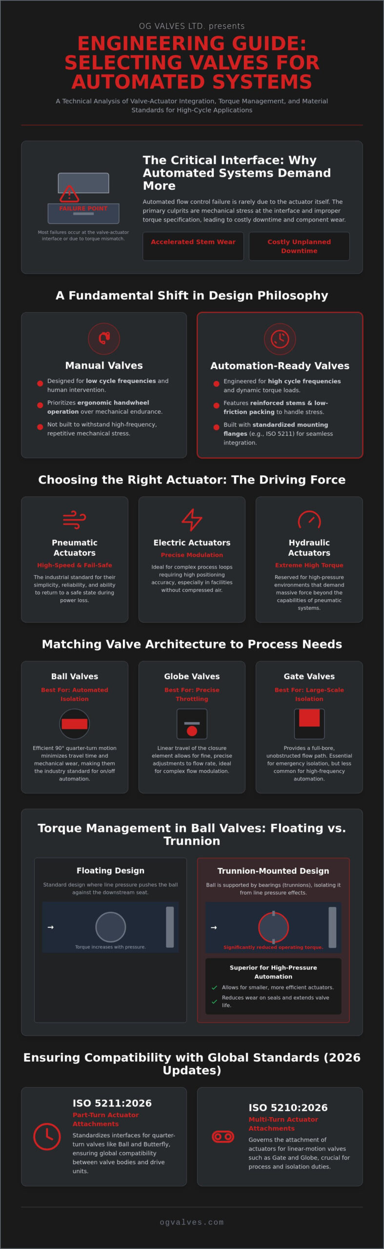
Mechanical failure in automated flow control is rarely a fault of the actuator; it’s almost always a failure of the valve-actuator interface or a fundamental mismatch in torque specification. Engineers understand that improper selection of valves for automated systems leads to accelerated stem wear and costly unplanned downtime. This clinical focus on the mechanical interface is necessary to ensure that gate, ball, or butterfly valves function within their designed safety margins under high-cycle conditions.
You’ve likely encountered the complications of material failure in corrosive environments or the inaccuracies of torque calculations that compromise seal integrity. This guide delivers a comprehensive engineering analysis of valve selection, actuator integration, and the material standards required for high-performance industrial applications. We’ll examine the updated 2026 standards, including ISO 5210:2026 for multi-turn attachments and ISO 5211:2026 for part-turn actuators, to provide a roadmap for achieving seamless integration and minimized maintenance through rigorous material precision.
- Identify the specific engineering requirements for valves for automated systems to manage dynamic torque and high cycle frequencies effectively.
- Evaluate the mechanical advantages of ball and butterfly valve designs for precise automated isolation and large-diameter flow control.
- Calculate critical torque parameters, including break-to-open and running torque, to ensure exact actuator sizing and prevent premature component wear.
- Implement rigorous material selection and Positive Material Identification (PMI) standards to maintain safety in high-pressure or corrosive industrial environments.
- Streamline procurement through global supply chain management to reduce lead times and ensure the availability of certified valve packages.
Industrial automation requires a fundamental shift in valve engineering. Manual operation relies on human intervention and low-frequency cycles. In contrast, valves for automated systems must interface directly with pneumatic, electric, or hydraulic actuators to facilitate remote process control. This transition demands a clinical focus on mechanical durability and adherence to global benchmarks to ensure long-term operational output. Engineering teams must evaluate the specific torque profiles required to overcome static friction and maintain consistent flow regulation.
The primary technical challenge involves managing dynamic torque and increased cycle frequency. Automated systems often operate at rates that would cause standard manual valves to fail. Fail-safe operation and real-time remote feedback are non-negotiable requirements in critical infrastructure. Standardization in this field is strictly governed by international protocols, such as ISO 5211 for part-turn valve actuator attachments, ensuring global compatibility between valve bodies and drive units.
The Role of Actuators in Valve Automation
Actuators serve as the mechanical drivers that convert energy into motion. A control valve package is only as reliable as its integration with these power sources. Selecting the correct drive mechanism depends on the environmental constraints and the required speed of response.
- Pneumatic actuators: These remain the industrial standard for high-speed, fail-safe applications. They’re valued for their simplicity and their ability to return to a safe state during power loss.
- Electric actuators: These units are ideal for precise modulation and facilities without compressed air infrastructure. They offer high positioning accuracy for complex process loops.
- Hydraulic actuators: These are reserved for extreme high-torque requirements in high-pressure environments where pneumatic systems lack the necessary force.
Manual vs. Automated Valve Design
Manual valve bodies prioritize ergonomic handwheel operation and are typically specified for low cycle frequencies. Automated variants require reinforced stems and low-friction packing to handle repetitive mechanical stress. Failure to account for these stresses leads to stem galling and packing leaks. An automation-ready valve is a valve body with a standardized mounting flange and high-cycle stem packing. By utilizing standardized interfaces, such as those defined in the 2026 updates to ISO 5210 and ISO 5211, engineers ensure that the valve and actuator operate as a singular, cohesive unit. This reduces the risk of mechanical mismatch and extends the mean time between failures (MTBF) for the entire assembly.
Selecting the correct mechanical architecture is the foundational step in ensuring the long-term reliability of valves for automated systems. While the actuator provides the necessary force, the internal valve design determines the torque profiles and the precision of the final control element. Ball valves represent the industry standard for automated isolation due to their efficient 90-degree operation. This quarter-turn motion minimizes travel time and mechanical wear compared to multi-turn designs. In contrast, globe valves remain the primary choice for precise automated throttling and flow modulation, as their linear travel allows for finer adjustments within the process loop.
The ISA96, Valve Actuator Committee establishes the framework for these mechanical interactions, ensuring that valve bodies are capable of withstanding the dynamic forces exerted by modern actuators. While gate valves are less common in high-frequency automation due to their extended travel times, they remain essential for large-scale emergency isolation where a full-bore, unobstructed flow path is required. Every selection must be anchored in the specific operational output and safety margins of the facility.
Automated Ball Valves: Floating vs. Trunnion Mounted
For engineers specifying automated packages, the distinction between floating and trunnion-mounted designs is a matter of torque management. Trunnion designs are superior for automation in high-pressure systems because the ball is supported by internal bearings, which significantly reduces the operating torque. This reduction allows for the use of smaller, more efficient actuators. Floating ball valves are cost-effective for smaller diameters, but they require higher actuator sizing; the ball is pushed against the downstream seat by process pressure, which increases friction. For detailed technical data on these configurations, refer to the Industrial Ball Valves guide.
High-Performance Butterfly Valves for Automation
Butterfly valves offer a compact, lightweight solution for large-diameter automated lines where space and weight are primary constraints. High-performance variants, specifically triple offset designs, provide the bubble-tight shut-off required in automated safety systems. These designs eliminate seat friction during the stroke, reducing torque and extending the service life of the automated assembly. Double offset butterfly valves balance cost and performance for general process automation where zero-leakage is not the absolute priority. You can consult the Butterfly Valve technical guide for application-specific torque data. If you require assistance with complex specifications, you can view our complete range of automation-ready valves to match your specific system requirements.

Precise actuator sizing determines the operational reliability of automated flow control. If the actuator is undersized, the valve will fail to cycle under full differential pressure. If it’s significantly oversized, the excessive force risks shearing the valve stem or damaging internal seating surfaces. For valves for automated systems, engineers must calculate three distinct torque values: break-to-open (BTO), which overcomes static friction; running torque (RUN), the force required during the stroke; and close-to-seat (CTS), which ensures a bubble-tight shut-off. These calculations are not static; they fluctuate based on line pressure, fluid viscosity, and ambient temperature.
Applying a safety factor is a mandatory protocol in industrial specification. Standard engineering practice dictates a buffer of 20% to 30% above the maximum measured torque. This margin accounts for unpredictable variables such as seat swelling, media buildup, or “dry” operation after extended periods of inactivity. Without this buffer, the automated package will likely stall during a process upset, exactly when reliability is most critical. Accurate sizing ensures the assembly functions within its designed safety margins throughout its service life.
Mechanical alignment is equally critical to prevent premature component failure. Mounting kits, consisting of brackets and couplers, must be machined to precise tolerances to ensure the actuator drive and valve stem are perfectly concentric. Misalignment causes stem side-loading, which accelerates packing wear and results in fugitive emissions. Every interface must be inspected for axial and radial precision to maintain the integrity of the pressure boundary and ensure smooth mechanical transmission.
Standardized Mounting: ISO 5211 Compliance
ISO 5211 defines the international standard for flange dimensions and drive square sizes for part-turn actuators. This regulation ensures that components from different global manufacturers remain interchangeable and safe. ISO 5211 compliance is the benchmark for modular automation systems. It allows procurement specialists to source valve bodies and actuators independently while guaranteeing a secure mechanical fit. This standardization simplifies inventory management and reduces the engineering complexity of large-scale infrastructure projects.
Control Accessories: Positioners and Limit Switches
Automation requires more than simple motion; it demands feedback and precision. Positioners act as the brain of the assembly, translating control signals, typically 4-20mA, into exact valve stem movement for throttling applications. For discrete isolation, limit switches provide remote confirmation of the valve’s status to the Distributed Control System (DCS). Solenoid valves serve as the interface between electrical logic and pneumatic power, controlling the air supply that drives the actuator. Each accessory must be rated for the specific hazardous area classification of the facility to ensure safety and regulatory adherence.
Metallurgical integrity is the first line of defense against systemic failure in automated flow control. High-performance valves for automated systems necessitate material specifications that exceed standard manual requirements. In corrosive industrial environments, such as offshore platforms or chemical processing plants, engineers must utilize high-spec materials like Super Duplex or Inconel. These alloys offer superior resistance to localized corrosion and mechanical fatigue, ensuring that the valve body remains intact under the high-frequency cycles typical of automated service. Selecting the correct alloy prevents premature degradation of the pressure boundary and extends the service life of the entire assembly.
Structural soundness is governed by a strict hierarchy of international benchmarks. API 600 defines the design requirements for heavy-walled steel gate valves used in refinery service, while API 6D provides the specification for pipeline and piping valves. For automated systems handling flammable media, fire-safe certification per API 607 is non-negotiable. This standard mandates that the valve must maintain its sealing integrity even when the primary soft seats are destroyed by high temperatures. Adherence to these standards guarantees that the valve assembly can withstand the dynamic loads and thermal stresses of the process environment without compromising safety.
The Role of PMI Testing in Automation Safety
Positive Material Identification (PMI) testing serves as a mandatory verification layer in the quality assurance process. It ensures the chemical composition of the valve body matches the provided mill test report (MTR), preventing the entry of non-compliant materials into the supply chain. This verification is particularly critical for automated valves; these components are often located in remote areas where manual inspection is difficult. OG VALVES LTD. prioritizes rigorous PMI testing to ensure that every component meets the exact alloy requirements of the project specification, maintaining long-term operational integrity in harsh conditions.
International Standards for Valve Automation
ASME B16.34 provides the technical framework for determining the pressure-temperature ratings of automated valve assemblies. This standard accounts for the material’s yield strength and the valve’s wall thickness to establish safe operating limits. Compliance with these codes allows for predictable performance across global supply chains. For engineers managing large-scale infrastructure, referencing the Comprehensive Guide to Industrial Valve Standards is essential for ensuring regulatory compliance across different jurisdictions. To ensure the long-term durability of your infrastructure, you can procure API-certified gate, ball, and butterfly valves directly from our technical specialists.
The transition from a technical specification to a physical installation requires a methodical approach to supply chain management. Project managers must ensure that the Bill of Materials (BOM) reflects the automation-ready status of the valve bodies, including the standardized mounting flanges and high-cycle packing discussed in previous sections. This prevents the procurement of manual-only variants that would require expensive field modifications. OG VALVES LTD. verifies every component against the engineering specification before dispatch, including the provision of comprehensive documentation packages that include Mill Test Reports (MTRs) and PMI verification data.
Fast-Track Supply for Heavy Industry
Maintaining an immediate stock of gate, ball, and butterfly valves is essential for rapid actuator integration and testing. This localized availability significantly reduces the standard lead time for high-spec automated packages, which is critical during planned facility shutdowns. Global logistics capabilities ensure that these components reach international sites on schedule, even in remote or hazardous regions. Strategic inventory management acts as a safeguard against supply chain volatility, providing the reliability that technical procurement specialists require for large-scale infrastructure. Every shipment is managed with a clinical focus on delivery timelines to prevent costly downtime and maintain the project’s critical path.
Technical Specification Support
Expert guidance during the procurement phase prevents a catastrophic mismatch between the valve body and the drive unit. Providing clear data on torque requirements and material compatibility ensures that the final assembly meets all operational output goals. Assistance with regulatory documentation and certification compliance, including API, ISO, and ASME standards, is a standard component of our project management protocol. This clinical approach to consulting eliminates ambiguity in the procurement process. To ensure your project meets its technical and temporal benchmarks, you can request a technical consultation or an industrial valve quote for your automation project. Our team focuses on functional reality and long-term performance to support your critical infrastructure needs.
Precision in valve automation is achieved through the technical synergy between the valve body and its actuator. Engineers must prioritize ISO 5211 compliance and rigorous material verification through PMI testing to maintain system integrity across high-cycle process loops. Precise torque management ensures that valves for automated systems operate within specific safety margins, effectively preventing premature mechanical wear and unplanned system downtime. Achieving this level of reliability requires a partner that understands the functional realities of heavy industry and the cost of failure in critical infrastructure.
OG VALVES LTD. maintains an extensive global inventory of API-certified gate, ball, and butterfly valves, providing specialist technical expertise for high-pressure automation. Our fast-track delivery capabilities ensure that high-spec components reach international industrial facilities exactly when required, minimizing the impact of supply chain volatility. Proper specification today is the foundation of long-term operational output and safety across critical infrastructure projects. Request a Technical Specification Quote for Automated Valves to secure the industrial precision your facility demands. We look forward to supporting your next engineering requirement.
What is the difference between a manual valve and an automation-ready valve?
An automation-ready valve is distinguished by its integrated mounting flange and reinforced internal components. Unlike manual valves designed for ergonomic handwheel operation, these valves feature high-cycle stem packing and reinforced stems to withstand the repetitive mechanical stress of automated cycling. This specialized design ensures long-term operational output in high-performance valves for automated systems.
How do I calculate the required torque for a valve actuator?
Calculating actuator torque requires summing the break-to-open, running, and close-to-seat torque values provided by the valve manufacturer. These values must be determined at the maximum differential pressure of the process. Engineers should apply a safety factor of 20% to 30% to account for unpredictable variables such as seat swelling or media buildup over the service life of the valve.
Why is ISO 5211 compliance important for automated systems?
ISO 5211 compliance is vital because it standardizes the flange dimensions and drive square sizes for part-turn actuators. This international benchmark ensures that valve bodies and actuators from different global manufacturers are mechanically compatible. It eliminates the need for expensive custom mounting hardware and guarantees a secure, aligned connection for safe and predictable power transmission.
Can any industrial valve be retrofitted for automation?
Not every industrial valve is suitable for automation. While many manual valves can be retrofitted with custom brackets, they often lack the reinforced stems and low-friction packing required for high-frequency operation. Retrofitting a standard manual valve may lead to accelerated component wear or catastrophic stem failure under the higher torque loads exerted by a mechanical actuator.
What are the advantages of pneumatic actuators over electric ones?
Pneumatic actuators provide faster response times and inherent fail-safe functionality through spring-return mechanisms. They’re generally preferred in heavy industrial sectors for their durability in hazardous environments and lower mechanical complexity. Electric actuators are typically selected when precise modulation is required or when the facility lacks a dedicated compressed air infrastructure for the control system.
How does PMI testing improve the reliability of automated valves?
PMI testing improves reliability by verifying that the alloy composition of the valve body matches the project’s technical specifications. This non-destructive testing prevents the installation of incorrect materials that could lead to catastrophic failure in corrosive or high-pressure environments. It is a critical quality control protocol for valves for automated systems where material integrity is the primary safety concern.
What standards govern valves used in automated oil and gas pipelines?
Automated oil and gas pipelines are primarily governed by the API 6D specification, which defines the structural requirements for pipeline and piping valves. Additionally, API 607 provides the standards for fire-safe testing, ensuring the valve maintains its seal during a thermal event. ASME B16.34 is utilized to determine the appropriate pressure-temperature ratings for the specific material classifications used.
What is the role of a valve positioner in an automated system?
The valve positioner serves as the control interface that ensures the valve stem reaches the exact position commanded by the control signal. It continuously monitors the actual stem location and adjusts the actuator’s power supply to correct any deviations from the setpoint. This feedback loop is essential for precise flow throttling and maintaining process stability in complex automated control loops.
 Responsive Menu