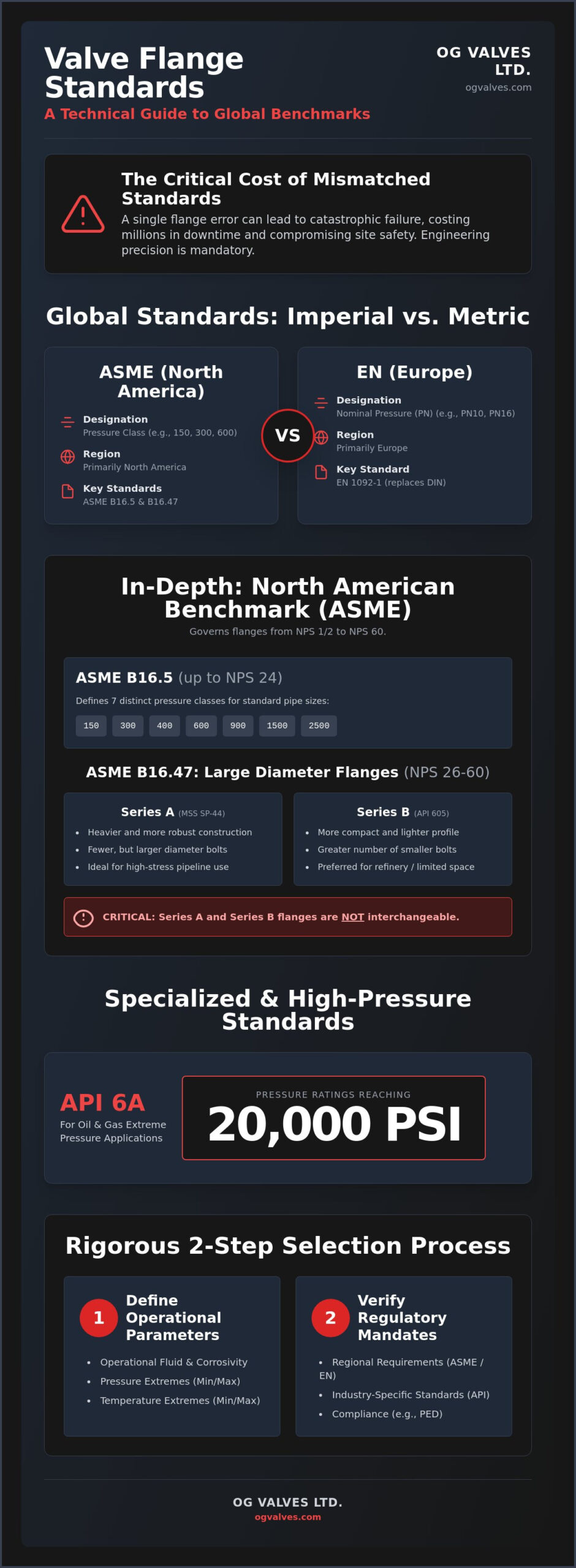
A single mismatched flange rating can lead to catastrophic pressure boundary failure, resulting in millions of dollars in operational downtime and compromised site safety. Engineering precision in high-stakes industrial applications isn’t optional; it’s a regulatory mandate. This valve flange standards guide provides the technical data required to eliminate procurement errors and ensure structural integrity across critical infrastructure projects.
You recognize that specifying the correct flange is a complex engineering task where there’s no margin for error. The persistent confusion between imperial ASME classes and metric EN PN ratings often causes significant delays in global supply chains. This technical reference delivers a clinical breakdown of current global benchmarks, including the mandatory requirements of ASME B16.5-2025 and the prevailing EN 1092-1:2018 standards. You’ll gain the precise data needed to navigate pressure-temperature ratings, material traceability, and compatibility requirements for gate, ball, and globe valves. We’ll examine the differences between Series A and Series B large-diameter flanges and provide the exact specifications required for regulatory compliance in 2026.
- Identify the critical engineering frameworks that prevent structural failure in high-pressure systems by defining precise bolt patterns and dimensional tolerances.
- Distinguish between the North American ASME B16.5 classes and the European EN 1092-1 PN ratings to avoid catastrophic component mismatches.
- Examine the specialized requirements for high-pressure oil and gas applications under API 6A, including pressure ratings reaching 20,000 psi.
- Utilize this valve flange standards guide to execute a rigorous two-step selection process based on operational fluid, temperature extremes, and regional regulatory mandates.
- Ensure full regulatory compliance for 2026 projects by understanding the transition from legacy DIN standards to unified international benchmarks.
Flange standards represent the rigorous technical frameworks that dictate every physical and metallurgical attribute of a piping connection. These protocols govern dimensions, bolt hole patterns, and pressure-temperature ratings, ensuring that components from disparate manufacturers interface without risk. Within this valve flange standards guide, it’s essential to recognize that standardization serves as the primary defense against fluid escape and structural collapse in high-pressure environments. When a system operates at several hundred bar, the mechanical integrity of the flange face and the precision of the bolt torque distribution are the only factors preventing a catastrophic release.
Primary governing bodies such as the American Society of Mechanical Engineers (ASME), the International Organization for Standardization (ISO), the European Committee for Standardization (CEN/EN), and the American Petroleum Institute (API) establish these benchmarks. While a technician might observe that two flanges appear identical to the naked eye, visual similarity doesn’t guarantee mechanical or metallurgical compatibility. For a comprehensive Flange standards overview, engineers should consult the specific annexes of these regulatory bodies to verify that bolt circle diameters and facing types align perfectly.
Pressure-Temperature Ratings and Material Synergy
Material selection fundamentally dictates a flange’s rated capacity. A Class 150 flange manufactured from carbon steel possesses a different pressure-handling profile than one forged from duplex stainless steel, especially as temperatures fluctuate. The ‘Rating’ or ‘Class’ isn’t a static value; it’s a variable that shifts based on the operational temperature of the media. As thermal energy increases, the allowable working pressure typically decreases to account for material softening and stress relaxation. Thermal expansion differentials between the flange, bolts, and gasket material can compromise the seal integrity if the components aren’t engineered with matching coefficients of expansion.
Regulatory Compliance in Heavy Industry
Adherence to international mandates like the Pressure Equipment Directive (PED) is a non-negotiable requirement for modern infrastructure. Validation of compliance relies heavily on Mill Test Reports (MTRs), which provide a documented audit trail of the material’s chemical composition and physical properties. In sectors like power generation, the selection of an incorrect standard impacts more than just immediate performance. It carries significant implications for insurance coverage and legal liability. Using this valve flange standards guide ensures that every Gate Valve or Check Valve specified meets the rigorous quality assurance protocols required to mitigate long-term operational risk.
ASME B16.5 serves as the foundational standard for flanged valves within the North American industrial sector, covering pipe sizes from NPS 1/2 through NPS 24. This valve flange standards guide classifies these components into seven distinct pressure classes: 150, 300, 400, 600, 900, 1500, and 2500. Each class defines specific pressure-temperature ratings that ensure mechanical stability under varied operational loads. The 2025 revision of this standard, which becomes mandatory on January 1, 2026, emphasizes enhanced material traceability and refined quality control metrics to support modern safety protocols. For systems exceeding NPS 24, engineers must pivot to ASME B16.47, which governs large-diameter valves up to NPS 60.
Specifying the correct ASME B16.47 flange requires a technical distinction between Series A and Series B configurations. Series A, derived from MSS SP-44, utilizes larger bolt diameters and fewer bolts compared to Series B. These flanges are typically heavier and more robust, making them suitable for high-stress pipeline applications. Conversely, Series B flanges, originating from API 605, feature a more compact profile with a higher quantity of smaller bolts. Series B is often preferred in refinery environments where space constraints are a factor, though it’s critical to note that Series A and Series B are not interchangeable. If you’re finalizing a procurement order, ensure your Gate Valve specification explicitly identifies the required series to prevent installation failure.
Specifying ASME Flange Faces
Selecting the appropriate flange face is a technical requirement based on the gasket material and operational pressure. The Raised Face (RF) is the most prevalent configuration, concentrating pressure on a smaller gasket area to increase seal effectiveness. In contrast, Flat Face (FF) flanges are utilized for cast iron or non-metallic valves to prevent cracking the flange when bolts are tightened. For high-pressure isolation in extreme environments, the Ring Type Joint (RTJ) remains the industry benchmark. RTJ flanges utilize a metallic ring gasket that fits into a machined groove, providing a metal-to-metal seal capable of withstanding severe thermal cycling. Surface finish also plays a vital role; serrated finishes provide the necessary grip for soft gaskets, while smooth finishes are reserved for specialized sealing requirements.
Bolting Patterns and Dimensional Tolerances
Interchangeability across global manufacturing chains relies on the standardized bolt hole circles and quantities defined by ASME. These tolerances ensure that a valve manufactured in one region will align perfectly with piping systems installed elsewhere. While ASME dominates North American projects, global procurement often requires knowledge of the EN 1092-1 European Framework to manage metric system integration. Maintaining strict adherence to the ASME 600 standards for gate valves is essential for ensuring that the valve body and flange interface function as a unified pressure vessel. Verifying these dimensional tolerances against certified Mill Test Reports is the only way to guarantee site safety in high-stakes infrastructure.

The transition from legacy German DIN 2501 standards to the unified EN 1092-1:2018 framework has streamlined European industrial procurement, yet it requires rigorous technical attention. This metric system utilizes the PN (Pression Nominale) designation to define pressure ratings, ranging from PN6 for low-pressure utilities to PN400 for extreme high-pressure applications. Unlike the American system, the PN rating directly correlates to the maximum allowable pressure in bar at a reference temperature of 20°C. This valve flange standards guide emphasizes that while many DIN standards are superseded, they remain prevalent in legacy infrastructure, necessitating a dual understanding of both systems for maintenance and replacement cycles.
Metric and imperial flanges are fundamentally non-interchangeable. The differences extend beyond unit conversion; bolt hole diameters, bolt circle pitches, and the quantity of fasteners vary significantly between EN and ASME benchmarks. For example, an EN 1092-1 flange utilizes M-series metric bolts, which won’t align with the UNC or UN threads used in ASME B16.5 systems. Attempting to force compatibility through specialized adapters or modified bolting is a high-risk practice that compromises the pressure boundary and voids manufacturer warranties. Precise alignment of the gasket seating surface is only possible when the governing standard matches the mating pipework exactly.
EN 1092-1 Flange Types (Type 01 to Type 37)
The EN 1092-1 standard categorizes flanges into specific “Types” based on their construction and attachment method. Type 01 (Plate) and Type 11 (Weld Neck) are common in general piping, but Type 21 (Integral) is the definitive requirement for most cast and forged valve bodies. Beyond the type, engineers must specify the “Form” of the flange face, labeled A through H. Form A represents a flat face, while Form B is the standard raised face. Specialized forms like Form C (Tongue) and Form D (Groove) are utilized for high-integrity seals where gasket blowout must be physically prevented by the flange machining.
ASME vs. EN: The Risk of Mismatched Ratings
A frequent error in international procurement involves the assumption of “rough equivalence” between PN ratings and ASME Classes. Engineers often compare PN16 to Class 150 or PN40 to Class 300, but these designations don’t share identical pressure-temperature curves. A PN16 rating indicates a 16-bar capacity at ambient temperature, whereas a Class 150 rating allows for approximately 19.6 bar under similar conditions. This discrepancy means that substituting a PN-rated valve into an ASME-designed system can lead to operating the component beyond its certified limit. Consult our Industrial Valve selection guides to ensure that your multi-standard system design accounts for these metallurgical and mechanical variances. Bolt alignment doesn’t equate to pressure compatibility; only a clinical review of the material’s yield strength and the standard’s specific rating table ensures operational safety.
In upstream oil and gas production, standard industrial benchmarks like ASME B16.5 are insufficient for the extreme pressures encountered at the wellhead. The API Specification 6A stands as the definitive regulatory framework for wellhead and christmas tree equipment, governing connections that must withstand pressures reaching 20,000 psi. This valve flange standards guide identifies API 6A as a safety-critical requirement for environments where thermal cycling and corrosive media are constant. While ISO 7005-1 attempts to harmonize international benchmarks by incorporating both ASME and EN designs, specialized sectors continue to rely on these distinct, high-performance interfaces to ensure zero-leakage integrity across the pressure boundary.
High-Pressure API 6A Specifications
API 6A flanges are categorized primarily into Type 6B and Type 6BX designs. Type 6B flanges are typically used for pressures up to 5,000 psi and utilize RX or R-type ring gaskets. Type 6BX flanges are reserved for higher pressure ratings, starting at 10,000 psi and extending to 20,000 psi, featuring a raised face that ensures the gasket is fully energized by the bolting force. These configurations rely on BX and RX metallic ring gaskets to create a metal-to-metal seal that is physically superior to standard soft gaskets. API 6A flanges are mandated for upstream high-pressure service because their design accommodates the extreme tensile and compressive stresses inherent in well-control operations. If your project involves Ball Valves or Gate Valves for subsea or wellhead applications, verifying API 6A compliance is a non-negotiable engineering step.
JIS Standards in Global Procurement
Japanese Industrial Standards (JIS) represent another technical layer of complexity in global valve procurement, particularly for projects based in or sourced from the Asia-Pacific region. JIS B 2220:2019 classifies flanges using a “K” rating system, such as 5K, 10K, 16K, and 20K. These ratings indicate the nominal pressure capacity and dictate specific bolt patterns that do not align with ASME or EN counterparts. Integrating a JIS-standard component into an ASME-governed system requires a clinical understanding of dimensional variances to avoid mechanical interference during assembly. Identification of these flanges relies on verifying the nominal pressure markers and measuring the bolt circle diameter against the JIS specification tables. OG Valves facilitates cross-standard procurement by sourcing certified components that meet these regional requirements while maintaining the structural soundness required for international facilities.
Executing a successful procurement strategy requires a methodical transition from theoretical benchmarks to site-specific engineering requirements. This valve flange standards guide provides the necessary framework to ensure that every connection maintains its pressure boundary under the most rigorous service conditions. Engineers must follow a structured four-step protocol to eliminate specification errors that lead to operational downtime or safety breaches.
- Step 1: Define the Operational Envelope. Identify the chemical properties of the fluid alongside the maximum pressure and temperature extremes. These parameters dictate the required pressure class and material grade.
- Step 2: Determine Governance. Establish whether the project falls under North American ASME, European EN, or regional JIS mandates. This selection must align with existing piping infrastructure to ensure dimensional compatibility.
- Step 3: Verify Metallurgical Compatibility. Evaluate the galvanic potential between the flange material and the mating pipe. Mismatched alloys, such as connecting carbon steel flanges to stainless steel piping without proper isolation, will trigger accelerated galvanic corrosion at the interface.
- Step 4: Configure the Seal. Select the flange face type (RF, FF, or RTJ) and a gasket material that possesses the required chemical resistance and thermal stability for the media.
Avoiding Common Procurement Errors
One of the most frequent technical errors in procurement is ‘Class-hopping,’ which involves specifying a higher-class flange for a valve body designed for a lower pressure rating. While this might appear to provide a higher safety factor, it often results in mechanical mismatch where bolt torque requirements for the flange exceed the structural tolerances of the valve body, leading to flange deformation or uneven gasket loading. Precision in bore diameter is also critical. A mismatch between the valve bore and the pipe internal diameter creates a physical step in the flow path, inducing turbulence that causes localized erosion and cavitation. When specifying wafer-style components, consult our Guide to Industrial Butterfly Valves to ensure proper alignment between the valve disc and the mating flange faces.
Quality Assurance and Testing Protocols
Final validation of any flanged valve relies on rigorous testing standards. Hydrostatic testing of the flanged connection, conducted per API 598 or ISO 5208, verifies the integrity of the casting and the seal under 1.5 times the rated working pressure. Positive Material Identification (PMI) is a non-negotiable step in the quality control process, ensuring that the flange metallurgy precisely matches the certified Mill Test Reports. OG VALVES LTD. utilizes these clinical validation protocols to verify every technical specification before dispatch, ensuring that components are ready for immediate integration into high-stakes infrastructure. This commitment to engineering excellence supports global fast-track delivery requirements without compromising the safety or durability of the installation.
Adhering to the rigorous frameworks established by ASME, EN, and API ensures that critical valve interfaces remain leak-free under extreme operational loads. This valve flange standards guide has detailed the necessity of clinical precision when navigating the transition from legacy DIN systems to the mandatory requirements of ASME B16.5-2025. Engineers must prioritize material synergy and exact dimensional alignment to mitigate the risk of catastrophic structural failure in high-pressure applications. Successful infrastructure projects depend on the unwavering reliability of these mechanical connections.
OG VALVES LTD. has operated as a specialist global supplier since 2014, maintaining deep technical expertise across ASME, API, and EN benchmarks. Our logistics framework is engineered for fast-track delivery to support critical infrastructure projects without compromising regulatory adherence or structural soundness. Request a Technical Quote for Standardized Industrial Valves to ensure your next procurement meets these exacting engineering standards. Achieving zero-leakage performance starts with a technically sound specification that accounts for every variable in the operational environment.
What is the difference between ASME B16.5 and B16.47?
ASME B16.5 is the standard for pipe flanges and flanged fittings ranging from NPS 1/2 through NPS 24. ASME B16.47 addresses large-diameter steel flanges from NPS 26 through NPS 60. While B16.5 is the universal benchmark for standard piping, B16.47 introduces Series A and Series B specifications to manage the increased mechanical stresses inherent in larger bores. These standards aren’t interchangeable and require specific bolting configurations to maintain pressure boundary integrity.
Can an ASME Class 150 flange be bolted to a PN16 flange?
You can’t bolt an ASME Class 150 flange directly to a PN16 flange without specialized adapters. Although they serve similar pressure roles, their bolt hole circles, bolt quantities, and physical dimensions differ significantly. Attempting to force a connection between imperial and metric systems compromises the structural soundness of the joint. This valve flange standards guide recommends using dedicated transition pieces to ensure regulatory compliance and prevent catastrophic fluid escape during operation.
What does the ‘PN’ in PN16 or PN40 stand for?
PN stands for Pression Nominale, which translates from French to Nominal Pressure. This metric rating system, utilized in EN 1092-1 and ISO standards, indicates the maximum allowable working pressure in bar at a reference temperature of 20°C. For instance, a PN40 flange is designed to withstand 40 bar at ambient conditions. As operational temperatures increase, the allowable pressure decreases based on the specific material’s yield strength and thermal expansion properties.
When should I use a Ring Type Joint (RTJ) flange over a Raised Face (RF) flange?
Use a Ring Type Joint (RTJ) flange for high-pressure and high-temperature applications where a metal-to-metal seal is required. RTJ flanges feature a machined groove for a metallic ring gasket, making them ideal for severe cyclic conditions. A Raised Face (RF) flange is suitable for general industrial service, as it concentrates bolting force onto a smaller gasket area to create an effective seal. RF designs are more common in standard process piping below Class 900.
How do I determine the pressure-temperature rating of a flange?
Determine the pressure-temperature rating by consulting the specific tables within the governing standard, such as ASME B16.5 Table 2. These ratings are dependent on the material’s metallurgical classification and the actual operating temperature of the media. As the temperature rises, the material’s mechanical strength diminishes, necessitating a reduction in the maximum allowable working pressure. You must cross-reference your specific material grade with the temperature-dependent values provided in the latest regulatory documentation.
Are DIN and EN 1092-1 flanges interchangeable?
EN 1092-1 flanges have largely superseded the older German DIN standards, but they’re often functionally interchangeable in many applications. Most dimensions for bolt circles and hole quantities remained consistent during the transition to the unified European framework. However, it’s critical to verify the specific “Type” and “Form” when replacing legacy DIN 2501 components. This valve flange standards guide advises a clinical review of the original equipment manufacturer’s drawings to confirm that the flange metallurgy and facing match.
What are the common materials used for industrial valve flanges?
Industrial valve flanges are primarily manufactured from carbon steel, such as ASTM A105, or various grades of stainless steel like 304L and 316L. High-performance applications may require alloy steels or duplex stainless steel to resist localized corrosion and high-stress environments. Material selection must align with the valve body’s metallurgy to prevent galvanic corrosion. Each material grade is assigned to a specific group within the standards, which ultimately dictates its pressure-temperature performance limits.
What is the importance of flange face surface finish?
The flange face surface finish is critical for ensuring the friction and seating required for a leak-free joint. Standard industrial flanges often utilize a serrated spiral or concentric finish to “bite” into soft gaskets, preventing blowout under pressure. Smooth finishes are typically reserved for metal-to-metal seals or specialized gaskets in high-vacuum applications. Maintaining the specified Ra (Roughness Average) value prevents fluid migration across the flange face and ensures the long-term reliability of the pressure boundary.
 Responsive Menu