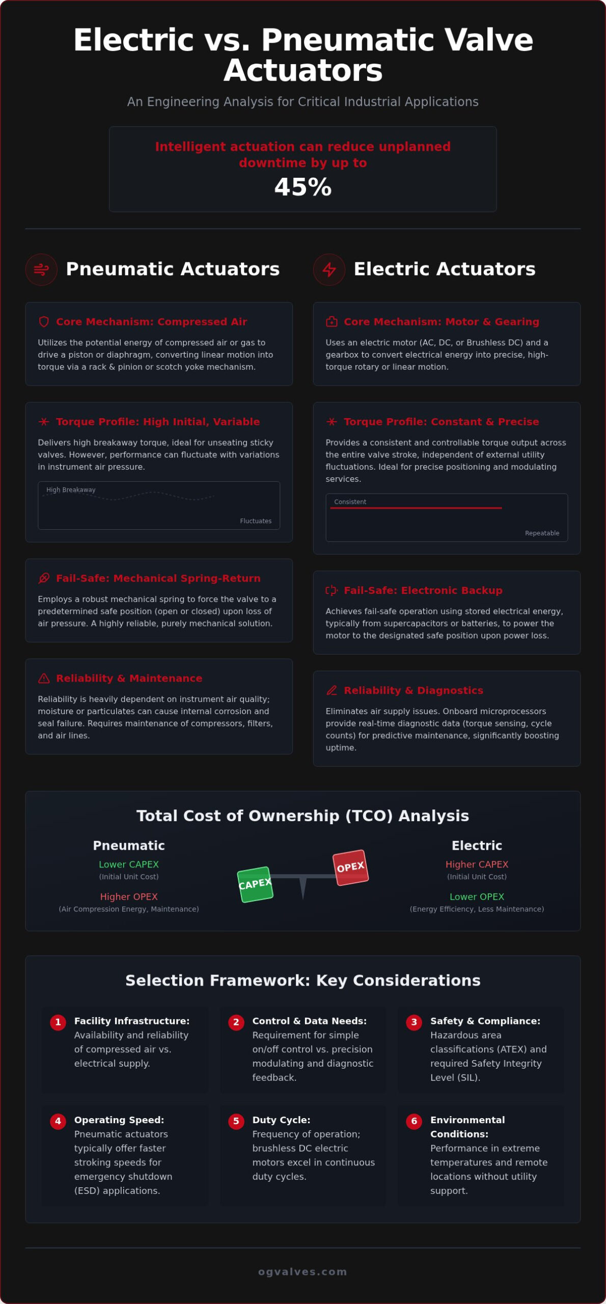
Does a 45% reduction in unplanned downtime justify the transition to intelligent actuation systems? For technical experts in the oil, gas, and power sectors, the choice between electric vs pneumatic valve actuators has shifted from a basic power preference to a critical engineering decision involving complex duty cycles and stringent regulatory adherence. You recognize that inaccurate fail-safe positioning during emergency shutdowns presents an unacceptable risk to facility integrity and personnel safety.
This article delivers an authoritative engineering analysis of power, performance, and reliability factors to guide your selection process for 2026. We provide a clear technical framework for choosing the optimal assembly, ensuring full compliance with SIL 2/3 and ATEX standards. You’ll gain a clinical evaluation of torque profiles, fail-safe accuracy, and the balance between CAPEX and OPEX according to the latest ISO 5211:2026 and EN ISO 5210:2026 requirements.
Key Takeaways
- Identify the fundamental differences between pneumatic energy storage and electric motor conversion to determine the most reliable power source for heavy industrial applications.
- Analyze breakaway torque requirements and operational speed profiles of electric vs pneumatic valve actuators to ensure precise control in high-pressure environments.
- Evaluate fail-safe functionality by comparing mechanical spring-return systems with supercapacitor backups to maintain compliance with SIL and ATEX safety standards.
- Assess the total cost of ownership through a clinical comparison of initial unit CAPEX against long-term infrastructure maintenance and energy consumption.
- Utilize a structured selection framework to match valve automation packages with specific facility utilities and operational duty cycles.
Core Functional Mechanisms: Power Sources and Control Logic
The fundamental engineering choice between electric vs pneumatic valve actuators rests on the method of energy conversion and the available facility infrastructure. A valve actuator serves as the critical interface between the control system and the physical process, converting either fluid pressure or electrical energy into mechanical torque. Pneumatic systems rely on the potential energy of compressed air, stored within a pressure vessel or distribution network, to drive a piston or diaphragm. Conversely, electric units utilize electromagnetic induction to rotate a motor shaft, which is then geared down to achieve the necessary output force for high-specification industrial ball valves.
Pneumatic Actuation: Compressed Air and Gas Dynamics
Pneumatic designs typically employ a rack and pinion or scotch yoke mechanism to translate linear piston movement into rotary motion. Double-acting configurations require air pressure for both opening and closing strokes, while spring-return (fail-safe) models utilize compressed air for one direction and mechanical spring tension for the other. Reliability in these systems is contingent upon the quality of the instrument air. The presence of moisture or particulates leads to internal corrosion and the eventual seizure of solenoid valves. In remote pipeline environments, engineers often leverage the process gas itself as the motive force, though this requires specialized seal materials to resist sour gas or corrosive media.
Electric Actuation: Precision and Motor Control
Electric actuation eliminates the operational risks of air line leaks and the significant maintenance overhead of industrial compressor stations. For high-torque requirements, three-phase motor configurations provide the necessary starting current and thermal stability to move heavy valve internals. Modern specifications increasingly favor brushless DC motors for continuous duty cycles. These motors offer superior heat dissipation and eliminate the wear components found in traditional brushed designs. Digital positioning is a primary advantage here; integrated encoders allow for precise travel limits without the mechanical complexity of external limit switch boxes.
Digital integration with a Distributed Control System (DCS) or Programmable Logic Controller (PLC) is inherently more streamlined in electric configurations. These units don’t require the intermediate I/P (current-to-pressure) transducers typically found in pneumatic setups. By utilizing onboard microprocessors, electric actuators provide real-time diagnostic data and torque sensing directly to the control room. This granular feedback loop is essential for predictive maintenance strategies in heavy industrial sectors where unplanned downtime results in severe economic loss.
Quantifying the mechanical output of electric vs pneumatic valve actuators requires an analysis of torque delivery across the full range of travel. Breakaway torque (BTO) represents the peak force required to unseat a valve member after a period of static residence. For high-pressure industrial ball valves, the BTO can be significantly higher than the running torque due to seat friction and fluid pressure differentials. Pneumatic systems deliver high initial torque but are susceptible to pressure fluctuations in the instrument air header. In contrast, electric units provide a constant torque profile, ensuring consistent operation regardless of external utility stability.
Torque and Thrust Characteristics
The selection process differs based on the valve’s mechanical motion. Multi-turn gate valves require precise linear thrust calculations to ensure the wedge seats firmly without damaging the stem threads. Electric actuators excel here by utilizing calibrated torque switches to prevent over-torquing. When specifying a butterfly valve, engineers must account for hydrodynamic torque, which varies based on flow velocity and disc position. While pneumatic actuators often require oversized cylinders to overcome these dynamic forces, modern electric units utilize adaptive torque control algorithms to maintain positioning accuracy. This technical precision is why many facilities now seek correctly specified actuated packages that match the actuator’s output curve to the valve’s torque demand.
Operational Speed and Responsiveness
Pneumatic actuators are the industry standard for emergency shutdown (ESD) scenarios. The rapid expansion of compressed air allows for stroking speeds of less than one second in critical fail-safe applications. Electric actuators traditionally operate at slower, fixed speeds. However, 2026 specifications for smart electric actuators now include adjustable speed parameters and controlled acceleration ramping. This feature is vital for preventing water hammer in liquid systems, where sudden valve closure can cause catastrophic pressure surges.
Duty cycle limitations represent a primary differentiator in high-frequency applications. Pneumatic actuators possess a near 100% duty cycle because the motive fluid effectively dissipates internal heat. Electric motors are subject to thermal build-up during frequent cycling. Specification for modulating service requires a clinical assessment of the motor’s S1 (continuous) or S4 (intermittent) duty rating to prevent premature insulation failure. Despite these thermal constraints, electric actuators are superior for precise throttling. They eliminate the “stick-slip” effect common in pneumatic positioners, providing a stable response for complex process control loops.
Reliability and Safety in Hazardous Industrial Environments
Safety in volatile atmospheres depends on rigorous adherence to international standards and the predictable behavior of equipment during power loss. When evaluating electric vs pneumatic valve actuators, the Safety Integrity Level (SIL) of the entire automated assembly takes precedence over individual component specifications. In 2026, SIL 2 or SIL 3 certification has become the baseline requirement for critical infrastructure. This certification ensures that the probability of failure on demand meets the strict safety requirements of offshore petrochemical facilities and power generation plants. Selecting an uncertified unit in these environments introduces unacceptable liability and operational risk.
Fail-Safe Logic and Emergency Operation
Pneumatic actuators provide inherent fail-safe functionality through mechanical spring-return designs. This stored energy requires no external power to return the valve to its designated safe position, whether fail-open or fail-closed. It’s a physical certainty that engineers rely on for high-speed isolation. Electric actuators historically lacked this mechanical energy storage, but modern designs now utilize industrial-grade battery backups or supercapacitors. These electronic fail-safe systems must undergo continuous diagnostic monitoring to verify their operational readiness. For manual intervention during total power loss, declutchable handwheels or hydraulic manual overrides provide a secondary layer of control, ensuring the facility remains under the operator’s command.
Structural Integrity and MAST Protection
A critical factor often overlooked in actuator selection is the Maximum Allowable Stem Torque (MAST). Oversizing an actuator presents a significant risk of stem shearing or internal valve damage if the valve becomes obstructed. Pneumatic systems are particularly susceptible to this if air pressure surges occur. Electric actuators mitigate this risk through integrated torque switches that cut power to the motor before the MAST limit is exceeded. This precision protects the valve’s structural integrity and extends the service life of the gear train. Adherence to ISO 5211 mounting standards ensures that the flange and drive interface can withstand the rated output without structural deformation or misalignment.
Explosion-proof housing is mandatory in zones containing combustible gases or dust. This requires dual ATEX and IECEx certification to ensure global regulatory compliance. In corrosive coastal or offshore environments, the material classification of the housing is as vital as the internal mechanics. While pneumatic units often utilize anodized aluminum or stainless steel, electric actuators require flame-proof enclosures that are also resistant to salt spray and chemical ingress. As a technical partner for correctly specified actuated packages, OG VALVES LTD. ensures that both the valve and the actuator assembly meet these demanding environmental and safety benchmarks.
Economic Analysis: CAPEX, OPEX, and Infrastructure Requirements
The economic evaluation of electric vs pneumatic valve actuators frequently suffers from a narrow focus on initial unit purchase price. While a pneumatic actuator generally commands a lower component CAPEX, the total system installation cost tells a different story. Pneumatic infrastructure requires extensive investment in compressor stations, high-capacity air receivers, and complex filtration and drying systems. Every meter of stainless steel instrument piping adds labor and material costs that don’t exist in electrical installations. Conversely, electric actuators only require power and signal cabling, which significantly reduces the footprint and complexity of the utility distribution network.
Operational expenditure is where the disparity becomes most evident. Compressed air is one of the most expensive utilities in a heavy industrial facility due to the inherent thermodynamic inefficiencies of compression. Modern smart actuators can achieve up to 40% energy savings through adaptive torque control algorithms that optimize power consumption based on real-time valve demand. Undetected air leaks in a pneumatic network represent a continuous, invisible drain on the facility’s budget. These leaks don’t just waste energy; they force compressors to cycle more frequently, accelerating wear and increasing the frequency of expensive overhaul intervals.
Total Cost of Ownership (TCO)
Maintenance profiles differ fundamentally between the two technologies. Pneumatic systems rely on elastomeric seals and O-rings that degrade over time due to friction and contaminants in the air supply. Replacing these components requires periodic downtime and manual intervention. Electric actuators utilize solid-state electronics and sealed gear trains that offer superior component longevity. The integration of IIoT in new smart installations now enables predictive maintenance protocols. By analyzing motor current and vibration data, these systems can reduce unplanned downtime by an estimated 30-45%, providing a quantifiable return on the higher initial investment.
Installation and Commissioning Complexity
Commissioning a pneumatic loop involves rigorous leak testing and the calibration of I/P transducers and positioners. This process is time-consuming and requires specialized technician hours. Electric systems simplify this phase through digital configuration. Many smart units feature non-intrusive setup via Bluetooth or infrared interfaces, allowing for rapid parameter adjustment without opening the enclosure. You can further reduce site-work by specifying pre-assembled actuated valve packages. For facilities looking to optimize their procurement strategy, it’s essential to partner with a supplier capable of providing technical procurement of actuated valve packages that arrive fully tested and ready for immediate integration into the plant DCS.
Selection Framework for Global Industrial Procurement
Engineering a reliable automation package requires a systematic evaluation of process demands and facility constraints. The decision between electric vs pneumatic valve actuators is best finalized through a four-stage technical audit. This framework ensures that the selected unit aligns with the operational output requirements and safety benchmarks of the facility. You must prioritize functional reality over initial cost to avoid long-term reliability deficits.
- Step 1: Define the primary function. Determine if the application requires basic On/Off isolation, precise Throttling for process control, or rapid Emergency Shutdown (ESD) capabilities.
- Step 2: Assess available utilities. Verify the stability of the electrical grid versus the capacity and quality of the instrument air infrastructure.
- Step 3: Evaluate environmental hazards. Confirm the required ATEX or IECEx zone classifications and account for temperature extremes that may affect seal integrity or electronic component performance.
- Step 4: Determine torque and thrust requirements. Calculate the necessary safety factors based on the valve’s breakaway torque and the Maximum Allowable Stem Torque (MAST) to prevent component shearing.
Application-Specific Recommendations
Pneumatic actuators remain the clinical choice for high-speed ESD applications and remote offshore sites where compressed gas is more readily available than stable high-voltage power. Their mechanical simplicity facilitates easier field repairs in isolated environments. Electric actuators are the superior specification for precise modulation in urban power plants and chemical processing facilities where digital integration with a DCS is paramount. For applications requiring extreme thrust beyond the capacity of standard units, electro-hydraulic actuators provide a hybrid alternative, combining electric control with the massive force density of hydraulic fluid.
Streamlining Global Supply Chains
Procurement specialists must account for the logistical complexities of international industrial projects. Reducing lead times is a critical factor in maintaining project schedules. OG Valves facilitates this through fast-track industrial valve delivery, ensuring that high-specification components reach the site without delay. We prioritize the provision of comprehensive documentation, including Material Test Reports (MTRs) and Factory Acceptance Test (FAT) certificates, as a non-negotiable standard for quality assurance.
Technical support from our headquarters ensures that your specification adheres to the latest ISO 5211:2026 mounting requirements. By providing both the valve and the correctly sized actuator as a unified assembly, we eliminate the risk of interface misalignment and ensure the structural soundness of the final package. This integrated approach simplifies the global supply chain and reinforces the position of OG Valves as a dependable partner in critical infrastructure projects.
Advancing Industrial Precision through Technical Specification
The clinical evaluation of electric vs pneumatic valve actuators confirms that neither technology represents a universal solution. Reliability depends on matching the actuator’s mechanical output to the specific torque profile of the valve internals. While pneumatic systems remain the baseline for high-speed fail-safe isolation, smart electric units provide superior precision and predictive maintenance data for continuous process control. It’s essential to adhere to the latest ISO 5211:2026 mounting standards and SIL 2/3 safety benchmarks to maintain infrastructure integrity. OG Valves delivers the technical expertise required to navigate these complex regulatory landscapes and high-pressure media applications. Our specialist procurement services ensure that every assembly meets the rigorous demands of the oil, gas, and power sectors. We facilitate global fast-track delivery to minimize project lead times and ensure operational readiness. Request a Technical Quote for Your Actuated Valve Package to secure a unified, API-compliant solution for your critical infrastructure. Your facility’s long-term performance starts with correctly specified automation.
Frequently Asked Questions
What are the main advantages of pneumatic actuators over electric ones?
Pneumatic actuators provide a higher power-to-weight ratio and inherent fail-safe capabilities through mechanical spring-return designs. These units are specifically suited for high-speed operation and hazardous environments where explosion-proof electric enclosures would be cost-prohibitive. Their mechanical simplicity allows for high-cycle durability in remote or offshore locations where electronic diagnostic support is limited, ensuring reliable performance in corrosive media applications.
Can an electric actuator be used for emergency shutdown (ESD) applications?
Yes, modern electric actuators are suitable for emergency shutdown applications when equipped with industrial-grade battery backups or supercapacitors. These energy storage systems allow the unit to reach its fail-safe position during a total loss of facility power. However, engineers must verify that the electronic fail-safe response time meets the specific safety requirements defined in the facility’s SIL 2 or SIL 3 risk assessment.
Which actuator type is more energy-efficient for large industrial plants?
Electric actuators are significantly more energy-efficient than pneumatic systems because they only consume power during movement. In a clinical comparison of electric vs pneumatic valve actuators, pneumatic systems suffer from constant energy loss due to air leaks and the high thermodynamic cost of operating industrial compressor stations. Large plants often find it’s more cost-effective to offset the higher CAPEX of electric units with lower utility expenses.
How does ambient temperature affect the performance of pneumatic actuators?
Extreme ambient temperatures affect pneumatic performance by altering the viscosity of internal lubricants and the elasticity of elastomeric seals. In sub-zero environments, moisture in the instrument air supply can freeze, causing pilot valve seizure or blockage in the distribution piping. High temperatures accelerate seal degradation and can lead to pressure-retaining component failure if the material classifications don’t meet environmental thermal limits.
What is the significance of the duty cycle in electric valve actuation?
The duty cycle defines the ratio of operating time to rest time required to prevent motor overheating. For modulating service, a 100% duty cycle rating is essential to ensure the motor can handle continuous positioning adjustments without thermal trip-outs. Selecting a motor with an insufficient duty cycle leads to premature insulation failure and unplanned operational downtime in high-frequency control loops.
Is it possible to convert a manual valve to an automated one using both types?
Conversion of manual valves to automated assemblies is possible for both actuator types provided the mounting interface complies with ISO 5211 standards. The process requires a custom mounting kit consisting of a bracket and drive coupler to bridge the valve stem and the actuator drive. Procurement specialists must ensure the chosen electric vs pneumatic valve actuators don’t lack the torque required to overcome breakaway torque requirements after long periods of inactivity.
What maintenance is required for pneumatic actuator solenoid valves?
Maintenance for pneumatic solenoid valves focuses on ensuring the integrity of the coil and the cleanliness of the internal pilot orifices. Regular inspection involves checking for air leaks at the exhaust ports and verifying the absence of moisture or oil in the air supply, which causes spool stiction. Replacing worn O-rings and cleaning the pilot assembly prevents sluggish response times or failure to stroke during critical process events.
How do I determine if my valve requires a multi-turn or quarter-turn actuator?
The valve’s internal closure mechanism determines the required actuator motion. Quarter-turn actuators are specified for ball, butterfly, and plug valves that transition from open to closed within a 90-degree rotation. Multi-turn actuators are necessary for gate and globe valves, where the stem must rotate several times to raise or lower the seating element. If you don’t correctly match the motion type, it results in mechanical interference or failure to achieve a bubble-tight seal.
 Responsive Menu