The assumption that globe valves are interchangeable with gate valves for simple isolation is a foundational error that compromises system integrity and regulatory standing. While both facilitate flow control, the specific mechanics of industrial globe valve applications demand a more rigorous technical assessment to avoid catastrophic pressure drops and internal cavitation. You likely recognize that incorrect specification leads to rapid erosion in throttling services, yet identifying the precise configuration for high-pressure media remains a complex engineering challenge that requires deep familiarity with material traceability.
This guide provides a clinical analysis of globe valve mechanics, comparative advantages, and their critical deployment in high-pressure industrial fluid regulation. We’ll evaluate the mechanical limits of throttling to ensure your systems remain compliant with current API 623 and ASME B16.34 standards. This technical overview moves from basic configuration selection for specific media to a detailed examination of 2026 EU safety regulations and global benchmarks for structural soundness. By the end of this analysis, you’ll be equipped to specify components that withstand the most demanding operational environments while maintaining total adherence to international safety protocols.
Key Takeaways
- Evaluate the mechanical advantages of the tortuous flow path for precise fluid regulation where gate and ball valves fail under high-stress throttling conditions.
- Distinguish between T-Pattern, Y-Pattern, and Angle body configurations to optimize system layout and minimize pressure drops in high-pressure environments.
- Examine critical industrial globe valve applications across the oil, gas, and power sectors, with a specific focus on managing high-pressure steam and chemical injection.
- Align procurement strategies with 2026 international benchmarks, including API 623 and ASME B16.34, to ensure structural soundness and regulatory adherence.
- Secure critical infrastructure by prioritizing material traceability and Mill Test Reports (MTRs) to mitigate the risks of erosion and cavitation in specialized environments.
Principles of Throttling: The Mechanical Role of Globe Valves in Fluid Control
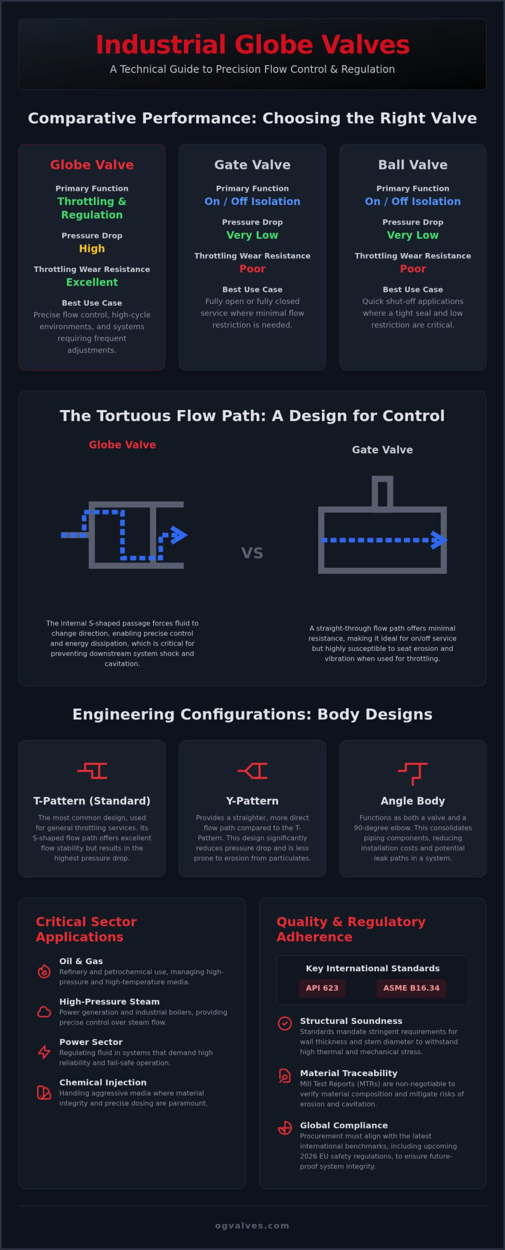
Industrial globe valve applications are defined by their capacity for precise flow regulation rather than simple on-off service. A globe valve is a linear-motion, often power-operated component designed specifically to stop, start, and regulate fluid movement through a system. The core of its functionality lies in the internal geometry of the body, which forces the media through a tortuous flow path. This deliberate redirection of fluid is essential for managing the kinetic energy of the process stream. The fundamental mechanism involves the perpendicular movement of the disc relative to the seat, ensuring a uniform contact area that facilitates precise throttling. Unlike gate valves, which suffer from seat erosion when partially open, the globe design maintains mechanical integrity during frequent adjustments, making it the standard for high-cycle environments.
The Fluid Dynamics of the S-Shaped Flow Path
The internal S-shaped passage is the defining characteristic of globe valve fluid dynamics. While this path results in a higher pressure drop compared to straight-through designs, it allows for exceptional control over the flow coefficient (Cv). The relationship between the disc position and the seat orifice enables fine-tuned adjustments to the fluid volume. This tortuous path serves a secondary purpose: it facilitates energy dissipation and manages turbulent flow. By forcing the fluid to change direction multiple times, the valve effectively reduces the velocity and pressure of the media, which is critical in preventing downstream system shock. Understanding these Principles of globe valve design is necessary for engineers managing cavitation risks in high-velocity systems.
Standardization and Regulatory Benchmarks (API 623 & BS 1873)
Strict adherence to international standards ensures the reliability of globe valves in heavy industrial sectors. API 623 is the primary standard for steel globe valves, specifically addressing flanged or butt-welding ends for refinery and petrochemical use. This standard represents a significant evolution from the older BS 1873 specifications, introducing more stringent requirements for wall thickness and stem diameters. These parameters aren’t arbitrary; they’re calculated to withstand the high thermal and mechanical stresses encountered in high-pressure industrial globe valve applications. Modern procurement must verify that components meet these updated benchmarks to guarantee structural soundness and prevent fugitive emissions. Material traceability remains a non-negotiable requirement for any system operating under these rigorous regulatory frameworks.
Engineering Configurations: T-Pattern, Y-Pattern, and Angle Body Designs
Body pattern selection is a primary engineering decision that balances flow efficiency against the necessity for precise regulation. In industrial globe valve applications, the specific geometry of the valve body directly impacts the permanent pressure loss and the mechanical stability of the system. Selecting the correct configuration requires a rigorous analysis of allowable pressure drop, system layout, and the physical properties of the media. The bonnet assembly performs a critical function by maintaining stem seal integrity under extreme thermal stress, preventing fugitive emissions in high-temperature services. While carbon steel is the baseline for many refinery services, aggressive media require a transition to specialized materials like super duplex alloys to mitigate localized corrosion and pitting.
T-Pattern (Standard) and Angle Body Variations
The T-pattern is the industry standard for general throttling where a high pressure drop is acceptable or even required to achieve flow stability. It’s the most common configuration in petrochemical plants due to its straightforward design and ease of maintenance. Angle body designs offer a distinct advantage by functioning as both a control valve and a 90-degree elbow. This consolidation reduces the total number of piping components and potential leak paths. These variations are particularly effective for handling high-viscosity fluids and pulsating flows where turbulence must be managed without compromising seat life. For projects requiring precise material traceability, consulting a global supplier of high-specification valves ensures that every component meets rigorous PMI testing standards.
Y-Pattern Globe Valves for Low Pressure Drop
Y-pattern configurations address the inherent flow resistance of the standard globe design. The structural benefit of the Y-pattern design lies in its ability to align the stem and seat at a 45-degree angle to the flow path, which significantly reduces the resistance encountered by the fluid. By positioning the stem and seat at an angle, the fluid maintains a straighter path through the valve body. This design is essential in high-pressure steam and critical boiler feedwater systems where energy efficiency and low pressure loss are prioritized. Compared to the T-pattern, the Y-pattern offers a higher flow coefficient while retaining the precise throttling capabilities of the globe mechanism. This configuration is often specified to meet ASME B16.34 requirements in high-velocity steam lines.

In critical industrial globe valve applications, the selection of a valve type is dictated by the mechanical requirements of flow regulation. While gate valves excel in full-isolation service, their sliding wedge mechanism is fundamentally unsuited for throttling. When a gate valve is partially open, high-velocity fluid causes severe seat erosion and “wire-drawing,” a phenomenon where the media cuts a groove into the sealing surface. This results in permanent leakage and structural failure. Conversely, the globe valve’s plug-and-seat design ensures that the contact area remains uniform, preserving the integrity of the seal even under constant adjustment. For a broader perspective on selection criteria, refer to Industrial Valves: The Engineer’s Comprehensive Guide.
Ball valves are frequently specified for their rapid quarter-turn operation, yet they lack the precision necessary for granular flow control. The rapid opening characteristic of a ball valve creates a non-linear flow curve that is difficult to calibrate in automated systems. Globe valves provide a predictable, linear relationship between stem travel and flow rate. This mechanical advantage is vital in high-pressure gas injection systems where incremental adjustments are required to maintain process stability. While ball valves offer a lower initial profile, they cannot match the fine-tuned rangeability inherent in the linear-motion globe design.
Throttling Precision and Rangeability
Rangeability defines the ratio between the maximum and minimum controllable flow rates. Globe valves exhibit superior rangeability because the disc moves directly into the flow stream, allowing for precise modulation at the low end of the stroke. This design also ensures a tighter shut-off compared to many butterfly alternatives, which often struggle with seal deformation under high differential pressures. In high-stakes industrial globe valve applications, this precision prevents the system instability often caused by the “hunting” of less accurate valve types during low-flow conditions.
Operational Lifespan and Maintenance Cycles
The maintenance profile of a globe valve is a significant factor in long-term operational output. Unlike ball valves, which often require complete unit replacement when internal seats fail, globe valves allow for seat resurfacing and disc replacement in many configurations. High-frequency cycling does place specific stress on stem packing and seal life, necessitating rigorous quality assurance. Understanding these trade-offs is essential for maintaining infrastructure longevity. For detailed comparisons with other isolation tools, consult A Technical Guide to Industrial Gate Valves.
Critical Sector Applications: Oil, Gas, and High-Pressure Steam Systems
Industrial globe valve applications are fundamental to the operational safety of high-stakes infrastructure. In the upstream oil and gas sector, these valves are deployed at the wellhead to manage high-pressure fluids and facilitate precise chemical injection into the process stream. The ability to maintain stable flow rates under extreme differential pressures prevents system surges that could compromise downstream equipment. Within petrochemical processing, the focus shifts to the containment of volatile organic compounds (VOCs). Here, bellows-sealed bonnets are the technical standard, providing a hermetic seal that ensures zero leakage and total regulatory compliance. Cooling water systems also utilize globe valves to throttle flow to heat exchangers, a process that requires constant adjustment to maintain thermal equilibrium across the facility.
Managing Cavitation and Flashing in Steam Service
Steam service presents unique mechanical challenges, specifically the physics of cavitation and flashing. When a high pressure drop occurs across the valve seat, the fluid may vaporize, forming bubbles that subsequently collapse and cause localized material erosion. Specifying anti-cavitation trim is a critical requirement to mitigate this risk. In high-temperature environments exceeding 500°C, material selection must prioritize creep resistance. ASTM A217 Gr. C12A is frequently specified for its durability in these conditions. Beyond material integrity, design modifications like multi-path trim are essential for noise reduction in high-velocity gas applications, protecting both the hardware and the operational environment from acoustic vibration.
Chemical Injection and Corrosive Media Handling
Handling aggressive chemical media requires a specialized approach to trim selection. Materials such as Stellite, Monel, and Hastelloy are utilized to prevent rapid degradation in corrosive environments. The necessity of Positive Material Identification (PMI) testing cannot be overstated during the procurement process. This testing verifies that the alloy composition matches the technical specification, preventing the installation of sub-standard components in critical lines. To meet 2026 environmental standards, valves must also feature fugitive emission-certified packing. This ensures that even under high-cycle conditions, the valve remains a secure point in the infrastructure. For technical support in selecting the correct configuration for your project, consult our specialists for high-specification valve procurement.
Procurement and Quality Assurance for High-Specification Globe Valves
Procuring components for industrial globe valve applications requires a rigorous technical assessment that extends beyond basic dimensions. Procurement officers must prioritize pressure-temperature ratings and end connection specifications, such as flanged or butt-welding ends, to ensure compatibility with existing infrastructure. Material traceability is a non-negotiable requirement in high-stakes sectors; every component must be accompanied by comprehensive Mill Test Reports (MTRs). These documents provide the verifiable data necessary to confirm that the chemical composition and mechanical properties of the valve body and trim meet the project’s specific safety benchmarks. Relying on a global supplier with established inventory management protocols is essential for minimizing operational downtime during critical maintenance windows.
Rigorous Testing Protocols: Hydrostatic and PMI
Every valve must undergo standardized testing to validate its structural soundness before deployment. The primary reference for these procedures is API 598, which outlines the requirements for hydrostatic shell and seat tests. These tests are conducted at pressures exceeding the rated working limit to ensure there are zero visible leaks. In addition to hydrostatic testing, Positive Material Identification (PMI) is utilized to verify alloy integrity in high-stress environments. Non-destructive testing (NDT) options further enhance quality assurance:
- Radiographic Testing (RT): Utilized primarily for cast valve bodies to detect internal volumetric defects.
- Ultrasonic Testing (UT): Effective for forged components to identify sub-surface flaws in the material structure.
- Magnetic Particle Inspection (MPI): Used to detect surface and near-surface discontinuities in ferromagnetic materials.
Optimizing Global Supply for Minimal Downtime
Strategic inventory management and global logistics are critical for maintaining infrastructure longevity. OG VALVES LTD. acts as a dependable partner by providing fast-track delivery of high-specification components, ensuring that critical infrastructure remains operational. Technical consulting is a standard part of our procurement support; we ensure that every valve matches the specific pressure-temperature curve of the facility. By anchoring our supply chain in rigorous testing and international certifications, we provide the reliability required for heavy industrial sectors. Consult with OG VALVES for high-specification globe valve procurement to secure your facility’s operational output.
Advancing System Reliability Through Technical Specification
The complexity of industrial globe valve applications requires a transition from general procurement to high-specification engineering. By prioritizing the mechanical advantages of the tortuous flow path and selecting configurations like Y-pattern designs for reduced pressure loss, operators can effectively mitigate the risks of cavitation and erosion. Adherence to 2026 benchmarks such as API 623 and ASME B16.34 ensures that components withstand the thermal and mechanical stresses inherent in the oil, gas, and power sectors. Maintaining structural soundness through rigorous PMI testing and material traceability remains the only viable strategy for long-term infrastructure integrity.
As specialist suppliers to the petrochemical and power sectors, OG VALVES LTD. provides the technical expertise in API and ASME valve standards necessary for high-stakes deployment. We prioritize fast-track global delivery for critical industrial components to minimize operational downtime and maintain system output. Our commitment to rigorous quality assurance ensures that every component performs reliably under the most demanding conditions. Request a Technical Quote for Industrial Globe Valves to secure your facility’s long-term operational performance.
Frequently Asked Questions
What is the primary difference between a globe valve and a gate valve?
The primary distinction lies in their functional intent. Gate valves are designed for full isolation with minimal pressure drop, while globe valves are engineered for throttling and flow regulation. The internal geometry of the globe valve forces media through a tortuous path, allowing for precise control. Conversely, the sliding wedge of a gate valve suffers from rapid erosion if used in a partially open position, making the globe design essential for regulation.
Can globe valves be used for bi-directional flow?
Globe valves are typically designed for uni-directional flow. The direction of the media is critical for maintaining seat integrity and ensuring a bubble-tight shut-off. While some specialized designs exist, the standard configuration requires the flow to enter under the disc to facilitate easier opening and prevent stem packing stress. Incorrect installation against the specified flow direction can lead to mechanical vibration and premature component failure, compromising the structural soundness of the system.
What are the main causes of globe valve failure in high-pressure steam systems?
Failure in high-pressure steam systems is often attributed to cavitation and wire-drawing. When high-velocity steam passes through a partially open valve, it can erode the seat and disc surfaces, creating permanent leak paths. Thermal fatigue and creep also compromise the structural soundness of the valve body over time. Utilizing materials like ASTM A217 Gr. C12A and specifying anti-cavitation trim are necessary steps to mitigate these specific operational risks in steam service.
How does the Cv value of a globe valve compare to a ball valve of the same size?
A globe valve typically exhibits a significantly lower flow coefficient (Cv) than a ball valve of the identical size. The internal S-shaped flow path of the globe design creates inherent resistance, which is the trade-off for its superior throttling precision. A ball valve provides a virtually unobstructed flow path when fully open, resulting in higher Cv and lower pressure drop. This makes globe valves better suited for regulation and ball valves better for isolation.
When should a Y-pattern globe valve be specified over a T-pattern?
A Y-pattern globe valve should be specified when the application requires precise throttling but necessitates a lower pressure drop than a standard T-pattern. By aligning the stem and seat at a 45-degree angle, the Y-pattern reduces flow resistance while maintaining regulation capabilities. This configuration is frequently selected for high-pressure steam lines and feedwater systems where energy efficiency is a priority for the facility’s operational output and long-term infrastructure integrity.
Are globe valves suitable for slurry or high-solids applications?
Standard globe valves are generally unsuitable for slurry or high-solids applications. The tortuous flow path and the seat-and-disc arrangement provide areas where solids can accumulate, leading to clogging and seat damage. For these specialized environments, other valve types like plug valves or specific ball valve configurations are often more durable. In industrial globe valve applications, the media should ideally be clean fluids or gases to prevent localized erosion and ensure long-term performance.
What international standards govern the manufacture of industrial globe valves?
The manufacture of these valves is governed by several international benchmarks. API 623 is the primary standard for steel globe valves in heavy industrial use, succeeding the older BS 1873. Pressure-temperature ratings are defined by ASME B16.34, while API 598 dictates the mandatory testing protocols, including hydrostatic and seat leakage tests. Adherence to these standards is a critical requirement for ensuring regulatory compliance and structural integrity in high-pressure industrial systems.
Is it possible to automate a globe valve for remote flow control?
It’s entirely possible to automate a globe valve for remote flow control using pneumatic, hydraulic, or electric actuators. Because globe valves are linear-motion components, they integrate effectively with actuators to provide precise, automated throttling. This is a common requirement in modern industrial facilities where IIoT sensors and smart technologies are used for predictive maintenance. Automation ensures consistent performance in critical industrial globe valve applications across the global oil and gas sectors.
 Responsive Menu