Specifying a gate valve where a globe valve is required isn’t just a minor design oversight; it’s a guaranteed catalyst for premature seat erosion and systemic pressure instability. In high-stakes industrial environments, the distinction between isolation efficiency and throttling precision defines the boundary between operational excellence and catastrophic component failure. Engineering teams often struggle to balance immediate procurement cycles with the necessity for long-term mechanical integrity. You know that an incorrect specification leads to high pressure drops and frequent maintenance intervals that compromise your facility’s output.
This technical analysis provides a definitive comparison of the gate valve vs globe valve, focusing on the structural mechanics and flow dynamics essential for modern infrastructure. We’ll examine how adherence to the latest API 600 14th edition and API 623 2022 standards ensures regulatory compliance and safety. This guide delivers a clinical evaluation of seat design, disc geometry, and pressure-temperature ratings. We’ll also preview how specific material classifications and ASME B16.34-2020 benchmarks influence valve longevity in corrosive or high-velocity service. By the end of this analysis, you’ll have the data required to optimize flow control and minimize the total cost of ownership for your critical valve inventory.
Key Takeaways
- Distinguish between parallel or wedge-shaped gate sealing and the tortuous S-path geometry of globe valves to prevent mechanical misapplication in high-pressure systems.
- Analyze the functional trade-offs in the gate valve vs globe valve selection process, specifically regarding zero-obstruction isolation versus precise flow regulation.
- Quantify the operational impact of Flow Coefficient (Cv) values and pressure drops to optimize fluid transport efficiency and reduce pump power requirements.
- Validate system compliance by referencing specific industrial benchmarks, including the latest API 600, API 623, and ASME B16.34-2020 standards.
- Utilize a technical decision matrix to align media type and pressure classes with long-term maintenance cycles and reduced operational downtime.
Structural Mechanics: Internal Design Divergence
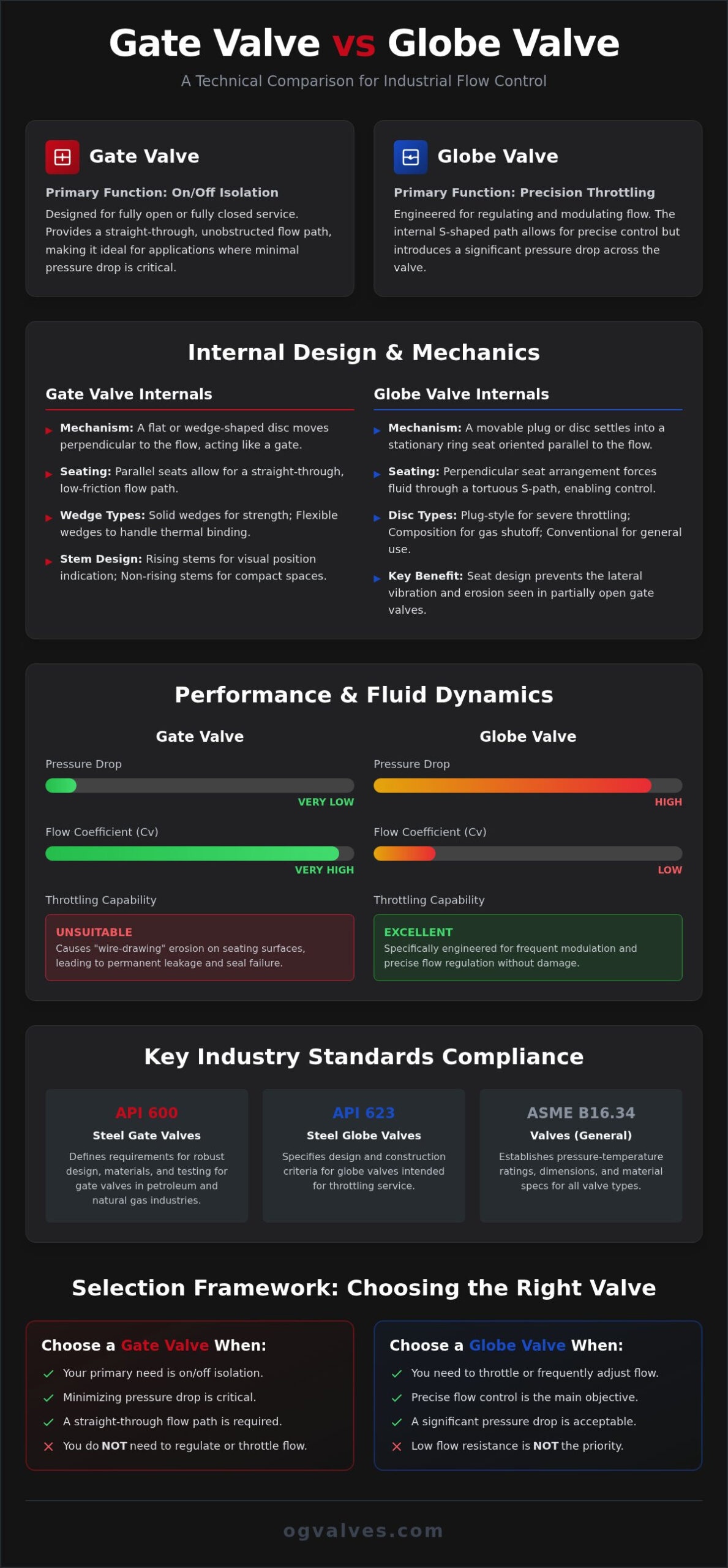
The mechanical operation of both units relies on a linear motion stem. This component converts rotational torque from the actuator or handwheel into vertical thrust. It’s the internal geometry that defines the divergence in the gate valve vs globe valve performance profile. Gate valves utilize a flat or wedge-shaped barrier that moves perpendicular to the flow. It’s the primary reason they provide minimal resistance in the fully open position. In contrast, globe valves employ a movable plug or disc that settles into a stationary ring seat, typically oriented parallel to the fluid direction.
Seating orientation dictates the unit’s utility. Gate valves feature parallel seats that allow for a straight-through flow path, minimizing friction. Globe valves utilize a perpendicular seat arrangement that forces media through a tortuous S-shaped path. This design creates the turbulence necessary for regulated flow control but introduces significant pressure drop across the valve body. Because the seat is parallel to the flow in a globe valve, the kinetic energy of the fluid doesn’t cause the same lateral vibration issues found in partially open gate valves.
Gate Valve Internals: Sealing Integrity
The architecture of a gate valve focuses on achieving a bubble-tight shutoff in isolation service. Engineers must specify wedge types based on thermal conditions. Solid wedges offer high structural strength but are susceptible to thermal binding in high-temperature cycles. Flexible wedges incorporate a machined groove that allows the seating surfaces to deflect, accommodating pipe loads and thermal expansion. Seat rings, often hard-faced with Stellite, provide the durable contact surface required for API 600 compliance. Stem design also impacts the footprint:
- Rising Stem: Provides immediate visual verification of valve position; requires greater vertical clearance.
- Non-Rising Stem: Internal threads move the gate without raising the stem, suiting tight spaces.
Globe Valve Internals: The Throttling Plug
Globe valve design prioritizes the integrity of the plug and seat interface under high-pressure differentials. The contact surface area is larger than that of a gate valve, which enhances sealing precision during regulation. Manufacturers utilize top-entry body designs to facilitate in-line maintenance, allowing technicians to inspect the seat and disc without removing the valve from the piping system. Selecting the correct disc type is critical for operational output. Understanding the mechanical nuances of a gate valve vs globe valve prevents the use of inappropriate components in severe service applications. Common disc configurations include:
- Plug-Style Disc: Features a long, tapered configuration for superior throttling in severe service.
- Composition Disc: Uses a non-metallic insert to ensure positive shutoff in low-pressure gas applications.
- Conventional Disc: A metal-to-metal seat suited for general utility and low-frequency throttling.
Operational Functionality: Isolation vs. Precision Throttling
The primary operational distinction in the gate valve vs globe valve comparison lies in the intended service type. Gate valves are designed strictly for on/off isolation where the unit remains either fully retracted or fully seated. Globe valves are engineered for precision throttling and frequent modulation. Attempting to throttle with a gate valve induces “wire-drawing.” This phenomenon occurs when high-velocity fluid erodes the seating surfaces of a partially open wedge, resulting in a permanent loss of sealing integrity. Once wire-drawing occurs, the valve cannot achieve a bubble-tight shutoff even when fully closed.
Both designs utilize multi-turn operation, which results in slower response times compared to quarter-turn alternatives. While this prevents water hammer in large-diameter systems, it requires significant manual or automated effort for full actuation. For high-stakes infrastructure, procurement teams should evaluate technical valve specifications to ensure the chosen mechanism matches the system’s operational frequency. Slower actuation is a deliberate safety feature in high-pressure steam and hydrocarbon lines to manage kinetic energy transitions.
Isolation Efficiency in Gate Valves
Gate valves provide a full-bore, straight-through flow path that minimizes turbulence. This makes them ideal for “piggable” pipelines where cleaning tools must pass through the valve body without obstruction. Their bi-directional sealing capability allows for flexible system layouts, as the valve functions effectively regardless of flow direction. However, the sliding motion of the gate against the seats causes friction. High-frequency cycling quickly degrades these contact points, leading to leakage. Consequently, they’re reserved for main isolation points rather than control loops.
Flow Regulation in Globe Valves
Globe valves offer superior linearity in flow control. The relationship between stem position and the flow orifice is predictable, allowing for precise calibration of system output. These units are better suited for high pressure differentials because the disc moves directly into the flow path rather than across it. Most globe valves require uni-directional installation. “Flow-under-disc” configurations are standard to assist in valve opening and prevent stem vibration. In contrast, “flow-over-disc” may be specified for high-pressure steam closure to ensure the valve remains shut during a loss of power.
Fluid Dynamics: Analyzing Pressure Drop and Cv
Fluid dynamics represent the most significant performance variance in the gate valve vs globe valve evaluation. While structural mechanics define durability, the internal flow path dictates the system’s hydraulic efficiency and long-term energy expenditure. Flow Coefficient (Cv) is defined as the volume of water at 60°F that will flow through a valve with a pressure drop of 1 psi. Because gate valves provide a full-port, unobstructed bore, they exhibit exceptionally high Cv values. This makes them the engineering standard for high-volume transport where maintaining system pressure is paramount.
Globe valves utilize an S-shaped internal body that forces media through two 90-degree turns. This tortuous path generates high resistance even when the valve is fully open, resulting in a significantly lower Cv compared to a gate valve of the same nominal size. While this geometry is essential for the precision required in throttling service, it introduces substantial turbulence. Engineers must account for these fluid dynamic profiles when calculating pump head requirements and overall system efficiency to prevent operational bottlenecks.
Head Loss and Energy Efficiency
Quantifying the K-factor, or resistance coefficient, is essential for accurate system modeling. Full-bore gate valves typically exhibit K-factors as low as 0.15 to 0.2, representing negligible head loss. In contrast, globe valves often feature K-factors exceeding 5.0. Understanding the gate valve vs globe valve pressure profiles is vital for selecting the valve geometry that aligns with the system’s energy efficiency targets. High head loss translates directly to increased pumping power requirements and higher utility costs. Additionally, the increased media velocity through the globe valve’s restricted orifice can accelerate seat erosion, particularly in abrasive or high-viscosity services.
Cavitation and Noise Mitigation
Throttling applications in globe valves introduce the risk of cavitation, a phenomenon where local pressure drops below the fluid’s vapor pressure. When vapor bubbles collapse against the valve trim, they cause pitting and mechanical vibration. Identifying the cavitation index is a prerequisite for selecting appropriate trim materials and avoiding component failure. In high-velocity steam or gas services, noise reduction strategies are equally important. Anti-cavitation trim options, such as multi-stage discs or perforated cages, help dissipate kinetic energy. These specialized components reduce noise levels and protect the structural integrity of the valve body during severe service regulation, ensuring compliance with industrial safety standards regarding acoustic emissions.
Compliance and Specifications: ASME and API Standards
Adherence to rigorous regulatory frameworks ensures the structural soundness of industrial piping systems. The specification of a gate valve vs globe valve must align with established benchmarks from the American Petroleum Institute (API) and the American Society of Mechanical Engineers (ASME). ASME B16.34-2020 serves as the foundational standard for pressure-temperature ratings, defining the operational limits for flanged, threaded, and welding-end valves. For gate valves, API 600 14th edition governs heavy-duty steel constructions, while API 603 addresses specific corrosion-resistant requirements for stainless steel units.
The 2022 edition of API 623 has standardized steel globe valves for severe service, bridging the gap that previously existed in globe valve certification. This standard mandates thicker stems and more robust seat-to-disc interfaces to withstand extreme pressure differentials without mechanical deformation. Additionally, environmental compliance is dictated by API 622, which establishes strict limits for fugitive emissions from stem packing. Procurement experts should consult technical valve inventory to verify that components meet these evolving safety benchmarks and international safety regulations.
Material Selection for Heavy Industry
Material traceability is non-negotiable in petrochemical and power applications. ASTM A216 WCB remains the industry standard for carbon steel bodies in non-corrosive service, whereas CF8M, or Stainless Steel 316, is required for acidic or oxidizing media. To mitigate the wear associated with high-velocity flow, seating surfaces frequently receive Stellite hardfacing. This cobalt-base alloy provides the necessary hardness to resist erosion and galling during high-frequency operation. In upstream oil and gas sectors, NACE MR0175 compliance is essential to prevent sulfide stress cracking in sour gas environments containing hydrogen sulfide.
Quality Assurance and Testing Protocols
Validation of valve integrity occurs through rigorous testing protocols defined by API 598. This includes shell pressure tests, backseat verification, and closure leakage assessments to ensure bubble-tight performance. For high-alloy components, Positive Material Identification (PMI) utilizes X-ray fluorescence to verify chemical composition before shipment. Non-Destructive Testing (NDT) further ensures internal soundness. Radiographic testing identifies sub-surface casting defects, while ultrasonic testing measures wall thickness and detects laminar flaws. These clinical processes ensure that the final product maintains its performance under extreme industrial loads without the risk of catastrophic failure.
Industrial Selection Framework: Optimising System Reliability
Selecting between a gate valve vs globe valve requires a methodical evaluation of the media’s physical properties and the system’s operational frequency. A robust decision matrix must account for media viscosity, pressure class, and the specific role of the unit within the process loop. Procurement specialists often focus on initial capital expenditure, but it’s the Total Cost of Ownership (TCO) that serves as the true measure of reliability. This metric accounts for scheduled maintenance cycles, energy losses due to pressure drop, and the significant cost of unplanned downtime. Understanding the trade-offs of the gate valve vs globe valve ensures that the chosen unit matches the pressure class and media type of the application.
Space and weight constraints also influence the final specification. Gate valves typically feature a more compact face-to-face dimension, which is critical in modular skid construction where weight is a primary design driver. Globe valves, due to their complex internal S-path and vertical stem travel, require larger bodies and more robust actuation systems. Procurement teams don’t just look at the hardware; they evaluate the supplier’s ability to maintain high-stakes trust. OG VALVES LTD. facilitates technical procurement for global projects by providing fast-track delivery of high-specification inventory. Our technical support teams ensure every component adheres to the clinical requirements of the petrochemical and power sectors, acting as a dependable partner in critical infrastructure.
When to Specify a Gate Valve
Gate valves are the preferred solution for main isolation lines in crude oil transport and wastewater management. Their ability to provide a full-bore, unobstructed path is essential for systems requiring periodic pigging operations or high-volume fluid transfer. In high-temperature steam applications where pressure drop must be minimised to maintain thermal efficiency, the gate design’s low resistance coefficient (K-factor) provides a distinct advantage over more restrictive alternatives. For detailed engineering data on material classifications and seat designs, refer to our Technical Guide to Industrial Gate Valves which covers design standards and selection criteria for 2026.
When to Specify a Globe Valve
Globe valves are indispensable for boiler feed water systems and cooling water regulation where precise volumetric control is mandatory. Unlike gate designs, they maintain mechanical integrity under high-pressure differentials and frequent modulation. Chemical injection points also require the linear flow characteristics provided by a globe valve’s plug-style disc to ensure accurate dosing. The ability to perform in-line seat maintenance further enhances their suitability for critical control loops. For a broader analysis of selection frameworks across different valve categories, consult the Industrial Valves Guide. This resource assists engineers in aligning valve capabilities with complex system demands and international safety regulations.
Securing Infrastructure Through Engineering Precision
The technical divergence in a gate valve vs globe valve dictates the operational limits of high-stakes industrial piping. Successful system integration depends on aligning internal geometry with specific flow requirements; this involves prioritizing the zero-obstruction isolation of a gate valve or the precision throttling capabilities of a globe valve. Adherence to API 600 and API 623 standards remains the essential benchmark for ensuring component durability and regulatory compliance across petrochemical and power sectors.
Optimizing industrial output requires a clinical focus on material traceability and flow dynamic efficiency. OG VALVES LTD. maintains a high-specification inventory that is fully compliant with API 600 and API 623 benchmarks. We facilitate global fast-track delivery to heavy industry sites, supported by specialist technical support for procurement teams to ensure rigorous engineering standards are met without compromise. Every installation represents a commitment to safety and operational output. It’s the technical data that drives these decisions, ensuring long-term mechanical integrity in critical infrastructure.
Request a Technical Quote for Industrial Gate and Globe Valves to ensure your infrastructure operates with unwavering reliability.
Frequently Asked Questions
Can a gate valve be used for throttling in an emergency?
No, using a gate valve for throttling, even in emergencies, typically results in permanent seat damage known as wire-drawing. The high-velocity fluid flow across a partially open wedge creates turbulence that erodes the sealing surfaces. This prevents the valve from achieving a bubble-tight shutoff once returned to the closed position. For emergency regulation, engineers should rely on dedicated control valves or globe valves designed to withstand the kinetic energy of modulated flow.
Why do globe valves have a specific flow direction?
Globe valves require a specific flow direction due to their internal S-shaped body and the orientation of the disc relative to the seat. Most industrial applications utilize a “flow-under-disc” configuration to assist in opening the valve and to reduce the load on the stem packing when the unit is open. Installing the valve in the incorrect orientation can lead to severe stem vibration, increased torque requirements, and potential mechanical failure under high-pressure differentials.
Which valve type is better for high-pressure steam applications?
The choice depends on the specific function within the steam loop. Globe valves are superior for regulating boiler feed water or steam flow because their perpendicular seating handles high pressure differentials without the chatter associated with gate designs. However, for main steam isolation where minimizing pressure drop is the priority, gate valves are the standard. Adherence to API 623 for globe valves ensures they meet the robust specifications required for high-pressure steam service.
How does the pressure drop of a globe valve compare to a ball valve?
A globe valve generates a significantly higher pressure drop compared to a ball valve of the same nominal size. While a ball valve offers a full-bore, straight-through flow path with a low resistance coefficient, the globe valve forces media through a tortuous S-path. This internal geometry creates turbulence and resistance essential for flow regulation but results in permanent energy loss. In the gate valve vs globe valve comparison, ball valves align closer to gate valves regarding hydraulic efficiency.
What is the main cause of gate valve failure in industrial systems?
The primary cause of failure is improper use in throttling service, which leads to seat erosion and leakage. Additionally, thermal binding occurs in high-temperature systems when a solid wedge expands within the seats, making the valve impossible to open without mechanical intervention. Regular maintenance cycles must also address stem packing leaks and scale buildup on the parallel seats. Selecting flexible wedges or parallel slide designs helps mitigate these common failure modes in heavy industrial applications.
Are globe valves more expensive than gate valves for the same size?
Globe valves typically carry a higher initial procurement cost than gate valves of equivalent size and pressure class. This price difference results from the more complex body casting required for the S-path flow geometry and the more robust stem and disc assemblies needed for throttling. However, the total cost of ownership may be lower in regulation service because a globe valve withstands frequent modulation better than a gate valve, reducing the frequency of component replacement and system downtime.
What are the typical API standards for industrial globe valves?
The definitive standard for steel globe valves in heavy industry is API 623, which specifies requirements for flanged and butt-welding ends in severe service. For smaller, forged steel globe valves, API 602 is the governing benchmark. These standards ensure that the valves meet rigorous wall thickness, stem diameter, and seat-to-disc contact specifications. Compliance with these API benchmarks is a prerequisite for procurement in the global petrochemical and power generation sectors to ensure systemic safety.
How does stem design affect valve maintenance in tight spaces?
Stem design directly dictates the vertical clearance required for operation and maintenance. Rising stems move upward as the valve opens, providing a visual indicator of the gate position but requiring significant overhead space. In contrast, non-rising stems utilize internal threads to move the gate, making them ideal for subterranean vaults or compact skid assemblies. While non-rising stems save space, they don’t allow for easy lubrication of the threads, which can complicate long-term maintenance in corrosive environments.
 Responsive Menu