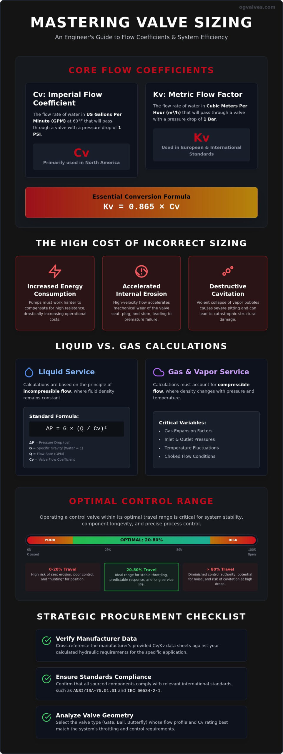
Selecting a valve based on nominal pipe diameter rather than precise fluid dynamics is a fundamental engineering error that guarantees system inefficiency. Inaccurate sizing remains a primary cause of premature component failure, excessive energy loss, and the destructive effects of cavitation in high-velocity lines. Precision in calculating pressure drop across industrial valves isn’t merely a design preference. It’s a regulatory and safety necessity for critical infrastructure. This technical guide provides the rigorous mathematical framework and engineering principles required to master Cv and Kv calculations for liquid and gas services.
You’ll gain a comprehensive understanding of the performance trade-offs between different valve geometries while ensuring strict compliance with international standards such as ANSI/ISA-75.01.01 and IEC 60534-2-1. We’ll detail the specific formulas for liquid flow, address the complexities of gas expansion factors, and define the operational margins necessary to maintain stable control within the 65 to 80 percent travel range. This analysis moves from foundational flow coefficients to the advanced parameters required for high-pressure industrial applications.
Key Takeaways
- Define the critical relationship between Imperial Flow Coefficient (Cv) and Metric Flow Factor (Kv) to maintain mathematical precision across international engineering specifications.
- Identify media-specific variables, including specific gravity and expansion factors, required for accurately calculating pressure drop across industrial valves in liquid and gas systems.
- Analyze the flow profiles of gate, ball, and butterfly valves to select the geometry that optimizes Cv ratings while meeting specific throttling requirements.
- Implement the 20-80% travel range benchmark to mitigate the risks of cavitation, seat erosion, and system instability associated with oversized components.
- Establish a technical verification protocol for manufacturer data sheets to ensure all sourced components comply with current ANSI/ISA and API standards.
Defining Valve Flow Coefficient (Cv) and Pressure Drop
The Valve Flow Coefficient (Cv) is the fundamental metric used to quantify the hydraulic capacity of a valve at specific travel positions. By definition, Cv represents the flow rate of water, measured in US gallons per minute (GPM) at 60°F, that passes through a valve with a pressure differential of exactly 1 pound per square inch (psi). This standardized value serves as the primary clinical baseline for comparing industrial valves across various manufacturers. Precision in calculating pressure drop across industrial valves allows procurement specialists and engineers to evaluate hydraulic efficiency without ambiguity. It provides a quantifiable measure of a valve’s efficiency in allowing fluid passage while identifying its inherent resistance to flow.
Accurately calculating pressure drop across industrial valves requires an understanding of the relationship between Imperial and Metric standards. While Cv is dominant in North American markets, the Metric flow factor (Kv) is the preferred unit in European and international engineering standards. Kv is defined as the flow of water in cubic meters per hour (m³/h) with a pressure drop of 1 bar. Engineers must utilize precise conversion factors to ensure system integrity: Kv = 0.865 × Cv. Failure to account for these units during the procurement phase can lead to significant sizing errors and subsequent system failure.
The Mathematical Relationship Between Flow and Pressure
Valve flow dynamics are rooted in the Bernoulli principle. As a fluid medium moves through the restricted orifice of a valve, its velocity must increase to maintain a constant mass flow rate. This acceleration converts potential energy, represented by static pressure, into kinetic energy. The resulting pressure drop (ΔP) is essentially the energy consumed by the valve to move the fluid through the restriction. This process isn’t entirely reversible. A portion of the energy is permanently lost to the system as turbulence, noise, and heat. Standardized testing protocols ensure that manufacturer-provided Cv values reflect these energy conversion rates under controlled variables.
Operational Impact of Excessive Pressure Drop
Maintaining an optimal pressure drop is critical for the long-term viability of heavy industrial systems. When a valve induces a drop that exceeds design parameters, several negative outcomes occur:
- Increased Energy Consumption: Pumping systems must compensate for high resistance, leading to significantly higher electrical costs in large-scale facilities.
- Internal Erosion: High-velocity flow through restricted paths accelerates the mechanical wear of the valve seat, plug, and stem.
- Cavitation Risks: If the local pressure drops below the fluid’s vapor pressure, vapor bubbles form and collapse violently, causing severe pitting and structural damage.
System designers must balance the need for precise control with the necessity of minimizing energy loss. A valve with an inappropriately low Cv for the required flow will act as a permanent bottleneck, compromising the total system head and downstream process stability. Every component must be verified against the calculated hydraulic requirements of the specific application.
Precision in calculating pressure drop across industrial valves requires a fundamental distinction between incompressible and compressible fluids. While liquid flow dynamics are relatively predictable, gases and vapors introduce variables that shift according to pressure and temperature fluctuations. Engineering teams must identify the specific physical properties of the medium to select the correct mathematical model and avoid significant sizing errors that lead to system instability.
Liquid Flow Calculations and Variable Analysis
Calculating pressure drop across industrial valves for liquid service relies on the relationship between flow rate, the valve’s flow coefficient, and the fluid’s specific gravity. The standard formula, ΔP = G × (Q / Cv)², assumes the fluid is incompressible and the flow remains turbulent. Specific gravity is the ratio of the density of a substance to the density of a standard reference material, typically water at 4°C for liquids, used to calibrate the fluid’s inertial resistance within a valve orifice. In heavy industrial sectors like petrochemical processing, specific gravity varies significantly with temperature, necessitating real-time data for accurate modeling.
High-viscosity liquids require additional correction factors. When processing heavy hydrocarbons or polymers, the Reynolds number may drop, indicating laminar or transitional flow rather than the turbulent flow assumed by standard Cv ratings. Engineers must apply a viscosity correction factor (Fv) to prevent underestimating the required valve size. Engineers requiring precise material classifications should consult with technical specialists to ensure selected components meet these rigorous hydraulic demands.
Managing Compressible Gas and Steam Flow
Gas and steam applications are significantly more complex because the density of the medium changes as it passes through the valve’s restriction. ANSI/ISA-75.01.01 standards define the equations required to account for this compressibility. These calculations must incorporate the expansion factor (Y) and the ratio of specific heats (Fk). As the pressure drops across the valve, the gas expands, increasing its velocity. If the pressure drop ratio (ΔP/P1) reaches a critical threshold, typically around 0.5, the fluid reaches sonic velocity.
This state is known as choked flow. Once flow is choked, further increases in the pressure differential won’t increase the mass flow rate. Sizing calculations for steam must also account for specific volume, as saturated steam behaves differently than superheated steam. Failure to account for these compressible characteristics often results in undersized valves that cannot meet peak demand or oversized valves that suffer from severe vibration and noise. Maintaining a clinical focus on these variables ensures the structural soundness of the entire pressure-containing system.
Flow Profiles Across Valve Types: Gate, Ball, and Butterfly
The internal architecture of a valve is the primary determinant of its flow coefficient. While the mathematical formulas discussed previously provide the theoretical framework, the physical geometry of the port and trim dictates the actual resistance encountered by the fluid. Full-bore industrial ball valves offer the highest Cv ratings because their internal flow path is virtually identical to the pipe diameter. This unobstructed passage minimizes turbulence and pressure loss, making them the standard for high-capacity isolation. In contrast, gate valves also provide low resistance when fully open but are susceptible to seat damage if used for flow regulation.
Globe valves prioritize control over capacity. Their high-restriction profile forces the fluid through a 90-degree turn, creating a significant pressure differential. This design is essential for precise throttling where a high pressure drop is a functional requirement rather than a system inefficiency. Butterfly valves serve as a strategic middle ground. They provide a high-capacity, space-saving alternative for large-diameter lines, though the presence of the disc in the flow stream prevents them from achieving the absolute maximum Cv seen in full-bore ball designs. Calculating pressure drop across industrial valves must account for these geometric variations to ensure the selected valve aligns with the system’s hydraulic profile.
High-Capacity Isolation vs. Throttling Precision
Valve selection requires a detailed analysis of pressure recovery factors. High-recovery valves, such as ball and butterfly types, allow the fluid pressure to recover significantly after passing the orifice. This is advantageous for isolation but increases the risk of cavitation if the vena contracta pressure drops below the vapor limit. Low-recovery valves, typically globe designs, dissipate energy more effectively through the trim, providing a more predictable control curve. V-port ball designs bridge this gap by modifying the port geometry to provide linear flow characterization, offering a higher Cv than globe valves while maintaining the precision needed for complex industrial processes.
Material Influence on Long-Term Cv Integrity
The structural composition of valve internals directly affects flow efficiency over the component’s lifecycle. Surface roughness in cast valve bodies can induce micro-turbulence, slightly reducing the initial Cv compared to precision-forged alternatives. In aggressive environments, material selection becomes a critical factor in maintaining laminar flow. Utilizing high-alloys like super duplex or Hastelloy prevents the internal erosion and pitting that would otherwise alter the trim geometry and degrade the valve’s flow coefficient over time. Precise material classification ensures that the valve’s performance remains consistent with the original engineering specifications, protecting the integrity of the entire fluid processing system.
Engineering Best Practices for Sizing and Cv Selection
Effective valve sizing demands that the calculated Cv resides within the 20 to 80 percent travel range of the selected component. This benchmark ensures the valve maintains sufficient resolution to handle process fluctuations without compromising mechanical integrity. Precision in calculating pressure drop across industrial valves prevents the operational instability associated with both oversizing and undersizing. Selecting a valve that operates too close to its seat or at its maximum travel limit leads to non-linear control response and accelerated component fatigue.
Oversized valves represent a significant risk to process stability. When a valve is too large for the application, it operates near the seat during normal flow conditions. This proximity induces high-velocity fluid jets that cause rapid seat erosion and a phenomenon known as “hunting,” where the control system oscillates as it attempts to find a stable position. Conversely, undersized valves result in excessive pressure differentials and noise. They often fail to meet peak demand requirements during process surges, acting as a permanent bottleneck in the critical infrastructure. Sizing must be integrated with the selection of industrial valve actuators to ensure that the torque or thrust output can overcome the dynamic hydraulic forces. For assistance with complex automation specifications, engineers should consult with our technical procurement team to verify actuator-to-valve compatibility.
Ensuring Control Stability and Resolution
Valve flow characteristics, such as linear or equal-percentage, dictate how the Cv changes relative to stem travel. In systems where the pressure drop across the valve decreases as flow increases, an equal-percentage characteristic is often required to maintain a stable loop gain. This mathematical relationship ensures that the control system remains responsive during both minimum and maximum flow scenarios. Maintaining pneumatic control stability requires a clinical understanding of how the Cv curve interacts with the specific travel of the valve stem under varying load conditions.
Mitigating Cavitation and Noise in High-Pressure Drops
The liquid pressure recovery factor (Fl) is a clinical metric used to assess cavitation risk during the process of calculating pressure drop across industrial valves. High-capacity valves, such as ball or butterfly types, typically have lower Fl values. This means they are more susceptible to cavitation when the pressure at the vena contracta falls below the liquid’s vapor pressure. If the pressure differential is high, vapor bubbles form and collapse violently, causing severe pitting and structural fatigue. Implementing anti-cavitation trim or multi-stage pressure reduction is a technical necessity in these high-differential applications to ensure long-term durability and regulatory adherence.
Strategic Procurement: Technical Verification of Cv
The procurement of high-pressure components requires a rigorous verification of manufacturer data to ensure operational safety. Technical data sheets often provide a nominal flow coefficient, but these values must be scrutinized against the specific service conditions identified during the process of calculating pressure drop across industrial valves. Engineers must confirm that the testing methodologies used to derive these coefficients align with ANSI/ISA-75.01.01 or IEC 60534 standards. Any discrepancy between the manufacturer’s testing media and the actual process fluid can result in significant hydraulic deviations that compromise system efficiency.
Sourcing gate valves and other isolation components from certified suppliers is a prerequisite for maintaining the integrity of the hydraulic design. This ensures that internal port dimensions and wedge geometries conform to strict dimensional tolerances. Beyond nominal sizing, technical teams must verify that Material Test Reports (MTRs) and Positive Material Identification (PMI) testing align with the flow specifications. Precise material classification is essential to prevent internal erosion, which would otherwise alter the valve’s internal geometry and invalidate the original pressure drop calculations over the component’s lifecycle.
Compliance with API and ASME Selection Standards
Verifying that selected valves meet API 600 or API 6D flow path requirements is a critical step in the procurement protocol. These standards dictate the minimum wall thicknesses and bore diameters that directly influence the valve’s capacity and structural soundness. For safety-critical lines, third-party testing serves as an essential validation of the flow coefficient. Comprehensive documentation and traceability are non-negotiable in heavy industrial sectors, as they provide the necessary audit trail to confirm that every valve in the system meets the calculated requirements for calculating pressure drop across industrial valves.
Partnering with OG VALVES LTD. for Technical Support
Specialist suppliers act as technical partners by assisting procurement specialists in matching complex Cv requirements to a localized global inventory. This expertise is particularly valuable when navigating the trade-offs between different material grades and trim designs. In critical infrastructure applications, the reliability of a global supply chain allows for the fast-track delivery of specialized components, ensuring that system performance is maintained even during unplanned maintenance intervals. A structured procurement checklist should always include the following technical variables:
- Material Classification: Compatibility with the fluid medium and temperature range.
- Regulatory Standards: Adherence to API, ASME, or ISO benchmarks.
- Dimensional Accuracy: Verification of face-to-face and bore dimensions.
- Flow Coefficient: Validation of Cv/Kv ratings against system hydraulic models.
This methodical approach to procurement ensures that the final valve selection is rooted in functional reality and long-term performance. By prioritizing technical verification over simple cost metrics, organizations protect their infrastructure from the high costs associated with component failure and energy inefficiency.
Optimizing System Integrity Through Precise Hydraulic Specification
Mastering the variables involved in calculating pressure drop across industrial valves is a prerequisite for any safety-critical infrastructure project. This technical discipline ensures that components operate within the optimal 20 to 80 percent travel range, mitigating the destructive effects of cavitation and seat erosion. Engineers must prioritize the clinical verification of flow coefficients against established API and ASME standards to maintain system efficiency and regulatory compliance over the long term. Precise modeling of liquid and gas dynamics remains the only reliable method to prevent premature mechanical failure.
Selecting the correct valve geometry and material classification requires a partner with deep technical expertise in high-pressure fluid systems. OG VALVES LTD. acts as a global supplier of API-standard industrial valves, maintaining a specialized inventory that includes Super Duplex and high-alloy components for the most aggressive environments. We provide the technical support necessary to match your specific Cv requirements with our verified global inventory. Request a Technical Quote from OG VALVES LTD. to ensure your next installation meets the highest benchmarks of engineering excellence.
Implementing these rigorous sizing principles protects your critical infrastructure from energy loss and operational instability. Reliable hydraulic performance begins with precise mathematical modeling and the sourcing of verified, high-performance components.
Frequently Asked Questions
What is the difference between Cv and Kv in valve sizing?
Cv and Kv differ primarily in their units of measurement and standardized testing conditions. Cv is an Imperial unit representing flow in US gallons per minute with a 1 psi pressure differential. Kv is the Metric equivalent, defined as flow in cubic meters per hour with a 1 bar pressure drop. The clinical conversion factor is Kv = 0.865 × Cv. Engineers must ensure unit consistency to prevent sizing errors in international projects.
How does Specific Gravity affect the pressure drop calculation?
Specific Gravity (SG) represents the ratio of a fluid’s density to that of water at 4°C. In the standard liquid flow equation, pressure drop is directly proportional to the SG of the medium. Higher SG values indicate denser fluids that require more energy to move through the valve orifice. Accurate SG data is essential when calculating pressure drop across industrial valves processing complex hydrocarbons to ensure the pump head accounts for fluid resistance.
Can I use the same formula for both liquid and gas pressure drops?
You can’t use the same formula for both media because gases are compressible fluids. Liquid calculations assume a constant density, whereas gas density changes as pressure drops through the valve. Gas formulas must incorporate expansion factors and the ratio of specific heats to account for these volumetric changes. Utilizing a liquid formula for gas applications results in significant undersizing and potential system failure under high-velocity conditions.
What are the consequences of selecting a valve with an excessively high Cv?
Selecting a valve with an excessively high Cv leads to poor control resolution and premature mechanical fatigue. The valve will operate too close to its seat during normal flow, causing high-velocity fluid jets that accelerate seat erosion. This condition also induces control system “hunting,” where the actuator constantly oscillates to maintain a setpoint. Proper sizing requires that the normal flow rate falls within the 20 to 80 percent travel range.
Why do globe valves have significantly lower Cv values than ball valves?
Globe valves utilize a tortuous, S-shaped flow path that forces the fluid through multiple 90-degree turns. This internal geometry creates high turbulence and a significant pressure differential, resulting in lower Cv values. Ball valves, specifically full-bore designs, provide a straight-through flow path with minimal obstruction. This architectural difference allows ball valves to achieve maximum hydraulic capacity for isolation, while globe valves are prioritized for precise throttling applications.
Is the Cv value constant regardless of how far the valve is open?
The Cv value isn’t constant and varies based on the valve’s opening percentage. While manufacturers provide a “rated Cv” for the fully open position, the actual flow coefficient follows an inherent flow characteristic curve as the stem travels. This curve is typically classified as linear, equal-percentage, or quick-opening. Engineers must utilize the Cv value corresponding to the specific operating point when calculating pressure drop across industrial valves at minimum or normal flow conditions.
What are the risks of ignored choked flow in gas Cv calculations?
Ignoring choked flow in gas calculations prevents the system from reaching its required mass flow rate. Once a fluid reaches sonic velocity at the valve orifice, increasing the pressure drop won’t increase the flow. This state often generates extreme noise levels and severe vibration that can lead to structural failure of the valve or downstream piping. Sizing protocols must identify the critical pressure drop ratio to avoid these destructive conditions.
How do I convert a Cv value into a flow rate in GPM?
To convert a Cv value into a flow rate in GPM, you must know the pressure drop and the fluid’s specific gravity. The standard formula is Q = Cv × √(ΔP / SG). For example, a valve with a Cv of 100 and a 4 psi pressure drop processing water will yield a flow rate of 200 GPM. This calculation provides the theoretical maximum flow for a specific valve opening and is a clinical tool for system capacity verification.
 Responsive Menu