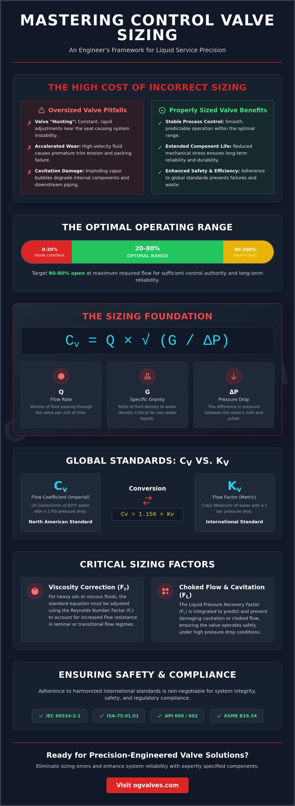
Oversizing a control valve is not a safety margin; it is a calculated risk for system instability and mechanical failure. You likely recognize the operational strain caused by valve hunting or the rapid trim degradation associated with cavitation when a component is poorly specified. These technical failures often originate from a fundamental misunderstanding of the fluid dynamics required for precise control valve sizing for liquid service. In an environment where global stainless steel melt shop production reached 64.2 million tons in early 2026, the cost of material waste and premature component replacement represents a significant industrial inefficiency.
This guide provides the rigorous analytical framework needed to master Cv calculations and ensure your equipment operates within the critical 20-80% opening range. By adhering to the verified IEC 60534-2-1:2011 standards and harmonized ISA protocols, you’ll eliminate the ambiguities that lead to premature component fatigue. We will examine the specific selection criteria for globe, butterfly, and ball valves, focusing on pressure drop variables and fluid property corrections. This methodical approach ensures that your infrastructure meets the highest benchmarks for safety and operational output as the global control valve market expands toward its projected USD 11.5 billion valuation in 2026.
Key Takeaways
- Establish a precise mathematical baseline by defining the relationship between flow rate, specific gravity, and differential pressure for non-compressible fluids.
- Apply harmonized IEC 60534-2-1 and ISA-75.01.01 equations to maintain regulatory compliance and account for pipe geometry factors.
- Predict and prevent cavitation or choked flow by integrating the Liquid Pressure Recovery Factor (Fl) into your control valve sizing for liquid service.
- Select the optimal valve body style, comparing globe and high-performance butterfly designs, based on calculated flow requirements and operational durability.
- Ensure industrial safety and adherence to global benchmarks by verifying all technical specifications against API 600, API 602, and ASME B16.34 standards.
The Engineering Fundamentals of Control Valve Sizing in Liquid Systems
Precision in industrial process control depends on the accurate sizing of the final control element to match the dynamic requirements of the system. Inadequate control valve sizing for liquid service often results in operational instability, specifically when the valve is oversized for the intended flow rate. Oversized valves operate too close to the seat, causing “hunting” where the actuator constantly adjusts to maintain a setpoint. This behavior leads to accelerated trim erosion and premature packing failure due to high-velocity fluid impingement on the internal components. It’s a common engineering error that compromises the durability of the entire process loop.
To achieve long-term reliability, technical experts must target an operating range where the valve is 60-80% open at the maximum required flow. This ensures sufficient control authority and prevents the valve from operating in the non-linear portion of its flow characteristic curve. The fundamental equation for liquid sizing relates the flow coefficient (Cv) to the flow rate (Q), specific gravity (G), and the pressure drop (ΔP) across the valve trim. This relationship defines the hydraulic capacity needed to maintain process stability without inducing mechanical stress on the valve body or downstream piping.
Flow Coefficient (Cv) vs. Flow Factor (Kv)
The Flow Coefficient (Cv) is the primary index used in North American engineering to quantify valve capacity. By definition, Cv represents the volume of water in US gallons per minute that will flow through a valve at a temperature of 60°F with a pressure drop of 1 psi across the trim. For global projects utilizing metric specifications, the Flow Factor (Kv) is the standard, representing flow in m³/h with a 1 bar pressure drop. Engineers convert between these standards using the constant 1.156, where Cv = 1.156 x Kv. This conversion is critical for maintaining consistency across international procurement chains where hardware from different regulatory regions must interface seamlessly.
The Impact of Specific Gravity on Liquid Sizing
Liquid density is a variable that directly influences the pressure-drop-to-flow ratio. In petrochemical applications, specific gravity often deviates significantly from the standard value of 1.0 assigned to water. High-temperature process fluids exhibit lower density, which requires a corresponding adjustment in the sizing calculation to avoid under-sizing the valve. If the fluid density isn’t corrected for actual operating temperatures, the resulting flow capacity will be insufficient for the process demands.
Standard Equations and Mathematical Frameworks for Liquid Flow
Adherence to global benchmarks is mandatory for high-stakes infrastructure projects. The primary international standard, IEC 60534-2-1:2011, provides the mathematical framework for industrial-process control valve sizing equations. This standard is harmonized with ANSI/ISA-75.01.01, allowing engineers to utilize either framework to achieve consistent results in control valve sizing for liquid service. These equations are designed to calculate the required flow coefficient by evaluating the fluid’s physical properties against the mechanical constraints of the piping system. Precision at this stage prevents the common error of selecting a valve based on pipe size rather than actual process requirements.
A critical component of these calculations is the determination of the flow regime. While most liquid applications involve turbulent flow, engineers must evaluate the Reynolds Number to identify if laminar or transitional flow conditions exist. If the Reynolds Number is low, typically due to high viscosity or low velocity, a Reynolds Number Factor (Fr) is applied to adjust the calculated Cv. This ensures the valve provides sufficient throughput despite the increased flow resistance. For high-pressure applications, technical experts often specify high-performance globe valves to manage these complex fluid dynamics with greater precision.
The Basic Liquid Sizing Equation
The standard equation for non-compressible, non-viscous liquid flow is defined as Cv = Q / (N1 * √(ΔP / G)). In this framework, Q represents the flow rate, G is the specific gravity at the flowing temperature, and ΔP is the pressure drop across the valve. N1 is a numerical constant that varies depending on whether Imperial or SI units are utilized. Unit consistency is a frequent point of failure in manual calculations; mixing bar with psi or m³/h with GPM without correcting the N1 constant will lead to catastrophic sizing errors. Engineers must also distinguish between the total system pressure drop and the specific pressure drop allocated to the valve, which should ideally account for 30% to 50% of the system’s dynamic losses.
Accounting for Piping Geometry and Reducers
In most industrial configurations, the control valve size is smaller than the adjacent piping. This necessitates the use of reducers and expanders, which introduce additional pressure losses not accounted for in the basic Cv equation. The Pipe Geometry Factor (Fp) is a correction coefficient that adjusts the valve’s effective capacity when installed between fittings. This factor is calculated by evaluating the resistance coefficients of the specific reducers used in the assembly. While Fp might be ignored during preliminary procurement estimates for line-size valves, it’s a vital variable for critical infrastructure where even a 5% deviation in capacity can lead to control loop instability or choked flow conditions.
Managing Non-Ideal Flow: Cavitation, Flashing, and Choked Flow
Standard flow equations assume the fluid remains in a liquid state throughout the valve body. However, high pressure differentials often cause the internal pressure to drop below the fluid’s vapor pressure at the vena contracta. When this occurs, the sizing process must move beyond simple Cv calculations to evaluate the risks of cavitation, flashing, and choked flow. Neglecting these phenomena during control valve sizing for liquid service leads to severe mechanical vibration, acoustic noise, and the rapid destruction of internal trim components. Precision in predicting these non-ideal flow conditions is mandatory for maintaining system reliability.
Cavitation involves a two-stage phase change where vapor bubbles form at the point of lowest pressure and then collapse violently as the pressure recovers downstream. This collapse generates localized pressure waves exceeding 100,000 psi, which physically pits even the most durable alloys. Flashing differs in that the downstream pressure remains below the vapor pressure, resulting in a permanent transition to a high-velocity, two-phase liquid-vapor mix. To prevent these conditions from limiting flow, engineers must calculate the maximum allowable pressure drop (ΔP max). This value represents the threshold where the flow becomes choked, and additional increases in pressure drop no longer result in an increased flow rate. Effective control valve sizing for liquid service must account for the Liquid Pressure Recovery Factor (Fl) to identify this threshold accurately.
The Liquid Pressure Recovery Factor (Fl)
The Liquid Pressure Recovery Factor (Fl) is a dimensionless coefficient that describes a valve’s ability to convert kinetic energy back into static pressure. High-recovery valves, such as butterfly valves, allow for significant pressure recovery but are highly susceptible to cavitation because the internal pressure drop is much deeper for a given total pressure loss. Conversely, globe valves are classified as low-recovery valves with higher Fl values, making them better suited for high pressure drop applications. For extreme service conditions, multi-stage trim designs are specified to artificially increase the recovery factor by dividing the total pressure drop into smaller, manageable increments that stay above the vapor pressure threshold.
Mitigating Cavitation and Flashing Damage
When process conditions make cavitation or flashing unavoidable, material selection and trim geometry become the primary lines of defense. Hardened trim materials, such as Stellite or tungsten carbide, provide the necessary surface hardness to resist the erosive impact of bubble collapse and high-velocity two-phase flow. Anti-cavitation trim designs utilize tortuous paths or perforated cages to create high-frequency, low-energy turbulence that shifts the bubble collapse away from the metal surfaces. Because flashing is a thermodynamic consequence of the system’s downstream pressure being lower than the fluid’s vapor pressure, valve design can only mitigate its erosive effects rather than prevent the phase change itself. In these scenarios, sacrificial liners and downstream pipe size increases are often required to protect the structural integrity of the piping system.
Mapping Sizing Results to Industrial Valve Selection
Precise control valve sizing for liquid service remains a theoretical exercise until the calculated Cv is mapped to a physical valve body capable of withstanding the process’s mechanical stresses. Selecting a valve based solely on the pipe diameter is a frequent cause of control loop failure. Instead, technical experts must verify that the required Cv falls within the optimal 20-80% travel range of the selected valve. Operating outside these parameters leads to poor resolution at low flow or a lack of control authority at maximum capacity. This selection phase also requires finalizing the pressure class, typically governed by ASME B16.34 or API 600, and ensuring material compatibility with the process fluid.
Finalizing the specification involves more than just hydraulic capacity. Engineers must evaluate the required end connections, whether flanged, butt-weld, or socket-weld, to ensure structural soundness at the installation point. For critical infrastructure, the body material must be selected based on corrosion resistance and temperature limits, often utilizing specialized alloys like Super Duplex or Inconel® when standard stainless steel is insufficient. For assistance in matching your technical data to a specific hardware configuration, you can view our full range of industrial valves to ensure compliance with global safety standards.
Choosing the Right Valve Body Style
Globe valves serve as the industry standard for precise throttling applications. Their internal geometry allows for high-pressure drops and the integration of anti-cavitation trims, making them ideal for high-stakes liquid control. In contrast, high-performance butterfly valves offer a cost-effective solution for high-flow, low-pressure applications where space and weight are primary constraints. For high-pressure service requiring tight shut-off and high flow capacity, trunnion-mounted ball valves provide a robust alternative, though they require careful sizing to manage the high recovery factors discussed in previous sections.
Selecting the Inherent Flow Characteristic
The inherent flow characteristic defines the relationship between the valve stroke and the flow rate at a constant pressure drop. Equal percentage trims are the default choice for most liquid control loops. This characteristic provides a constant percentage change in flow for each unit of valve travel, which compensates for the decreasing pressure drop typically seen as flow increases in a system. Linear characteristics are reserved for level control applications or systems where the pressure drop across the valve remains constant regardless of the flow rate. Quick-opening trims are generally avoided in liquid service control loops as they provide poor throttling resolution and can induce water hammer during rapid actuation.
Procurement and Technical Specification with OG VALVES
Technical verification of control valve sizing for liquid service is the final safeguard against systemic failure in high-pressure infrastructure. Theoretical calculations often fail to account for the specific manufacturing tolerances and material behaviors of industrial hardware. OG VALVES acts as a technical partner for procurement specialists, ensuring that every specified globe, ball, or butterfly valve aligns with the calculated process demands. This verification process prevents the acquisition of components that might technically meet a Cv requirement but lack the structural soundness for long-term operational output. By bridging the gap between fluid dynamics and hardware procurement, we eliminate the risks of specifying incompatible equipment for critical control loops.
Adherence to international benchmarks like API 600, API 602, and ASME B16.34 is a mandatory requirement for our global supply chain operations. These standards define the pressure-temperature ratings and minimum wall thicknesses necessary for industrial safety. To maintain high-stakes trust, every valve undergoes rigorous quality assurance protocols, including hydrostatic and pneumatic pressure testing. Positive Material Identification (PMI) testing is conducted on all high-alloy trims to verify that the chemical composition matches the technical specification. These clinical testing procedures ensure that each component functions as a dependable partner in heavy industrial sectors, particularly where the cost of failure is catastrophic.
Technical Consultation for Severe Service
In corrosive or high-temperature liquid applications, standard trim geometries are often insufficient. We collaborate with engineering teams to develop custom trim specifications, utilizing materials like Super Duplex or Monel® to resist chemical degradation. Our global inventory management system allows for the rapid replacement of failed control components, which is vital for minimizing facility downtime during unscheduled maintenance. Furthermore, we facilitate the precise integration of valve actuators into the sized control assembly. This ensures that the mechanical output of the actuator matches the torque or thrust requirements of the valve under full differential pressure conditions.
Ensuring Regulatory and Material Compliance
Maintaining a transparent audit trail is essential for regulatory adherence in the oil, gas, and power sectors. We provide comprehensive documentation for every order, including Material Test Certificates (MTCs) that verify the origin and properties of the valve body and internal components. For sour liquid service, our products strictly adhere to NACE MR0175/ISO 15156 standards to prevent sulfide stress cracking. This methodical focus on material science and regulatory benchmarks ensures that your infrastructure remains compliant with the most stringent industrial safety protocols. For a definitive specification on your next project, Contact OG VALVES for a technical quote on sized control valves.
Securing Operational Stability in High-Stakes Infrastructure
Precision in control valve sizing for liquid service is a prerequisite for maintaining the structural soundness of industrial systems. By applying the rigorous mathematical frameworks established by IEC 60534-2-1; technical experts eliminate the operational risks associated with cavitation and valve hunting. Selecting the correct valve geometry and inherent flow characteristic ensures that the component operates within its optimal travel range; preventing the premature trim degradation that often follows poor specification. This methodical approach to fluid dynamics is the primary defense against systemic failure and unmanaged fugitive emissions.
OG VALVES provides the technical expertise and global supply chain capability required to support your most demanding infrastructure projects. Every component we supply undergoes rigorous quality control; including PMI testing and pressure testing; to verify adherence to global benchmarks like API and ASME. We act as a dependable partner; delivering high-specification valves that meet the precise needs of heavy industrial sectors. Take the next step in optimizing your facility’s performance and safety. Request a Technical Quote for Industrial Control Valves to ensure your system remains resilient under extreme process conditions.
Frequently Asked Questions
What is the most common mistake in control valve sizing for liquid service?
The most frequent error in control valve sizing for liquid service is selecting a valve based on the existing pipe diameter rather than the calculated flow coefficient. This practice almost always results in an oversized valve that operates too close to its seat. Such configurations lead to control loop hunting and accelerated mechanical wear on the trim due to high-velocity fluid impingement during low-travel operation.
How do I convert between Cv and Kv for my sizing calculations?
Engineers convert between these two flow indices using the mathematical constant 1.156. The formula is defined as Cv = 1.156 x Kv; conversely, Kv = 0.865 x Cv. This conversion is essential for maintaining technical consistency in global projects where procurement specifications might fluctuate between Imperial and SI units. Accurate conversion ensures the physical hardware matches the hydraulic requirements defined in the initial engineering phase.
Why is the Liquid Pressure Recovery Factor (Fl) so important?
The Liquid Pressure Recovery Factor (Fl) is critical because it quantifies the valve’s ability to recover static pressure after the vena contracta. A low Fl indicates high pressure recovery, which significantly increases the probability of cavitation and choked flow. Identifying this factor during the sizing process allows technical experts to select a valve style that maintains internal pressures above the fluid’s vapor pressure threshold.
Can I use a butterfly valve for high-pressure drop liquid service?
High-performance butterfly valves are generally unsuitable for high-pressure drop liquid service because of their high-recovery characteristics. These valves exhibit low Fl values, which frequently lead to cavitation when the differential pressure is significant. For high-stakes applications involving substantial pressure drops, globe valves are the preferred selection; their internal geometry allows for lower pressure recovery and more stable throttling under stress.
What is the difference between cavitation and flashing in a control valve?
The primary difference lies in the downstream pressure relative to the fluid’s vapor pressure. In cavitation, vapor bubbles form at the vena contracta and collapse as pressure recovers downstream, causing mechanical pitting. In flashing, the downstream pressure remains below the vapor pressure, resulting in a permanent two-phase liquid-vapor flow. While trim design can mitigate cavitation, flashing is a thermodynamic outcome that requires material hardening.
How does fluid viscosity affect the required valve size?
High fluid viscosity increases the resistance to flow and necessitates a larger valve size to achieve the target throughput. Standard sizing equations assume turbulent flow; however, viscous fluids often exhibit laminar or transitional flow regimes. Engineers must apply a viscosity correction factor based on the Reynolds number calculation to adjust the required Cv. This ensures the valve provides sufficient capacity for heavy oils or other non-Newtonian fluids.
What flow characteristic should I choose for a liquid level control loop?
A linear flow characteristic is the standard selection for liquid level control loops where the pressure drop across the valve remains relatively constant. This provides a direct, proportional relationship between the valve stroke and the flow rate, ensuring stable process gain. While equal percentage trims are common in pressure control, the linear characteristic simplifies the tuning of level controllers in most industrial tank and vessel applications.
How does the pipe geometry factor (Fp) impact my valve selection?
The pipe geometry factor (Fp) accounts for the additional pressure losses introduced by reducers and expanders when the valve size is smaller than the line size. This factor reduces the effective capacity of the valve-plus-fitting assembly. Neglecting Fp in control valve sizing for liquid service can lead to an under-sized configuration that fails to meet maximum flow requirements once installed in the actual piping system.
 Responsive Menu