Globe Valve Throttling: A Technical Guide to Flow Regulation and Performance
March 25, 2026
Home+Globe Valve Throttling: A Technical Guide to Flow Regulation and Performance
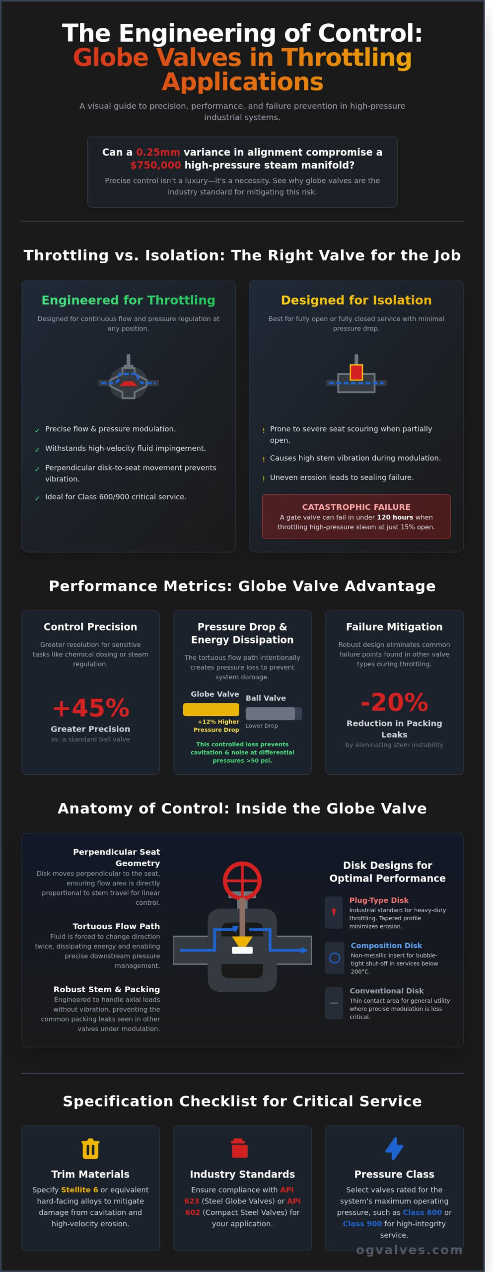
Can a 0.25 millimeter variance in seat-to-disk alignment compromise the operational integrity of a $750,000 high-pressure steam manifold? Engineers in the oil and gas sector understand that maintaining precise control under high-differential pressure is a constant battle against physical degradation. While many gate or ball valves fail under continuous modulation, globe valve throttling remains the industry standard due to its unique linear stroke and flow-path geometry. Industry data confirms that premature seat erosion and stem vibration aren’t just maintenance nuisances; they’re precursors to catastrophic system failure.
This technical guide delivers an authoritative analysis of the seat-to-disk relationship and the mechanical principles that ensure long-term performance. We’ll provide the data necessary to mitigate cavitation through specific material grades like Stellite 6 and identify the exact API 623 or API 602 specifications required for your application. We’ll conclude with a rigorous look at how to eliminate the 20% increase in packing leaks often caused by stem instability during high-velocity flow regulation.
Key Takeaways
Understand the engineering principles that make globe valves the industry standard for precise flow regulation and pressure control.
Analyze the mechanical advantage of perpendicular seat geometry and its role in maintaining linear flow characteristics under varying conditions.
Identify critical failure modes such as cavitation and erosion during globe valve throttling and learn the necessary protocols to mitigate damage.
Review the essential selection criteria and compliance requirements for API 623 and API 602 standards in high-pressure industrial environments.
Learn how to specify optimal trim and body materials to ensure the structural integrity and long-term performance of valves in critical service.
Defining Flow Regulation and the Throttling Capability of Globe Valves
Throttling is the intentional regulation of fluid flow and pressure by varying the position of the valve closure member. Globe valve throttling is the process of controlling flow velocity and pressure drop via a movable disk and stationary ring. Standard engineering protocols prioritize this valve type for systems requiring consistent flow modulation due to its robust internal architecture. This Globe valve overview outlines the essential design features that allow these components to withstand high-velocity fluid impingement. Unlike isolation valves, globe valves maintain structural integrity when the plug is positioned close to the seat for extended periods. They’re essential for maintaining system stability in Class 600 or Class 900 service where precise pressure management is mandatory for safety and process integrity.
Throttling vs. Isolation: Key Functional Differences
Isolation valves like gate or ball types focus on achieving minimal pressure drop in the fully open position. They don’t perform well at intermediate settings. Using a gate valve for throttling at a 15% opening often results in severe seat scouring and stem vibration. These forces can compromise the seal within 120 hours of operation under high-pressure steam conditions. Globe valves are specifically engineered to operate at intermediate positions without mechanical degradation. Their design allows the plug to move parallel to the flow stream, which minimizes lateral stress on the stem and ensures long-term performance in demanding industrial environments. When bubble-tight isolation is the primary requirement rather than throttling, engineers often evaluate alternatives such as the triple offset butterfly valve, which eliminates friction-induced seat wear through its unique geometric design.
The Role of Pressure Drop in Flow Control
Globe valves utilize a tortuous flow path to dissipate energy and control downstream pressure. As fluid enters the valve body, it’s forced to change direction twice, creating a predictable relationship between valve lift and the flow coefficient (Cv). While this design provides superior control resolution, it results in a higher permanent pressure loss. In a typical ASME B16.34 Class 300 system, a globe valve might exhibit a 12% higher pressure drop than a ball valve, yet it offers 45% greater precision for sensitive chemical dosing or steam regulation tasks. This controlled energy dissipation prevents cavitation and noise in systems operating at differential pressures exceeding 50 psi.
The Mechanical Advantage: Seat Geometry and Linear Flow Characteristics
The mechanical superiority of the globe valve in throttling services stems from its fundamental internal configuration. Gate valves slide across the flow stream. Globe valve disks move perpendicular to the seat. This vertical alignment ensures the flow area changes in direct proportion to the stem travel. This geometry facilitates precise control over fluid velocity and pressure drop. The inherent symmetry of the seat ring and disk allows for uniform fluid distribution. This prevents the uneven erosion patterns often observed in asymmetric throttling components like butterfly valve discs or ball valve ports.
Engineers select specific disk profiles to match the required flow characteristic. A linear flow characteristic provides a flow rate directly proportional to the valve stroke; at 50% open, the flow is 50% of maximum. In contrast, an equal percentage characteristic produces a change in flow that is proportional to the flow rate just before the change. According to the Valve Selection Handbook, these geometric variations are critical for system stability in complex industrial loops. Proper selection minimizes hunting in automated control systems and ensures 100% repeatability in flow modulation.
Disk Designs: Conventional, Composition, and Plug Type
Plug-type disks represent the industrial standard for heavy-duty globe valve throttling. Their long, tapered profile provides a wider seating surface, which effectively minimizes the effects of high-velocity erosion and wire-drawing. Composition disks utilize non-metallic inserts to achieve bubble-tight shut-off in systems operating below 200°C. Conventional disks, featuring a thin contact area, serve general utility functions where precise modulation is less critical than simple isolation. For projects requiring high-integrity components, reviewing technical specifications for specific pressure classes is essential.
The Flow-Under-Seat vs. Flow-Over-Seat Dynamics
Standard installations favor flow-under-seat configurations. This orientation protects the stem packing from constant pressure and allows for easier manual operation. However, high-pressure steam systems often utilize flow-over-seat designs. This assists in closing the valve and eliminates stem vibration caused by fluctuating pressures. The direction of flow significantly impacts the mechanical integrity of the stem-to-disk connection. Incorrect orientation in high-differential pressure environments can lead to fatigue failure or separation of the disk from the stem during 100% duty cycles.
Engineering Challenges: Cavitation, Erosion, and Pressure Drops
High-velocity flow during globe valve throttling creates significant localized pressure drops. When the static pressure falls below the liquid’s vapor pressure, vapor cavities form. As these bubbles move into regions of higher pressure downstream, they implode violently. This implosion generates localized shockwaves reaching 1,000 MPa, causing mechanical pitting on the disk and seat. Erosion-corrosion occurs when high-speed particulates or droplets strike these surfaces, a phenomenon known as wire-drawing. This process can degrade a Class IV leakage rating to a total failure within 500 hours of continuous high-velocity service. Mechanical consequences include:
Vibration: High differential pressures induce mechanical resonance that can loosen fasteners and damage internal guides.
Acoustic Fatigue: Sound levels often exceed 85 dBA, indicating energy dissipation that stresses the valve body integrity.
Thermal Stress: Rapid pressure changes result in temperature fluctuations that affect material expansion rates.
Identifying and Mitigating Cavitation
Engineers identify cavitation by a distinct sound resembling gravel passing through the pipe. This acoustic energy often correlates with vibration frequencies between 500 Hz and 2,500 Hz. To mitigate these forces, OG VALVES LTD. recommends multi-stage trim designs. These components divide the total pressure drop into 3 or 4 smaller increments. This ensures the fluid pressure remains above the vapor threshold at every stage. We utilize material hardening techniques, such as applying Stellite 6 overlays to the seating surfaces, to increase impact resistance against bubble collapse. These alloys provide a Rockwell C hardness of 40 to 45, which is essential for surviving the micro-jets produced during cavitation.
The Limits of Manual Globe Valves for Throttling
Manual globe valves built to API 623 standards provide robust isolation but face limitations in precision globe valve throttling. Handwheels lack the resolution for fine adjustments; a mere 5-degree turn can result in flow fluctuations of 12% or more in high-pressure systems. Frequent manual adjustment leads to “stem-pumping.” This repeated axial movement accelerates packing wear and increases the risk of fugitive emissions beyond ISO 15848-1 allowable limits. If an application requires more than 15 adjustments per work shift, operators shouldn’t rely on manual intervention. Transitioning to an automated control valve is necessary at this stage. These systems utilize digital positioners to maintain stable flow rates within a 1% margin of error, protecting the valve’s long-term mechanical integrity.
Selection Criteria for Throttling Globe Valves: Materials and Standards
Engineering a globe valve throttling system requires strict adherence to international standards to ensure long-term operational integrity. For heavy industrial service involving larger diameters, API Standard 623 provides the necessary framework for cast steel globe valves. This standard addresses historical failure points by specifying thicker stems and more robust seat attachments than previous iterations. In smaller, high-pressure applications, API 602 governs forged steel specifications, ensuring the valve body withstands the mechanical stresses of continuous flow modulation. Material selection isn’t a static choice; it’s a technical calculation based on process fluid chemistry and the thermal cycles of the system.
Engineers must evaluate the potential for thermal expansion and contraction, which can lead to seat leaking or stem binding if materials aren’t matched correctly. The integrity of the pressure boundary depends on selecting alloys that maintain their mechanical properties at peak operating temperatures. This precision is what separates a standard isolation valve from a high-performance throttling component. In applications where zero-leakage isolation under extreme thermal cycling is the overriding concern, a triple offset butterfly valve engineered to API 609 and ASME B16.34 specifications may serve as a complementary solution within the same pipeline system.
Hard-Facing and Trim Materials
Selecting the correct trim is the primary factor in preventing premature failure. For high-velocity globe valve throttling, seat and disk surfaces frequently utilize Stellite, a cobalt-base alloy, to prevent galling and erosion. While 13% Chrome (Trim 1) remains a baseline for many applications, 316 Stainless Steel is required for corrosive environments. Throttling service demands a minimum hardness differential between seating surfaces to prevent “wire-drawing,” where high-pressure fluid carves channels across the seat face during low-flow conditions.
Compliance with ASME B16.34 and API 623
ASME B16.34 defines the pressure-temperature ratings and minimum wall thickness requirements essential for maintaining pressure boundary integrity. API 623 builds upon this by mandating larger stem diameters to resist the high torque loads required for precise adjustments. Quality assurance protocols must include Positive Material Identification (PMI) to verify that the alloy composition matches the design specification. This rigorous verification eliminates the risk of accidental material substitution in critical high-pressure systems. We provide fully documented API-compliant globe valves designed for these exact industrial specifications.
Procuring High-Performance Globe Valves for Critical Industrial Throttling
OG VALVES LTD. provides high-specification flow control solutions for the oil, gas, and power generation sectors. We prioritize engineering integrity in every procurement cycle. Effective globe valve throttling depends on the precise selection of trim configurations and body materials to manage specific pressure differentials. Our technical team provides data-backed support to identify the correct parabolic or V-port trims that mitigate cavitation and erosion. We adhere to ASME B16.34 and API 623 standards to ensure structural durability across pressure classes from 150 to 2500. Our global logistics infrastructure enables fast-track delivery for both MRO requirements and complex project schedules. Every valve is subjected to rigorous testing protocols; this includes API 598 pressure tests and ISO 15848-1 fugitive emission certifications. We ensure 100% compliance with international safety mandates to protect your facility’s operational uptime.
Custom Specifications for Heavy Industry
We engineer valves for the most demanding environments. This includes cryogenic service operating at -196°C or high-temperature steam applications reaching 540°C. Our technical headquarters in Antrim, Northern Ireland, supports global infrastructure by providing specialized material grades like Duplex, Super Duplex, or Monel. We maintain a 97% accuracy rate in logistical scheduling. This precision is vital for minimizing downtime in corrosive hydrocarbon environments. Our supply chain management focuses on providing traceable, high-integrity components that withstand extreme thermal cycling. Whether you’re sourcing for a refinery expansion or a power plant overhaul, we deliver valves that meet the exact metallurgical requirements of your process media.
Next Steps: Technical Consultation and Quotes
Precise globe valve throttling starts with accurate flow data. To receive a technical sizing evaluation, you’ll need to provide the required flow coefficient (Cv), inlet pressure (P1), and downstream pressure (P2) requirements. Our inventory includes a comprehensive range of gate, globe, and check valves available for immediate dispatch from our regional hubs. You can access our engineering team for bespoke design modifications or API 624 low-emission packing certifications. It’s our standard to provide detailed quotations and technical data sheets within 24 hours of a request. Contact us to discuss your specific flow control challenges and secure a partner committed to industrial excellence.
Securing System Integrity Through Precision Flow Regulation
Achieving reliable globe valve throttling demands a clinical focus on seat geometry and material durability to mitigate the risks of cavitation and erosion. Engineering teams must prioritize components that adhere strictly to API 623 and ASME B16.34 standards to ensure operational safety in high pressure environments. Our inventory features these certified specifications; they’re designed for the most rigorous industrial applications. We maintain a comprehensive stock of Grade F22 and F316 valves at our Northern Ireland hub to facilitate 48 hour fast track global delivery for critical projects. You’ll benefit from our specialist technical support that bridges the gap between complex engineering requirements and functional reality. It’s essential to select valves that offer quantifiable performance and long term integrity under stress. We ensure 100% of our units meet rigorous quality protocols before shipment. Consult with our technical experts for your high-performance globe valve requirements to secure your infrastructure’s future. We’re ready to help you achieve peak performance.
Frequently Asked Questions
Can any globe valve be used for throttling?
Not every globe valve is suitable for throttling service; only those with specific plug designs like parabolic or needle-shaped discs provide the necessary flow control. Standard flat-seated discs don’t survive long when held in a partially open position due to seat erosion. For precise globe valve throttling, engineers specify contoured plugs to ensure a linear or equal percentage flow characteristic. This prevents the 15% to 20% turbulence increase common in non-throttling designs.
What is the main disadvantage of using a globe valve for throttling?
High pressure drop across the valve body remains the primary disadvantage of using a globe valve for throttling applications. The S-shaped flow path forces fluid to change direction twice, resulting in a head loss coefficient that can reach 5.0 to 10.0. This internal resistance necessitates higher pumping power. It also increases the risk of noise levels exceeding 85 decibels in high-velocity gas systems, requiring additional acoustic insulation for safety compliance.
How do I prevent cavitation in a throttling globe valve?
Preventing cavitation requires maintaining the downstream pressure above the fluid’s vapor pressure through the use of multi-stage trim or anti-cavitation cages. These components divide the flow into smaller streams, increasing the pressure recovery factor from 0.5 to 0.9. If the pressure drop ratio exceeds 0.6, cavitation is likely. Installing the valve in a vertical orientation or using hardened materials like Stellite 6 helps mitigate the impact of collapsing vapor bubbles.
What is the difference between a globe valve and a needle valve for throttling?
The primary difference lies in the orifice size and the precision of flow regulation. Needle valves utilize a slender, tapered point for fine control in small-diameter lines, typically under 2 inches. Globe valves handle higher flow volumes in pipelines up to 24 inches. While a globe valve manages bulk flow, a needle valve provides a 0.01% incremental adjustment capability. It’s the standard choice for instrumentation and sampling systems where precision is paramount.
Why is the API 623 standard important for globe valves?
The API 623 standard establishes rigorous design requirements for steel globe valves to prevent stem nut failure and disc detachment. It mandates thicker stems and heavier-duty connections than the previous API 600 or ASME B16.34 standards. Compliance with API 623 ensures the valve can withstand the high-cycle fatigue of throttling service. This standard reduces the probability of catastrophic failure in 900# and 1500# pressure classes by ensuring mechanical integrity under stress.
What happens if a gate valve is used for throttling instead of a globe valve?
Using a gate valve for throttling causes severe vibration and wire-drawing erosion across the seating surfaces. Gate valves are designed for 100% open or closed positions; partial opening exposes the wedge to high-velocity flow. This results in a 40% loss of sealing integrity within 500 operating hours. The turbulent flow also induces mechanical stress that can snap the stem or damage the guide rails, leading to total valve failure.
How does flow direction (over or under seat) affect throttling performance?
Flow direction dictates the ease of operation and the stability of the valve plug during globe valve throttling. Flow-under-the-seat assists in opening the valve and protects the packing from constant pressure. Flow-over-the-seat is required for high-pressure steam to ensure tight shutoff and prevent chatter. You shouldn’t ignore these specifications, as the wrong direction increases required actuator torque by 30% or causes uncontrollable oscillations that damage the internal trim.
What are the best trim materials for high-pressure throttling service?
Hardened alloys like Stellite 6 and 410 Stainless Steel are the industry standards for high-pressure throttling trim. For severe service involving abrasive particles, tungsten carbide inserts provide a 5x increase in service life compared to standard 316 Stainless Steel. These materials maintain a hardness rating above 40 HRC. This durability is essential when differential pressures exceed 1,000 PSI to prevent rapid material loss and ensure the valve maintains its shutoff rating.
 Responsive Menu