Industrial Gate Valve Sizing: A Technical Selection Checklist for Engineers
April 13, 2026
Home+Industrial Gate Valve Sizing: A Technical Selection Checklist for Engineers
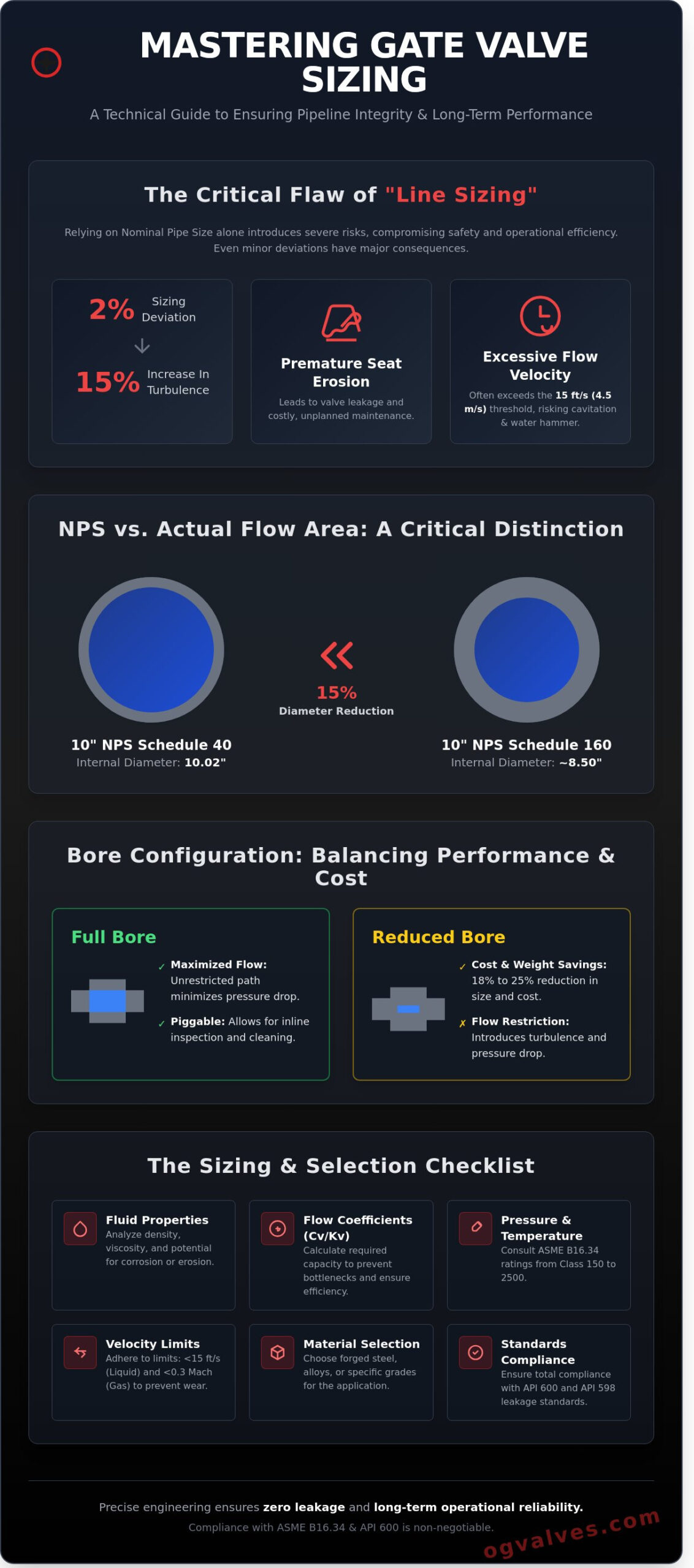
A single 2% deviation in gate valve sizing can trigger a 15% increase in localized turbulence, leading to premature seat erosion and system-wide pressure drops within the first 12 months of high-pressure service. You recognize that in critical infrastructure, the margin for engineering error is non-existent. A valve that doesn’t align perfectly with process parameters isn’t just an underperforming component; it’s a liability that compromises the safety and integrity of the entire pipeline. Relying on nominal pipe size alone often results in excessive flow velocities that exceed the 15 feet per second threshold for liquid service.
This technical checklist enables you to master the complex variables of gate valve sizing to ensure full compliance with ASME B16.34 and API 600 standards. You’ll gain a methodical framework for calculating flow coefficients and selecting specific material grades, such as forged steel for cryogenic applications or high-integrity alloys for corrosive environments. We provide a structured analysis of pressure-temperature ratings and flow velocity limits to guarantee zero leakage and long-term operational reliability. This guide moves from fundamental fluid dynamics to the rigorous quality assurance protocols required for industrial excellence.
Key Takeaways
Identify the technical risks associated with “line sizing” and learn how accurate gate valve sizing ensures long-term pressure integrity in high-stakes environments.
Analyze critical fluid properties and flow coefficients (Cv/Kv) to maintain precise flow capacity and prevent operational inefficiencies.
Master ASME B16.34 pressure-temperature ratings to select material grades capable of withstanding extreme fluctuations from Class 150 to 2500.
Implement a rigorous technical checklist to audit specifications and ensure total compliance with international engineering standards before procurement.
Discover how to leverage specialized engineering expertise for the delivery of high-spec components across global industrial supply chains.
Fundamentals of Gate Valve Sizing: Beyond Nominal Pipe Size (NPS)
Engineering a pipeline requires more than a simple correlation between pipe diameter and valve selection. Effective gate valve sizing represents a rigorous calculation of flow capacity against the structural pressure integrity of the unit. A common error in procurement is “line sizing,” where the valve’s nominal size is matched directly to the pipe’s outer diameter without evaluating internal fluid dynamics. This oversight leads to excessive flow velocities, accelerated erosion of the seating surfaces, and catastrophic pressure surges.
A Gate valve functions primarily as an isolation component; however, its internal geometry dictates the system’s hydraulic efficiency. International standards such as API 600 and ASME B16.34 define the dimensional envelopes and wall thicknesses required to maintain safety under specific pressure-temperature ratings. Engineers must calculate the Cv (flow coefficient) to ensure the valve doesn’t become a bottleneck or a source of turbulence.
Nominal Pipe Size vs. Actual Flow Area
The Nominal Pipe Size (NPS) and Diamètre Nominal (DN) are dimensionless designators. They don’t represent the actual internal diameter (ID) of the flow path. The ID is determined by the pipe Schedule, which defines the wall thickness. For instance, a 10-inch NPS pipe with a Schedule 160 wall thickness has an internal diameter of approximately 8.5 inches, while a Schedule 40 pipe has an ID of 10.02 inches. This 15% reduction in diameter significantly increases flow velocity and pressure drop. Precise gate valve sizing requires calculating the actual cross-sectional area based on the specific pipe schedule to model fluid behavior accurately.
The Impact of Bore Design on System Performance
Bore configuration is a critical variable in industrial valve specification. Full bore gate valves provide an internal diameter that matches the pipe’s bore. This design is essential for applications requiring piggability for cleaning or inspection and when minimizing pressure drop is a priority. In contrast, reduced bore valves have a smaller internal opening, typically one or two sizes smaller than the NPS. While reduced bore units offer an 18% to 25% reduction in weight and cost, they introduce flow restrictions. Transitioning between bore sizes within a single infrastructure demands careful analysis of turbulence at the seat interface to prevent cavitation and vibration-induced fatigue in high-pressure gas or liquid services. Understanding the fundamental engineering differences in a gate valve vs ball valve comparison is essential when evaluating bore design trade-offs for specific pipeline applications.
Critical Parameters for Accurate Sizing Calculations
Precision in gate valve sizing ensures long-term system integrity and prevents premature component failure. Engineers must analyze fluid density and viscosity to determine the Reynolds number, which dictates the flow regime within the pipeline. For liquid service, density directly impacts the pressure differential across the valve seat. In gas applications, compressibility factors and temperature-dependent density variations require strict adherence to ASME PTC 19.5 standards to maintain calculation accuracy.
The Flow Coefficient (Cv) represents the volume of 60°F water in gallons per minute that flows through a valve with a 1 psi pressure drop. Its metric equivalent, Flow Factor (Kv), utilizes m³/h at a 1 bar drop. Technical mastery of control valve sizing and selection principles allows for the precise determination of these values, ensuring the valve doesn’t introduce unnecessary resistance. Operational stability depends on establishing a clear range between the maximum surge flow and the minimum sustained flow rate to avoid stagnant zones or turbulence.
Fluid Velocity Limits and Erosion Control
High fluid velocity accelerates mechanical wear on the wedge and seat materials. For liquid media, maintaining velocity below 4.5 meters per second (15 feet per second) minimizes the risk of cavitation and water hammer. Gas flows shouldn’t exceed 0.3 Mach to prevent acoustic vibration and structural fatigue. Rigid adherence to these limits preserves the integrity of forged steel and alloy components in high-pressure environments. When velocities exceed these benchmarks, the resulting erosion can compromise the valve’s API 598 leakage standards within months of commissioning. A thorough understanding of gate valve failure modes caused by excessive velocity, including seat scoring and stem packing degradation, is essential for specifying the correct trim materials and maintenance intervals.
Calculating Pressure Drop and System Head Loss
The Darcy-Weisbach equation provides the mathematical framework for calculating head loss across the valve body. Engineers use the resistance coefficient (K) to quantify the energy loss attributed to specific valve geometry. A standard full-bore gate valve typically exhibits a K-factor between 0.1 and 0.2, representing minimal resistance compared to globe or butterfly configurations. Excessive pressure drop forces downstream pumps to operate outside their preferred operating range, reducing overall plant efficiency by up to 12% in poorly specified systems. For projects requiring high-specification components, reviewing industrial valve data sheets provides the necessary K-factor values for precise hydraulic modeling and pump selection.
Pressure-Temperature Ratings and Material Compliance
ASME B16.34 serves as the definitive technical framework for determining the pressure-temperature ratings of flanged, threaded, and welding-end valves. For engineers, gate valve sizing requires a precise alignment between the system’s maximum operating temperature and the allowable working pressure. As process temperatures rise, the mechanical strength of the valve body material diminishes, which often necessitates a higher pressure class to maintain structural integrity. This relationship ensures that the valve housing can withstand internal stresses without yielding or compromising the primary seal.
API 600 and API 603 standards further refine these requirements by establishing dimensional benchmarks for heavy-duty and corrosion-resistant gate valves. API 600 specifies thicker wall sections for carbon and alloy steel valves to provide a robust corrosion allowance in harsh refinery environments. Conversely, API 603 targets stainless steel and nickel-alloy valves where the chemical resistance of the material allows for a more streamlined profile. Selection between these standards depends on the fluid’s corrosivity and the expected service life of the infrastructure. Engineers evaluating isolation valve options for petrochemical service should also review the gate valve vs ball valve industrial selection criteria to determine which sealing mechanism best addresses fugitive emissions requirements under API 6D compliance.
Navigating ASME Pressure Classes
Pressure classes, ranging from Class 150 to Class 2500, define the relationship between wall thickness and pressure containment. Engineers must determine the correct class based on the Maximum Allowable Working Pressure (MAWP) at the peak operating temperature. For instance, a Class 300 carbon steel valve provides an MAWP of 740 psig at 100°F, but this rating falls to 410 psig if the temperature reaches 800°F. These ratings are standardized across flange dimensions to ensure that bolt patterns and face diameters remain consistent within a specific class, regardless of the manufacturer.
Material Influence on Dimensional Stability
Material selection is a primary constraint in gate valve sizing, particularly when dealing with cryogenic or high-heat applications. While cast iron is suitable for low-pressure water treatment, high-stakes oil and gas operations require forged steel (ASTM A105) or cast steel (ASTM A216 WCB) to handle extreme transients. Thermal expansion in large-diameter valves can lead to mechanical binding or seat leakage if the material’s expansion coefficient isn’t accounted for during the design phase.
Engineers must calculate the gate valve thrust requirements to ensure the chosen actuator can overcome the combined forces of friction and fluid pressure under these thermal loads. In critical infrastructure, Positive Material Identification (PMI) is utilized to verify that the alloy composition matches the design specification. This rigorous verification process prevents the installation of sub-standard components that could fail under the intense pressures of Class 900 or Class 1500 service.
The Industrial Gate Valve Sizing & Selection Checklist
Engineers must execute a rigorous verification protocol before procurement to mitigate risks of mechanical failure or system inefficiency. Technical data sheets must account for every operational variable to ensure the gate valve sizing aligns with the hydraulic requirements of the system. Failure to align valve specifications with actual line conditions results in accelerated seat wear or catastrophic pressure boundary failure. This checklist serves as the final technical gate before procurement documentation is finalized.
Operational Data Verification
Step 1: Confirm maximum and minimum operating pressure and temperature. Pressure and temperature ratings must comply with ASME B16.34 standards. A valve rated for 102 bar at 38°C may only be rated for 72 bar at 400°C. Engineers must verify that the selected material grade maintains its integrity at the upper thermal limit of the process.
Step 2: Define fluid characteristics and chemical compatibility. Media containing abrasive particulates or corrosive agents require specific trim materials. For instance, NACE MR0175 compliance is mandatory for sour gas environments where hydrogen sulfide levels exceed 0.05 psi partial pressure.
Step 3: Specify required flow rate and allowable pressure drop. If the allowable pressure drop is restricted to less than 0.1 bar, the internal port diameter must be verified against the piping schedule. Gate valves typically offer low resistance, but internal turbulence can still occur if the bore is restricted.
Mechanical and Compliance Specification
Step 4: Select valve type based on media. Flexible wedge gates provide reliable shut-off in steam applications. Slab gates are the standard for piggable midstream pipelines, and knife gate valves are reserved for slurries with solids content exceeding 5%.
Step 5: Identify required certifications. Industrial projects often demand API 600 for heavy-wall steel valves or API 6D for pipeline service. Verification of ISO 10434 or MSS SP-60 compliance ensures the valve meets global safety benchmarks.
Step 6: Determine actuation and end connections. Manual gear operators are sufficient for infrequent cycling, but high-torque applications or remote safety systems require pneumatic or electric actuators. End connections must match the piping system, whether flanged per ASME B16.5, socket weld, or butt weld per ASME B16.25.
Accuracy in gate valve sizing prevents the high costs of downtime and mid-project retrofitting. It’s essential that procurement teams don’t overlook the technical nuances of seat leakage rates, which should be specified according to API 598 or ISO 5208 standards. This clinical approach to selection guarantees that the valve performs as a reliable safety barrier throughout its service life. Engineers should also consult a detailed technical analysis of industrial gate valve failure modes and mitigation strategies to ensure that material compatibility and pressure differential specifications are aligned with long-term ASME B16.34 compliance requirements.
Review our technical specifications for industrial gate valves to ensure your project meets API 600 and NACE compliance standards.
Procuring Precision-Engineered Gate Valves from OG Valves
OG Valves provides the engineering depth required to transition from theoretical gate valve sizing to operational deployment. Precision in flow control demands more than just a dimensional match. It requires a verified alignment between system hydraulics and valve metallurgy. Our technical team evaluates every specification to ensure that the selected component maintains pressure integrity under maximum surge conditions. We maintain a comprehensive inventory of gate valves across all primary pressure classes, from Class 150 to Class 2500. This inventory includes materials such as A216 WCB carbon steel, A351 CF8M stainless steel, and specialized alloys for cryogenic or high-temperature service.
Our commitment to industrial safety is reflected in our zero-failure performance record. We don’t accept compromises in component quality. Every valve in our stock adheres to rigorous international standards, including API 600 and ASME B16.34. This clinical focus on engineering excellence ensures that the valves you procure will perform reliably in high-stakes environments like oil refineries, gas processing plants, and municipal water treatment facilities.
Technical Support and Specification Review
Our engineers don’t simply process orders; they perform a critical audit of your data sheets and sizing calculations to prevent procurement errors. Accurate gate valve sizing prevents issues like cavitation or premature seat wear caused by improper flow velocity. By verifying parameters such as the flow coefficient (Cv) and pressure drop against your specific application data, we ensure minimal downtime for your facility. Our team identifies potential discrepancies in material compatibility or pressure-temperature ratings before the valve reaches the site. For a deeper analysis of design standards and material selection, consult our A Technical Guide to Industrial Gate Valves.
Global Logistics and Fast-Track Supply
Infrastructure projects in the energy and utility sectors require strict adherence to delivery schedules. OG Valves manages a robust global supply chain capable of delivering large-bore gate valves, ranging from 24 to 60 inches, to international sites with minimal lead times. We utilize established logistics networks to move high-spec components while maintaining rigorous quality control protocols. Every unit undergoes hydrostatic and pneumatic testing according to API 598 standards before it leaves our facility. This commitment to project integrity protects your timeline and your budget. You can Request a technical quote for your gate valve requirements today to secure your project assets with an established global partner.
Achieve Operational Integrity with Standardized Selection
Achieving mechanical integrity in high-pressure systems requires more than matching nominal pipe diameters. Engineers must prioritize flow velocity limits and pressure drop coefficients to prevent premature seat wear or cavitation. Adherence to API 600 and ASME B16.34 standards ensures that material thickness and pressure-temperature ratings meet the rigorous demands of oil and gas infrastructure. Precise gate valve sizing eliminates the operational risks associated with under-specified components in critical flow paths.
OG Valves maintains an extensive inventory of API 600 and ASME B16.34 compliant stock to support critical project timelines and safety protocols. As specialists in heavy industrial valve supply, we provide the technical documentation and material traceability required for complex global procurement. Our global fast-track delivery network ensures that high-specification components reach your facility without administrative delays or logistics bottlenecks. Utilizing standardized checklists during the selection phase prevents costly retrofits and ensures long-term performance in the field.
What is the difference between NPS and actual bore size in gate valves?
NPS refers to the nominal pipe size, while actual bore size is the internal diameter through which the media flows. In reduced bore gate valves, the internal diameter’s typically one size smaller than the NPS designation. For example, a 4-inch NPS valve might feature a 3-inch bore. Accurate gate valve sizing requires checking the manufacturer’s specification sheet against ASME B16.34 standards to ensure flow requirements are met.
Can I use a gate valve for throttling if I size it correctly?
You shouldn’t use a gate valve for throttling regardless of sizing accuracy. Gate valves are designed exclusively for on-off service. Operating a gate valve in a partially open position causes high-velocity flow to induce vibration and seat erosion. This damage often occurs within 500 hours of operation in high-pressure systems. Engineers must specify globe or needle valves for flow regulation to maintain system integrity.
How does API 600 influence the sizing of steel gate valves?
API 600 dictates the minimum wall thickness and stem diameters for heavy-duty steel gate valves. It provides a standardized framework for gate valve sizing to ensure structural integrity under extreme mechanical stress. The standard requires a 10% thicker wall than ASME B16.34 in certain pressure classes. Compliance with API 600 ensures that the valve body can withstand the 1.5 times rated working pressure required during hydrostatic shell testing.
What happens if a gate valve is oversized for the application?
How do I calculate the Cv value for a gate valve?
You calculate the Cv value using the formula Cv = Q * sqrt(SG / ΔP), where Q is flow rate in gallons per minute, SG is specific gravity, and ΔP is pressure drop in psi. For a fully open gate valve, the Cv’s significantly higher than other valve types due to the straight-through flow path. Engineers should reference manufacturer data for the specific valve model, as the internal geometry affects the flow coefficient.
What are the most common sizing mistakes in high-pressure systems?
The most frequent error’s failing to account for the pressure-temperature derating specified in ASME B16.34. Engineers often select a valve based on its ambient temperature rating, but a Class 600 valve rated for 1480 psi at 100°F drops to 825 psi at 800°F. Another mistake is ignoring the bypass valve requirement for sizes above 10 inches in high-differential pressure applications to equalize pressure before opening.
Is a full bore gate valve always necessary for oil and gas pipelines?
Full bore gate valves are necessary for pipelines that require pigging operations for cleaning or inspection. The 100% unobstructed opening allows the passage of internal inspection tools without obstruction. However, in process piping where pigging isn’t required, reduced bore valves are often selected to save 15% to 20% on weight and space. The choice depends on the specific maintenance protocol of the facility.
How does temperature affect the pressure rating and sizing of a valve?
Temperature dictates the allowable working pressure and material selection for the valve pressure boundary. As temperatures exceed 800°F, carbon steel loses its mechanical strength, necessitating a move to alloy steels like F11 or F22. Thermal expansion can also cause thermal binding in wedge-style gate valves. Proper sizing must include a 15% safety margin in the actuator torque to overcome these temperature-induced stresses.
 Responsive Menu