In high-pressure instrumentation loops, a deviation of 0.1% in flow control isn’t a minor calibration error; it’s a precursor to catastrophic system fatigue. Engineers recognize that the structural integrity of industrial needle valves determines the operational lifespan of critical infrastructure. Selecting a component that fails to account for the flow coefficient or the specific requirements of EN 16668:2025 creates unacceptable systemic risk. Precision remains the primary metric for maintaining safety in environments where component failure results in significant downtime.
This technical guide provides a definitive analysis of needle valve design, material selection, and regulatory compliance for high-pressure systems. You’ll gain the data required to identify exact valve specifications while ensuring long-term operational safety in corrosive conditions. We’ll examine the engineering synergy between needle geometry and material integrity. The discussion covers critical benchmarks, including API 598 testing protocols and the implications of 2026 global trade tariffs on stainless steel procurement. This analysis establishes a framework for securing high-specification components from reliable global suppliers who prioritize technical adherence and material traceability.
Key Takeaways
- Identify the critical distinctions between standard isolation valves and high-precision throttling components to ensure accurate flow regulation in sensitive instrumentation loops.
- Analyze the mechanical relationship between stem thread pitch and orifice geometry to optimize control sensitivity and prevent premature component wear.
- Evaluate the structural suitability of 316 stainless steel and specialized alloys for industrial needle valves to mitigate material degradation in corrosive or high-pressure environments.
- Implement rigorous verification protocols for international standards, including EN 16668:2025 and API 598, to maintain regulatory compliance and operational safety.
- Streamline the procurement process by prioritizing suppliers who provide comprehensive Mill Test Reports (MTRs) and global fast-track delivery for critical infrastructure projects.
The Role of Industrial Needle Valves in High-Pressure Systems
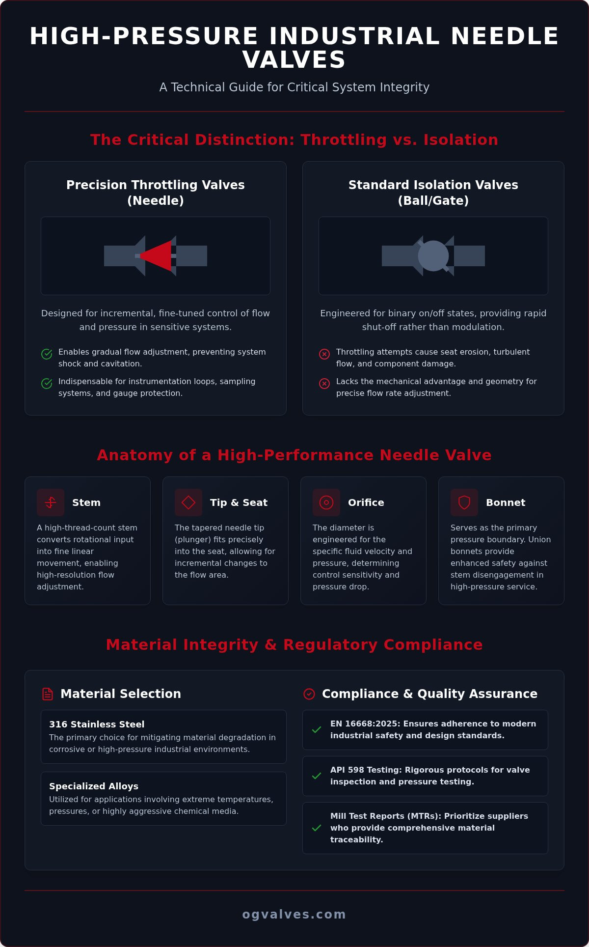
Industrial needle valves serve as the primary mechanical interface for high-precision throttling in pressurized fluid systems. Unlike isolation valves designed for binary open or closed states, these components feature a slender, tapered plunger that fits into a conical seat. This specific geometry allows for incremental control of flow rates, making them indispensable in environments where slight fluctuations in pressure can compromise system integrity. In heavy industrial sectors, the ability to modulate flow with extreme accuracy is a safety requirement rather than a performance preference. These valves are engineered to withstand rigorous operational demands while providing the resolution necessary for minute adjustments in flow velocity.
Throttling vs. Isolation: The Functional Distinction
The operational logic of industrial needle valves differs fundamentally from ball or gate valves. Ball valves utilize a 90-degree rotational path that provides rapid isolation but lacks the resolution required for fine adjustment. Attempting to throttle with a ball valve often leads to seat erosion and turbulent flow patterns. Conversely, the high-thread-count stem of a needle valve provides the mechanical advantage necessary for minute linear movement. This design ensures that the flow area changes gradually, reducing the risk of cavitation. Cavitation occurs when vapor bubbles form and collapse due to rapid pressure drops, which can cause severe pitting in lower-quality components. Proper specification prevents these hydraulic shocks by maintaining stable pressure gradients across the valve orifice, ensuring the longevity of the entire piping network.
Applications in Instrumentation and Sampling
Precision flow control is vital in instrumentation loops where sensitive equipment requires protection from sudden pressure spikes. Detailed Needle Valve Design and Operation documentation highlights their utility in protecting pressure gauges and transducers. By slowly opening the valve, operators prevent the “pegging” of gauges, which extends the calibration life of the instrument. In petrochemical refineries, these valves are critical in analytical sampling systems. They allow technicians to extract small, controlled volumes of process fluid for laboratory testing without disrupting the main flow line. In power generation, hydraulic control panels rely on these valves to regulate the movement of large actuators and turbines. The clinical precision of the needle-and-seat interface ensures that these systems respond predictably to manual or automated inputs, upholding the rigorous safety standards required for modern infrastructure.
Anatomy and Engineering Mechanics of Needle Valve Design
The mechanical efficacy of industrial needle valves depends on the precise coordination of the stem, tip, and orifice. A high-thread-count stem is critical for converting rotational input into minute linear displacement. This mechanical advantage allows for high-resolution flow adjustment, where multiple turns of the handle result in only a fraction of an inch of needle movement. The orifice diameter must be sized according to the process fluid’s velocity and pressure. A smaller orifice increases the potential pressure drop, which provides greater control sensitivity in low-flow applications. Engineers must choose between blunt and regulating tips based on the required flow profile. Regulating tips feature a consistent taper for linear flow characteristics, while blunt tips are better suited for repetitive shut-off cycles or coarse throttling. The valve bonnet serves as the primary pressure containment boundary. In high-pressure environments, union bonnets provide an extra layer of safety by preventing accidental stem disengagement during operation.
Stem and Seat Configurations
Space constraints in instrumentation manifolds often dictate the choice between rising and non-rising stems. Rising stems provide a clear visual indicator of the valve’s position, which is essential for manual process monitoring. Non-rising stems are preferred for compact installations where vertical clearance is limited. Metal-to-metal seating remains the standard for high-temperature reliability and structural durability. However, gas-phase applications frequently require soft-seat inserts to achieve a bubble-tight seal. Adherence to Regulatory Compliance Standards ensures that these configurations meet the specific safety thresholds required by the Department of Energy and other international oversight bodies. It’s vital to verify that seat materials are compatible with the chemical composition of the media to prevent premature erosion.
Sealing and Packing Mechanisms
Packing selection is determined by the thermal profile and chemical nature of the process fluid. PTFE packing is preferred for its superior chemical resistance and low friction at temperatures below 232°C. For extreme heat applications, graphite packing maintains seal integrity despite significant thermal expansion. The packing nut allows for precise field adjustments to compensate for seal wear over time. This capability is a critical factor in fugitive emission control and long-term leak prevention. Selecting components from an established technical supplier like OG Valves ensures that these mechanical tolerances are strictly maintained across high-pressure instrumentation inventories. This focus on engineering precision reduces the risk of packing failure in critical infrastructure loops.
Material Selection and Regulatory Compliance Standards
Material integrity is the primary determinant of safety in high-pressure fluid management. Grade 316/316L stainless steel remains the baseline specification for industrial needle valves due to its resistance to atmospheric corrosion and moderate chemical exposure. For environments involving high concentrations of chlorides or aggressive acids, engineers specify specialized alloys such as Monel, Hastelloy, or Inconel. These materials offer superior structural stability under extreme thermal and chemical loads. Super Duplex stainless steel provides an even higher threshold for pitting and crevice corrosion in marine applications. Positive Material Identification (PMI) testing serves as a mandatory verification protocol to ensure that the delivered component matches the metallurgical requirements of the project. This clinical approach to material verification prevents the installation of counterfeit or sub-standard alloys that could fail under operational stress.
Global Regulatory Benchmarks (ASME, API, ISO)
Global infrastructure projects demand adherence to rigorous regulatory frameworks to mitigate systemic risk. ASME B16.34 establishes the necessary pressure-temperature ratings and wall thickness requirements for valve bodies. For the European market, compliance with the Pressure Equipment Directive (2014/68/EU) and the updated EN 16668:2025 standard is mandatory for metallic valves where allowable pressure exceeds 0.5 bar. Testing protocols defined by API 598 require shell and seat pressure tests at 1.5 times the maximum working pressure to confirm zero-leakage performance. Procurement specialists must also account for the definitive phase of the EU Carbon Border Adjustment Mechanism (CBAM) that began on January 1, 2026, which impacts the cost of raw materials. Additionally, new U.S. Section 301 tariffs effective July 24, 2026, impose rates of 10% to 12.5% on products from various economies, making material traceability even more critical for cost management. It’s essential to verify that all components carry the necessary certifications to avoid regulatory non-compliance.
Corrosion Resistance in Petrochemical Environments
Corrosion management in petrochemical systems requires a deep understanding of Pitting Resistance Equivalent Number (PREN) values. A higher PREN indicates greater resistance to localized pitting in chloride-rich environments, which is a common failure point for industrial needle valves in coastal refineries. Stress Corrosion Cracking (SCC) remains a significant risk in systems exposed to high temperatures and tensile stress. To mitigate these risks, material selection must align with NACE MR0175/ISO 15156 standards for sour gas applications. This standard limits the hardness of materials to prevent sulfide stress cracking in the presence of hydrogen sulfide (H2S). Proper alloy selection, combined with rigorous material traceability back to the mill, ensures that the valve maintains its mechanical properties throughout its intended service life. Technical experts prioritize these data-driven selection criteria to ensure long-term operational safety in aggressive chemical media.
Technical Factors for Sizing and Specification
Engineering a high-pressure instrumentation loop requires more than matching pipe diameters. Specifying industrial needle valves based solely on connection size often leads to system inefficiency or component failure. Accurate sizing involves a clinical analysis of the flow coefficient, pressure-temperature (P-T) ratings, and fluid dynamics. Precise specification ensures that the valve operates within its intended range, typically between 10% and 90% of its stem travel. Operating outside these parameters increases the risk of seat erosion and reduces control resolution. Engineers must account for the specific gravity and viscosity of the media, as these factors directly influence the pressure drop across the valve orifice. A comprehensive technical approach eliminates the guesswork associated with surface-level procurement.
Calculating Flow Coefficient (Cv) for Needle Valves
The Flow Coefficient (Cv) serves as the primary metric for determining the capacity of a throttling component. Cv is the volume of water in US gallons per minute that will flow through a valve with a 1 psi pressure drop. Liquid flow calculations use a straightforward relationship between flow rate, pressure drop, and specific gravity. Gas flow requires more complex formulas to account for compressibility, inlet pressure, and absolute temperature. The Cv of a needle valve is not a static value; it changes relative to the number of stem turns. This characterized flow allows for the minute adjustments necessary in chemical injection and sampling systems. You can access technical support and high-precision components by browsing the industrial needle valves available through OG Valves. Understanding the Cv profile ensures the valve isn’t oversized, which would result in “hunting” or poor control sensitivity.
Managing Pressure Drops and Velocity
High differential pressures across a small orifice create significant mechanical stress. If the pressure drop exceeds the vapor pressure of a liquid, flashing or cavitation occurs. These phenomena result in rapid material degradation and audible noise. Fluid velocity must remain within safe mechanical limits to prevent abrasive wear on the needle tip and seat. For gas applications, velocities should typically remain below Mach 0.3 to avoid choked flow conditions. The relationship between orifice size and flow turbulence is critical. A smaller orifice increases velocity but also increases the potential for turbulence-induced vibration. P-T ratings, defined by standards such as ASME B16.34, establish the maximum allowable pressure at specific temperatures. These limits must never be exceeded, even during transient system surges.
End connections must align with the existing piping architecture and safety requirements. Common options include:
- NPT (National Pipe Thread): The standard for most North American instrumentation, relying on thread deformation for a seal.
- BSPP (British Standard Parallel Pipe): Utilizes a bonded seal or O-ring, preferred for high-pressure hydraulic systems in international markets.
- Compression Fittings: Provide a mechanical, flareless grip on tubing, ideal for high-vibration environments where leak-tight integrity is paramount.
Strategic Procurement and Quality Assurance in Valve Supply
Procurement of high-pressure components like industrial needle valves is a critical risk-management exercise for technical specialists. It’s not enough to source a part that meets basic dimensional criteria; the supplier must demonstrate a deep understanding of the metallurgical and regulatory demands of heavy industry. Documentation remains the primary form of brand validation in these sectors. Mill Test Reports (MTRs) provide the necessary heat numbers and chemical compositions required for material traceability back to the mill. Certificates of Conformity verify that the component adheres to the specific international standards discussed previously, such as API 598 or ASME B16.34. Without these documents, the risk of quality fade or regulatory non-compliance in corrosive environments becomes an unacceptable operational liability.
Vetting Industrial Valve Suppliers
Evaluating a supplier’s inventory depth is essential for maintaining project timelines. A dependable partner must stock diverse material grades, from standard 316 stainless steel to specialized Super Duplex alloys. This technical expertise ensures that the procurement process aligns with the long-term safety requirements of the infrastructure. A supplier’s understanding of global industrial standards prevents the acquisition of components that fail to meet the EN 16668:2025 benchmarks. For a broader perspective on component selection across various pressure classes, engineers should consult our comprehensive guide to industrial valves. This resource outlines the fundamental standards that govern high-specification fluid systems and helps procurement specialists avoid common specification errors.
OG Valves: Engineering-Led Supply Solutions
OG Valves utilizes a clinical approach to technical specification and quality assurance. Our logistics framework is designed for global energy projects where fast-track delivery is a necessity rather than an option. Minimizing downtime in critical infrastructure requires a supplier with established global supply chains and a Northern Ireland-based technical support team. While industrial needle valves provide the precision required for throttling, it’s also necessary to understand how they integrate with other system components. You can compare these with gate valve mechanisms to determine the best fit for isolation versus flow modulation. This engineering-led perspective ensures that every component contributes to the overall structural soundness and operational output of the system. Reliable procurement results in long-term performance and the mitigation of catastrophic system failures.
Securing Precision and Integrity in Future Infrastructure
The operational safety of high-pressure systems depends on the clinical integration of mechanical precision and material science. Selecting industrial needle valves requires a deep understanding of flow coefficients, pressure-temperature ratings, and the specific corrosion profiles of the process media. Adhering to international benchmarks such as ASME B16.34 and API 598 remains the only viable method for mitigating systemic risk in heavy industry. These technical standards provide a framework for long-term durability and regulatory compliance. Precision in component specification is the primary defense against catastrophic system failure.
Maintaining infrastructure reliability demands a supply partner with global logistics capabilities and technical expertise. OG Valves offers strict adherence to API and ASME standards alongside comprehensive project management for complex engineering requirements. Our global supply chain expertise ensures that high-specification components reach your site without compromising project timelines. Contact OG Valves for technical specifications or a procurement quote to align your procurement strategy with the highest benchmarks of engineering excellence. Your commitment to quality assurance ensures the continued safety and efficiency of your critical operations.
Frequently Asked Questions
What is the primary difference between a needle valve and a globe valve?
Needle valves feature a much finer, tapered stem tip compared to the disk-shaped plug found in globe valves. This geometric distinction allows for high-resolution flow adjustment in low-flow instrumentation loops. While globe valves manage larger volumes and provide moderate throttling, needle valves are specialized for minute calibration. Their high-thread-count stems enable precise linear movement. It’s the standard for applications requiring exact flow modulation rather than general volume control.
Can industrial needle valves be used for bubble-tight isolation?
Industrial needle valves achieve bubble-tight isolation primarily when specified with soft-seat inserts made of materials like PTFE or PEEK. Metal-to-metal seats are engineered for high-temperature and high-pressure reliability but may require higher torque to achieve a zero-leakage seal in gas applications. Most high-specification valves are tested under API 598 protocols to ensure seat integrity. For gas-phase media where absolute shut-off is mandatory, soft-seated configurations provide the necessary seal resilience to prevent fugitive emissions.
How do I determine the correct material for a needle valve in a sour gas environment?
Material selection for sour gas environments must strictly adhere to NACE MR0175/ISO 15156 standards to prevent sulfide stress cracking. You should specify materials with controlled hardness levels, such as 316 stainless steel or specialized nickel alloys like Inconel 625. Positive Material Identification (PMI) testing is required to verify the metallurgical composition before installation. Selecting the correct alloy prevents hydrogen-induced cracking in systems containing hydrogen sulfide. Technical support from global suppliers helps ensure that all components meet these safety thresholds.
What are the pressure limits for standard stainless steel needle valves?
Standard 316 stainless steel industrial needle valves typically operate within pressure ranges of 3,000 to 10,000 PSI at ambient temperatures. Specialized high-pressure designs can accommodate hydraulic loads up to 60,000 PSI in ultra-high-pressure instrumentation systems. It’s critical to consult the Pressure-Temperature (P-T) charts defined by ASME B16.34 to determine the safe working limit at operational temperatures. Exceeding these limits compromises the structural integrity of the valve body and the safety of the surrounding infrastructure.
Why is Flow Coefficient (Cv) more important than pipe size for needle valves?
The Flow Coefficient (Cv) is a more critical engineering metric than connection size because it quantifies the actual flow capacity of the valve. Pipe size only defines the physical connection to the system, whereas Cv accounts for the internal orifice geometry and the pressure drop across the component. Sizing a valve based solely on NPT or BSPP threads often leads to oversized components that lack control sensitivity. Accurate Cv calculations ensure the valve operates within its optimal throttling range for precise modulation.
Are needle valves suitable for high-viscosity fluids or slurries?
Needle valves aren’t typically suitable for high-viscosity fluids or media containing suspended solids. The narrow flow path and small orifice are highly susceptible to clogging and abrasive wear when exposed to slurries. These conditions can cause the tapered needle to seize or prevent the valve from achieving a complete shut-off. In such applications, plug valves or ball valves are preferred as they provide a clearer flow path. Precision throttling is best reserved for clean gases and low-viscosity liquids.
What maintenance is required for needle valves in high-cycle applications?
High-cycle applications require regular inspection of the stem packing and seat surfaces to maintain seal integrity. You should adjust the packing nut periodically to compensate for PTFE or graphite wear and prevent fugitive emissions. In high-pressure environments, the needle tip should be examined for signs of erosion or wire-drawing, which can compromise throttling accuracy. Maintaining a consistent lubrication schedule for the stem threads reduces friction and prevents galling. These proactive measures extend the operational lifespan of critical instrumentation components.
How does temperature affect the pressure rating of an industrial needle valve?
Increasing temperatures significantly reduce the maximum allowable pressure rating of an industrial needle valve. As thermal energy increases, the mechanical strength of the valve body material decreases, requiring a de-rating of the system’s working pressure. This relationship is plotted on P-T curves specified by ASME and EN standards. For example, a valve rated for 10,000 PSI at 38°C may only be rated for 6,000 PSI at 200°C. Engineers must verify these limits to prevent catastrophic structural failure.
 Responsive Menu