A single dimensional mismatch in a high-pressure piping system is not merely a procurement error; it is a catastrophic point of failure that compromises the structural integrity of the entire infrastructure. Technical experts and procurement specialists frequently encounter critical interoperability failures when attempting to bridge the gap between ASME and EN components. You recognize that mastering industrial valve flange standards requires a clinical understanding of material de-rating and the complex overlap of API and ASME protocols. Precision in these specifications is the only safeguard against operational downtime and safety breaches.
This technical guide provides a comprehensive analysis of global flange standards, incorporating the February 2026 updates to ISO 5211 and the revised ANSI/MSS SP-44-2026 requirements. We will establish a clear framework for selecting the correct flange configurations based on pressure-temperature limitations and regulatory adherence. The following sections detail the essential data points required to verify compliance with international safety protocols and ensure seamless integration across global supply chains.
Key Takeaways
- Understand the mechanical role of flanges as rigid, restrained joints and how their specific geometry facilitates critical system maintenance and component replacement.
- Analyze the hierarchy between mandatory codes and guideline-based industrial valve flange standards to ensure interoperability across ASME, API, and EN 1092-1 frameworks.
- Master the application of pressure-temperature ratings defined in ASME B16.34 to prevent material failure in high-stress industrial environments.
- Evaluate the mechanical advantages of various flange facing types, such as Raised Face (RF) configurations, to achieve optimal gasket compression and leak-proof seals.
- Implement rigorous quality assurance protocols, including Positive Material Identification (PMI), to verify metallurgical integrity and compliance during technical procurement.
Fundamentals of Industrial Valve Flange Geometry and Design
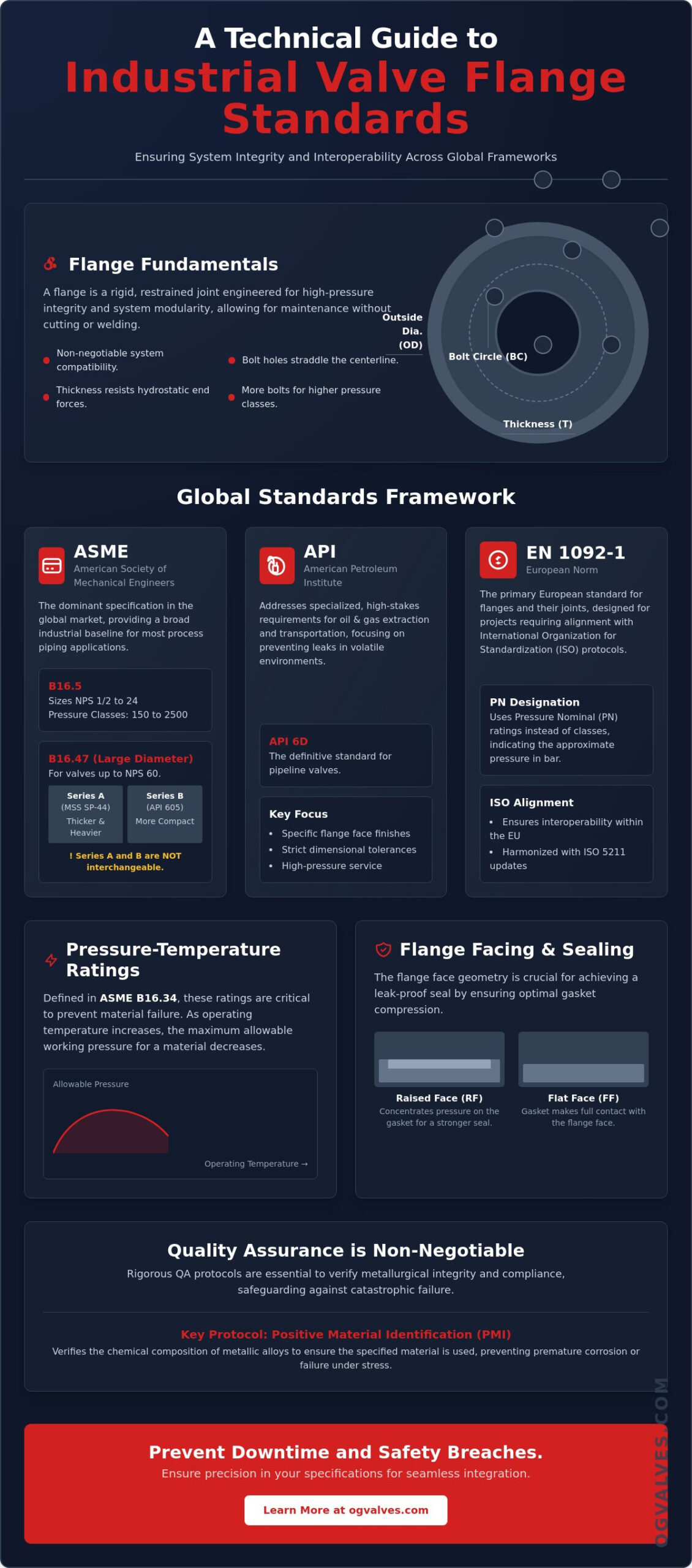
An industrial flange serves as a rigid, restrained joint engineered for high-pressure integrity. It’s a foundational element in heavy industrial piping systems. Beyond simple connection, flanges facilitate system maintenance and component replacement. Engineers can isolate and remove valves without cutting or welding pipe sections. This modularity depends entirely on the rigorous application of industrial valve flange standards to ensure that all mating parts align without mechanical interference.
Three primary dimensional variables define a flange: Outside Diameter (OD), Bolt Circle (BC), and thickness. The Outside Diameter and Bolt Circle are non-negotiable parameters for system compatibility. The OD defines the total footprint of the connection, while the BC dictates the exact placement of the fasteners. Standard bolt pattern orientation is also a requirement; bolt holes must straddle the vertical centerline rather than sitting directly on it. This uniformity allows for predictable alignment during field installation, even when components originate from different global supply chains.
Essential Dimensional Parameters for Specification
Bolt hole quantity is a direct function of pressure containment capabilities. As the pressure class increases, the number of bolts increases to distribute the clamping force evenly across the joint. Flange thickness (T) isn’t arbitrary; it’s calculated to resist hydrostatic end forces that attempt to pull the joint apart during operation. Additionally, the gasket seating surface plays a clinical role in preventing fugitive emissions. The surface finish must match the gasket material to achieve a gas-tight seal under high-stress conditions, maintaining the structural soundness of the valve assembly.
The Structural Role of the Flange Connection
The flange acts as a load-transferring element that anchors the valve to the piping system. It provides essential resistance to longitudinal stress and significant bending moments that occur during thermal expansion or pressure surges. In industrial applications, the distinction between restrained flange joints and non-restrained mechanical connections is critical. A flanged joint maintains a fixed position under load, ensuring the safety of the entire pressure vessel. Non-restrained joints may allow for axial movement, which is unacceptable in high-pressure valve applications. Adherence to Flange standards worldwide ensures that these structural loads are calculated and managed according to established engineering benchmarks.
Global Standards Framework: ASME, API, and EN 1092-1
The global regulatory landscape for industrial valve flange standards relies on a structured hierarchy where legal codes mandate the use of specific engineering guidelines. ASME B16.5 remains the dominant specification in the global market, defining the dimensions and tolerances for most process piping applications. While ASME provides a broad industrial baseline, API standards address the specialized requirements of high-stakes oil and gas extraction and transportation. Projects requiring alignment with International Organization for Standardization (ISO) protocols typically look to the European Norm EN 1092-1. For detailed information on how these apply to specific valve types, consult our Technical Guide to Industrial Gate Valves.
ASME B16.5 vs. ASME B16.47: Size and Scope
ASME B16.5 defines the parameters for pipe flanges and flanged fittings from NPS 1/2 through NPS 24, covering pressure classes from 150 to 2500. When system requirements exceed these dimensions, ASME B16.47 governs large-diameter valves up to NPS 60. This standard is divided into Series A (formerly MSS SP-44) and Series B (formerly API 605). Series A flanges are typically thicker and heavier, while Series B offers a more compact bolt circle for space-sensitive applications. These dimensional nuances are critical in industrial flange design, as the two series are not interchangeable and require different bolting and gasket specifications.
API Standards for Critical High-Pressure Service
API 6D is the definitive standard for pipeline valves, mandating specific flange face finishes and dimensional tolerances to prevent leaks in volatile environments. In upstream applications, API 6A governs wellhead and Christmas tree equipment. These standards often utilize high-strength alloys and specialized ring-type joints (RTJ) to manage pressures that exceed standard ASME classes. Compliance with API is a prerequisite for most offshore and petrochemical installations where the cost of failure is absolute. Procurement specialists should verify these certifications when sourcing high-performance ball valves for critical infrastructure.
EN 1092-1 and ISO Alignment
EN 1092-1 is the primary European standard, utilizing the PN (Pressure Nominal) rating system. Unlike the ASME class system, PN ratings correspond to the maximum allowable pressure in bar at room temperature. Common ratings include PN10, PN16, and PN40. Mating PN-rated flanges with ASME-classed components presents significant interoperability challenges. Bolt hole diameters and circle dimensions rarely align exactly. ISO 7005-1 provides a technical bridge for international harmonization, though specialists must verify exact drill patterns before finalizing a specification. The February 2026 updates to several ISO and CEN standards emphasize this need for improved interoperability across global fluid handling systems.
Analysis of Pressure Classes and Temperature Ratings
Mechanical integrity in high-pressure systems depends on the precise alignment of operational parameters with established industrial valve flange standards. ASME B16.5 and B16.34 define the primary pressure classes: #150, #300, #600, #900, #1500, and #2500. These designations don’t represent a static pressure limit in pounds per square inch across all thermal ranges. Instead, they serve as a reference for the “Pressure-Temperature Ratings” defined in ASME B16.34. This standard dictates how the maximum allowable pressure of a valve decreases as the operating temperature rises.
Material selection significantly alters the pressure ceiling for any given class. Carbon steel (ASTM A105) provides high strength at ambient temperatures but loses structural rigidity faster than austenitic stainless steels (ASTM A182 F316) as thermal energy increases. Conversely, stainless steel often has a lower pressure rating at ambient temperatures compared to carbon steel within the same class. Engineers must also account for thermal expansion and the risks of cold working. Sudden temperature shifts can cause localized stress concentrations, potentially exceeding the material’s yield strength and leading to flange deformation or gasket failure.
The Relationship Between Class and Operational Pressure
The maximum allowable working pressure (MAWP) for a Class 150 carbon steel flange at ambient temperature is approximately 285 psi. As the class increases to #2500, the MAWP scales to 6170 psi under similar conditions. To ensure safety, hydrostatic test pressure requirements are typically set at 1.5 times the MAWP at 100°F (38°C). Increased flange thickness is the primary mechanical response to these requirements. Thicker flange rings provide the necessary cross-sectional area to resist internal pressure surges and the longitudinal forces acting on the valve body.
Temperature De-rating and Material Limits
Temperature de-rating is the reduction of allowable pressure as thermal energy increases. This clinical adjustment is necessary because material tensile strength degrades at elevated temperatures. For extreme environments, specialized materials like Super Duplex or Inconel are specified for their superior creep resistance. These alloys maintain their mechanical properties under sustained high-temperature stress where standard steels would undergo permanent deformation. Consult our Industrial Valve Specification Guide for detailed material selection protocols tailored to specific environmental applications.
Flange Facing Types and Gasket Compatibility
Flange faces serve as the physical interface where the sealing mechanism is established. Adherence to industrial valve flange standards ensures these surfaces provide the necessary friction and compression to maintain a leak-proof joint under operational stress. The specific geometry of the flange face determines how the bolt load is distributed across the gasket material, directly impacting the system’s ability to contain volatile or high-pressure media. It’s a critical specification point that defines the reliability of the entire piping assembly.
Raised Face (RF) vs. Flat Face (FF) Considerations
The Raised Face (RF) is the industry standard for steel valve applications. This design features a circular area raised above the bolting ring, typically 1.6mm for Class 150 and 300, or 6.4mm for Class 400 and higher. This elevation concentrates the clamping force onto a localized gasket area, effectively increasing the sealing pressure without requiring excessive torque. For optimal adhesion, these surfaces require a serrated finish, usually a phonographic or concentric groove pattern. This texture prevents gasket extrusion and maintains the seal during thermal cycling.
Flat Face (FF) flanges are utilized primarily with brittle materials such as cast iron or bronze. Because these materials lack the ductility of steel, they can’t withstand the bending moments generated by a raised face. Mating a Raised Face steel flange to a Flat Face cast iron valve body is a significant safety risk. When the bolts are tightened, the cantilever effect created by the 1.6mm gap can crack the cast iron flange, leading to immediate structural failure. When procuring components for diverse systems, you should consult the Industrial Valve Specification Guide to ensure matching facing types and uniform load distribution.
Ring Type Joint (RTJ) for Critical Sealing
Ring Type Joint (RTJ) facings are engineered for ultra-high-pressure and high-temperature service, typically appearing in Class 600 and above. This configuration uses a metal-to-metal seal mechanism where an octagonal or oval ring is compressed into a precision-machined groove. RTJ seals are exceptionally reliable because they’re less susceptible to the chemical degradation or thermal softening that affects non-metallic gaskets. Precise material selection is vital; the ring gasket must always be softer than the flange material to ensure it deforms into the groove without damaging the machined surfaces of the valve. This plastic deformation creates a gas-tight seal capable of withstanding the most demanding industrial environments.
Quality Assurance and Specification in Valve Procurement
Precise technical data sheets are the primary defense against procurement errors in heavy industrial sectors. When specifying components, a clinical focus on documentation ensures that every physical dimension aligns with the required industrial valve flange standards. Vague specifications often lead to the acquisition of “equivalent” parts that lack the necessary metallurgical properties for high-pressure service. Technical experts must demand granular data, including exact material classifications and pressure-temperature de-rating values, to maintain the structural survival of the system.
Positive Material Identification (PMI) is a mandatory quality assurance protocol for verifying flange metallurgy. This non-destructive testing method confirms that the chemical composition of the alloy matches the Material Test Report (MTR) exactly. In environments involving corrosive media or extreme thermal cycling, even a minor deviation in chromium or nickel content can lead to premature stress corrosion cracking. OG VALVES anchors its quality control processes in these rigorous testing benchmarks, ensuring that every component meets the latest 2026 ISO and API certifications before deployment into critical infrastructure.
Avoiding Interoperability and Regulatory Failures
High-pressure containment systems don’t have the tolerance for non-standardized components. The use of flanges that lack documented traceability introduces unacceptable risks of catastrophic failure. MTRs are essential documents that provide a comprehensive history of the material’s mechanical and chemical properties, including yield strength and heat treatment records. Adherence to certifications from global bodies like the API and ISO is the only reliable method for establishing high-stakes trust. These standards ensure that components from different manufacturers will function as a unified, leak-proof assembly. For specific application data regarding part-turn isolation, refer to our Butterfly Valve Specification Guide.
OG VALVES: Technical Expertise and Global Supply
We act as a specialist partner for high-specification industrial projects, providing the technical support necessary to navigate complex international standards. Our engineering team assists procurement specialists in defining precise specifications for gate, ball, and globe valves, ensuring that all flanged connections meet the specific environmental demands of the project. We understand that the cost of failure in heavy industry is absolute. Consequently, our global logistics network is optimized for fast-track delivery, allowing for the rapid replacement of critical components without compromising quality assurance protocols. This commitment to engineering excellence and operational output positions us as a dependable entity in the global fluid handling market.
Securing System Integrity Through Standardized Specification
Adhering to rigorous industrial valve flange standards is a fundamental requirement for the structural survival of high-pressure industrial systems. You’ve seen how precise geometry, clinical material de-rating, and facing compatibility dictate the reliability of critical infrastructure. As global standards like ISO 5211 and ANSI/MSS SP-44-2026 continue to evolve, maintaining compliance requires a partner with deep technical expertise and a robust supply chain. Precision at the procurement stage eliminates the risk of interoperability failure and ensures long-term operational safety.
OG VALVES maintains an extensive inventory of high-specification industrial valves, including gate, ball, and butterfly configurations, all tested to meet the most demanding benchmarks. Our technical expertise in API and ASME standards ensures your specifications are accurate and verified. We utilize a global logistics network to provide fast-track delivery, ensuring your project timelines remain intact without compromising safety or quality. Every component is backed by rigorous testing and comprehensive documentation to guarantee regulatory adherence.
Consult with our technical experts for your industrial valve specifications to ensure your next installation meets every regulatory and mechanical benchmark. We’re ready to support your high-stakes infrastructure needs.
Frequently Asked Questions
What is the difference between ASME B16.5 and ASME B16.47?
The primary distinction lies in the nominal pipe size (NPS) coverage. ASME B16.5 governs flanges from NPS 1/2 through NPS 24, while ASME B16.47 is the technical specification for large-diameter flanges from NPS 26 through NPS 60. Additionally, B16.47 is divided into Series A and Series B, which feature different bolt circle diameters and flange thicknesses that aren’t interchangeable.
Can I connect an ASME #150 flange to an EN 1092-1 PN16 flange?
Direct connection is generally impossible due to dimensional misalignment in bolt hole patterns and bolt circle diameters. While both ratings are common in process piping, they originate from different regulatory frameworks. Attempting to force a connection between these standard systems compromises the structural integrity of the joint and increases the risk of catastrophic leakage.
What does the “Class” rating on an industrial valve flange signify?
The “Class” rating identifies the pressure-temperature ceiling for a specific material group. It’s a core component of industrial valve flange standards that dictates the maximum allowable working pressure (MAWP) at various thermal levels. For example, a Class 300 flange has a significantly higher pressure ceiling at ambient temperature than it does at its maximum rated thermal limit.
Why is a Raised Face (RF) flange the most common choice in heavy industry?
A Raised Face (RF) flange concentrates the entire bolt load onto a smaller, localized gasket surface area. This mechanical advantage increases the sealing pressure, ensuring a gas-tight joint in standard industrial applications. It’s the preferred choice for steel valves because it effectively prevents gasket extrusion and maintains seal integrity during thermal cycling.
When should a Ring Type Joint (RTJ) flange be specified over a Raised Face?
Specify a Ring Type Joint (RTJ) for high-pressure service, typically Class 600 and higher, or for applications involving extreme temperatures and volatile media. RTJ utilizes a metal-to-metal seal mechanism that remains stable under conditions where resilient gaskets might undergo thermal softening or chemical degradation. RF remains the standard for lower-pressure process piping where standard gaskets are sufficient.
How does temperature affect the pressure rating of a stainless steel flange?
Stainless steel undergoes significant pressure de-rating as operating temperatures increase due to the reduction in material tensile strength. For instance, an ASTM A182 F316 Class 150 flange de-rates from 275 psi at 100°F to approximately 140 psi at 600°F. Engineers must consult the specific de-rating tables in ASME B16.34 to ensure the valve maintains its mechanical endurance throughout the operational range.
What are the risks of mixing Flat Face and Raised Face flanges?
Mating a Raised Face (RF) flange to a Flat Face (FF) flange creates a high risk of structural failure, particularly when using brittle materials like cast iron. The raised portion acts as a fulcrum, generating a bending moment that can crack the flange ring when bolts are torqued to specification. Always use matching face types to ensure uniform load distribution across the joint.
Which flange standards are required for offshore oil and gas applications?
Offshore oil and gas installations primarily require adherence to API 6A and API 6D industrial valve flange standards. These certifications mandate higher safety factors, specific metallurgical requirements, and rigorous testing protocols to withstand corrosive subsea environments and extreme pressures. Ring Type Joint (RTJ) facings are frequently specified in these high-stakes applications to guarantee a gas-tight seal.
 Responsive Menu