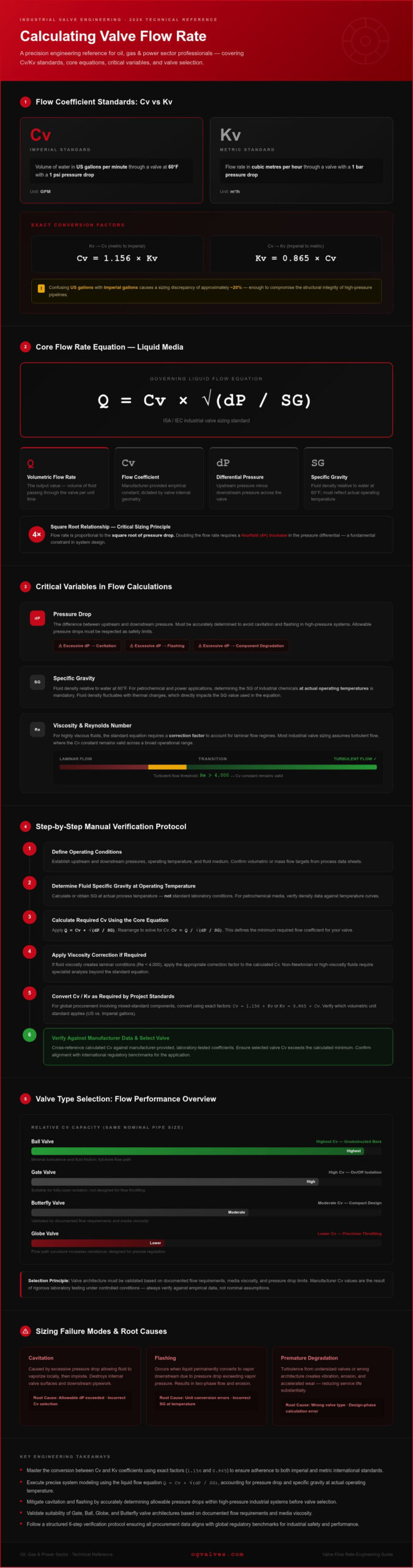
A single mathematical error during the initial design phase can compromise the structural integrity of an entire critical infrastructure project. For technical experts in the oil, gas, and power sectors, calculating valve flow rate is not merely a preliminary task; it’s a fundamental safety protocol. Inaccurate sizing often results in severe operational failures, including cavitation, flashing, and premature component degradation. You likely recognize that the transition between Cv and Kv standards, or the complexities of non-standard viscosities, introduces unacceptable levels of risk into your procurement process.
This 2026 guide serves as a clinical resource to eliminate ambiguity and ensure your valve selections meet rigorous global benchmarks. You’ll master the engineering principles and specific formulas required to verify flow rates across various media and pressure gradients. We provide a methodical, step-by-step verification process that addresses high-pressure environments and ensures compliance with international engineering standards. By the conclusion of this technical briefing, you’ll possess a reliable framework for selecting Gate, Ball, or Globe valves that align with documented operational outputs and safety requirements. This documentation prioritizes industrial precision to maintain the durability and regulatory adherence your infrastructure demands.
Key Takeaways
- Establish technical precision by mastering the conversion between Cv and Kv coefficients; this ensures adherence to both imperial and metric international standards.
- Execute precise system modeling by calculating valve flow rate using liquid flow equations that account for pressure drop and specific gravity.
- Mitigate the risk of cavitation and flashing by accurately determining allowable pressure drops within high-pressure industrial systems.
- Validate the suitability of specific architectures, including Gate and Butterfly valves, based on documented flow requirements and media viscosity.
- Follow a structured verification protocol to ensure all procurement data aligns with global regulatory benchmarks for industrial safety and performance.
Understanding the Flow Coefficient: Cv and Kv Standards
The flow coefficient is the fundamental metric used to quantify a valve’s hydraulic capacity. It is a constant value dictated by the internal geometry of the valve, including the orifice size, flow path curvature, and surface finish. For engineering teams, the coefficient provides a standardized way to predict pressure drop across a valve under specific flow conditions. Cv is the imperial standard, defined as the volume of water in US gallons per minute that flows through a valve at 60°F with a 1 psi pressure drop. Its metric counterpart, Kv, represents the flow rate in cubic metres per hour with a 1 bar pressure drop. Understanding the distinction between these two units is the first step in accurately calculating valve flow rate for large-scale industrial systems.
The Importance of Cv in Valve Sizing
Cv allows engineers to conduct direct performance comparisons between different valve designs. For instance, a Ball valve generally possesses a significantly higher Cv than a Globe valve of the same nominal pipe size. This is because the Ball valve’s unobstructed bore minimizes turbulence and fluid friction. When calculating valve flow rate for high-pressure systems, the Cv rating indicates the upper limits of fluid transport. Relying on manufacturer-provided data is essential, as these values are the result of rigorous laboratory testing conducted under controlled conditions. This empirical data ensures that the flow coefficient (Cv and Kv) used in your calculations reflects the actual mechanical capabilities of the hardware, preventing downstream issues like restricted flow or insufficient pressure delivery.
Converting Between Cv and Kv
Global infrastructure projects frequently require the integration of components manufactured to different regional standards. To maintain technical consistency, you must use the exact conversion factor: Cv = 1.156 x Kv. If you’re working from metric specifications to determine imperial requirements, the formula is Kv = 0.865 x Cv. Precise conversion is critical in global procurement to avoid sizing errors that could lead to system cavitation or flashing. One frequent error involves the confusion between US gallons and Imperial gallons; using the wrong volumetric unit will result in a sizing discrepancy of approximately 20%. Such errors can compromise the structural integrity of high-pressure pipelines. By applying these factors correctly, you ensure that the specified Gate, Ball, or Needle valves align perfectly with the hydraulic demands of the project, regardless of the origin of the technical drawings. This clinical approach to unit conversion is a prerequisite for maintaining regulatory adherence across international supply chains.
Fundamental Equations for Calculating Valve Flow Rate
Precise manual verification of hydraulic data is the only way to ensure component longevity in high-pressure systems. Relying solely on automated software without understanding the derivation of the results introduces a margin for error that industrial standards don’t permit. When calculating valve flow rate for liquid media, the governing equation is Q = Cv * sqrt(dP / SG). In this formula, Q represents the volumetric flow rate, dP is the differential pressure, and SG is the specific gravity of the fluid relative to water at 60°F. Pressure drop is defined as the difference between the upstream and downstream pressure. This relationship demonstrates that flow rate is proportional to the square root of the pressure drop; doubling the flow requires a fourfold increase in the pressure differential.
Liquid Flow Calculations
In petrochemical and power applications, determining the specific gravity of industrial chemicals at actual operating temperatures is mandatory. Fluid density fluctuates with thermal changes, which directly impacts the SG value used in the equation. For highly viscous fluids, the standard equation requires a correction factor to account for laminar flow regimes. Most industrial valve sizing assumes turbulent flow, where the Reynolds number exceeds 4,000, ensuring the Cv constant remains valid across a broad operational range. If your application involves non-Newtonian fluids or high-viscosity chemicals, consulting with the technical team at OG VALVES can provide clarity on housing material durability and flow efficiency for specific Gate or Globe valve configurations.
Gas and Steam Flow Considerations
Compressible fluids like steam and natural gas necessitate a more complex analytical approach. Unlike liquids, the density of a gas changes as it passes through the valve’s internal geometry. Engineers must introduce an expansion factor to account for this change in specific weight and the resulting pressure recovery. A critical threshold in calculating valve flow rate for gases is the phenomenon of choked flow. This occurs when the fluid reaches sonic velocity at the valve’s vena contracta, at which point further decreases in downstream pressure won’t increase the flow rate. Accurate gas flow modeling also requires absolute temperature and pressure corrections to maintain compliance with API and ANSI standards. Ignoring these variables leads to undersized valves that can’t meet peak demand or oversized valves prone to control instability and seat erosion.
Critical Variables: Pressure Drop, Specific Gravity, and Viscosity
Analytical precision in calculating valve flow rate requires more than a basic understanding of volumetric throughput. Environmental variables and media-specific characteristics dictate the operational reliability of a system. Inaccurate assessment of pressure drop or fluid density often leads to premature component failure and unexpected downtime. Specific Gravity (SG) represents the ratio of the density of a substance to the density of water at a specific temperature. It directly influences the force required to move a fluid through a valve’s internal geometry. In petrochemical applications, SG is rarely static. Temperature fluctuations alter fluid density significantly; for instance, heating crude oil reduces both its viscosity and SG, which increases the flow rate for a given pressure drop. Engineers must verify SG values based on the actual operating temperature rather than standard ambient conditions to ensure calculation accuracy.
Managing Pressure Drop (dP)
Pressure drop represents the energy lost as fluid overcomes the internal resistance of the valve housing and trim. Excessive dP increases the energy consumption of pumps and compressors, resulting in higher operational costs. More critically, high pressure differentials can cause the fluid velocity to increase to the point where local pressure falls below the vapor pressure of the liquid. This triggers flashing and cavitation, which are particularly destructive to check valves where rapid pressure changes cause seat pitting and structural fatigue. Industry best practices suggest that a dP should not exceed 10% of the upstream pressure for liquid systems to maintain stability and protect internal components from erosion.
Viscosity and the Reynolds Number
Standard Cv formulas assume a fully turbulent flow regime. This assumption fails when dealing with heavy polymers, resins, or cold crude oil. High-viscosity fluids create significant internal friction, necessitating a viscosity correction factor (Fr). To determine if a correction is required, you must calculate the Reynolds Number (Re), which relates inertial forces to viscous forces within the fluid stream. The flow regime is categorized as follows:
- Laminar Flow (Re < 2,000): Viscous forces dominate. Standard Cv formulas will significantly underestimate the required valve size in this state.
- Transitional Flow (Re 2,000 to 4,000): Flow stability is unpredictable. Precision sizing requires empirical correction to account for fluctuating resistance.
- Turbulent Flow (Re > 4,000): Inertial forces dominate, and standard Cv calculations remain accurate for most industrial applications.
Applying the viscosity correction factor to the base Cv ensures the selected valve can handle increased resistance without causing a system bottleneck. This technical rigor is essential for maintaining the operational output of critical infrastructure. When calculating valve flow rate for non-standard fluids, these variables must be prioritized to maintain the durability of stainless steel and carbon steel housings in high-flow environments.
Step-by-Step Procedure for Manual Flow Rate Verification
Manual verification remains the definitive method for ensuring mechanical integrity in the field, especially when proprietary software is unavailable. When calculating valve flow rate, engineers must follow a methodical five-step protocol to validate procurement specifications and prevent system bottlenecks. This structured approach ensures that the physical hardware can withstand the hydraulic stresses of the application while maintaining the required volumetric output.
- Step 1: Identify Media Properties. Record the fluid type, specific gravity at actual operating temperature, and dynamic viscosity. Do not rely on ambient temperature data for high-heat petrochemical processes.
- Step 2: Define System Requirements. Establish the target volumetric flow rate or the maximum allowable pressure drop based on the pump’s curve and system resistance.
- Step 3: Select Preliminary Valve Type. Choose a baseline architecture, such as a high-performance Ball Valve or a Globe valve, to identify the standard Cv ratings available for that geometry.
- Step 4: Execute the Calculation. Apply the standard liquid or gas equations discussed previously to derive the required flow coefficient (Cv).
- Step 5: Compare Against Specifications. Match the calculated Cv against the manufacturer’s published data. Ensure the required Cv falls within the 60% to 80% open range for control applications to maintain optimal modulation.
Initial Data Collection
Consistency in unit measurement is mandatory. Discrepancies between US GPM and metric cubic metres per hour will result in catastrophic sizing failures. You must verify the calibration of upstream and downstream pressure gauges; even a 5% error in pressure drop readings will significantly skew the final result. Additionally, account for the presence of pipe reducers or expanders. These components introduce a geometry factor (Fp) that reduces the effective Cv of the valve. Ignoring the impact of piping geometry often leads to undersized valves that cannot meet peak flow requirements.
Final Verification and Safety Margins
Engineering standards dictate the inclusion of a safety margin, typically ranging from 10% to 15% above the calculated Cv. This buffer accounts for potential scale buildup, minor pressure fluctuations, and future increases in system demand. Before finalizing the selection, perform a cavitation check by comparing the calculated pressure drop against the valve’s cavitation index (sigma). Documenting every variable, conversion factor, and safety margin is essential for regulatory compliance and safety audits. For technical support in high-stakes environments, you can consult the industrial valve specialists at OG VALVES to ensure your calculations align with API and ANSI benchmarks.
Optimising Valve Selection Based on Calculated Requirements
Once the process of calculating valve flow rate is complete, the resulting Cv value must guide the selection of a specific mechanical architecture. Not all valve types with the same nominal size offer identical flow characteristics. For instance, Butterfly Valves are often utilized in large-diameter piping where space is limited and high flow capacity is required at moderate pressure drops. Conversely, Gate Valves remain the industrial standard for full-flow applications where the primary objective is to minimize pressure drop during isolation. Selecting a valve that’s mathematically aligned with system requirements prevents the premature wear associated with oversized or undersized components in high-pressure environments.
Architecture-Specific Flow Characteristics
The internal geometry of the valve significantly influences its performance across different flow regimes. Globe valves, despite having a higher inherent pressure drop due to their tortuous flow path, are superior for precise throttling and control applications. Full-bore Ball valves offer the highest flow efficiency, essentially acting as an extension of the pipe when fully open. When selecting Industrial Valves, engineers must ensure the calculated Cv range falls within the linear portion of the valve’s characteristic curve. This ensures predictable flow control and prevents the instability often seen at the extreme ends of valve travel. Matching the calculated requirements to the correct housing architecture is a fundamental step in ensuring operational output and safety.
Ensuring Long-Term Performance
Material selection is a critical factor in maintaining the accuracy of the flow coefficient over the component’s lifecycle. In corrosive or high-velocity environments, the internal orifice and trim are subject to erosion, which gradually increases the effective Cv and compromises control precision. Utilizing high-specification materials like Super Duplex or 316 Stainless Steel ensures the structural integrity of the valve housing and internal components. OG VALVES maintains an extensive inventory of API and ANSI compliant valves designed to withstand these harsh conditions. Procurement specialists should view the initial process of calculating valve flow rate as the technical foundation for a secure supply chain. Final verification by OG VALVES technical specialists ensures that the specified hardware meets all regulatory benchmarks and operational output requirements for high-stakes infrastructure projects.
Securing Hydraulic Integrity through Rigorous Engineering Standards
Precision in calculating valve flow rate serves as the technical foundation for operational safety and long-term system efficiency. By standardizing your verification process through the application of Cv and Kv coefficients and accounting for critical variables like specific gravity and viscosity, you mitigate the risks of cavitation and flashing. These clinical engineering practices ensure that every Gate, Ball, and Globe valve in your infrastructure operates within its optimal performance parameters. Don’t overlook the necessity of these protocols; it’s the only reliable method to prevent premature component degradation in high-pressure environments.
Maintaining these standards requires access to high-specification hardware that meets rigorous global benchmarks. OG VALVES LTD. provides the industrial expertise necessary to translate your calculated requirements into durable, safe, and efficient infrastructure solutions. Our extensive inventory ensures API 600 and ANSI standard compliance for the most demanding oil, gas, and power applications. Supported by specialist technical assistance and global fast-track delivery, we act as a dependable partner in your procurement cycle. Request a Technical Quote for High-Specification Industrial Valves to secure components that guarantee regulatory adherence and unwavering reliability.
Frequently Asked Questions
What is the difference between Cv and Kv?
Cv is the imperial flow coefficient, while Kv is the metric equivalent. Cv represents the volume of water in US gallons per minute that flows through a valve with a 1 psi pressure drop. Kv measures flow in cubic metres per hour with a 1 bar pressure drop. The exact mathematical relationship is Cv = 1.156 x Kv. Engineers must use the correct coefficient to ensure international project standardization and avoid sizing errors in high-pressure systems.
How does fluid viscosity affect the flow rate calculation?
Fluid viscosity increases internal friction, which reduces the effective flow rate for a given pressure drop. Standard Cv formulas assume turbulent flow; however, heavy polymers or crude oils often require a viscosity correction factor. You must calculate the Reynolds Number to determine if the flow is laminar or transitional. Ignoring these viscous forces leads to significant inaccuracies when calculating valve flow rate, potentially resulting in an undersized valve that restricts system output.
Can I use the same formula for water and oil?
The core liquid flow equation, Q = Cv * sqrt(dP / SG), applies to both water and oil, but the specific gravity and viscosity values must be adjusted. Water has an SG of 1.0 at 60°F, whereas oils vary significantly based on their composition and temperature. If the oil’s viscosity exceeds 20 centistokes, you must apply a correction factor to the standard formula to account for the increased resistance and maintain hydraulic precision.
What happens if I undersize a valve based on flow rate?
Undersizing a valve leads to excessive pressure drops, restricted volumetric throughput, and increased energy consumption for pumps. High fluid velocities within an undersized housing frequently trigger cavitation and flashing, causing severe pitting on the valve seat and trim. These conditions accelerate mechanical fatigue and can lead to catastrophic component failure. Correctly calculating valve flow rate ensures the valve operates within its intended capacity, preserving the structural integrity of the entire infrastructure.
How do I calculate flow rate for a gas versus a liquid?
Gas calculations require an expansion factor and absolute pressure values because gases are compressible fluids. Unlike liquids, gas density changes as it passes through the valve’s internal geometry. You must also account for the inlet temperature and the specific gravity of the gas relative to air. Liquid formulas rely on the square root of the pressure drop, while gas formulas must integrate compressibility factors to maintain compliance with API and ANSI engineering standards.
What is choked flow and how does it impact my calculation?
Choked flow occurs when a compressible fluid reaches sonic velocity at the valve’s minimum cross-sectional area, known as the vena contracta. At this threshold, further reductions in downstream pressure won’t increase the flow rate. This phenomenon creates a physical limit on the valve’s capacity that standard linear equations don’t reflect. Engineers must identify the critical pressure ratio to determine if choked flow conditions exist, ensuring the valve isn’t expected to perform beyond its aerodynamic limits.
Why should I include a safety factor in my valve sizing?
A safety factor, typically 10% to 15%, accounts for real-world variables that aren’t captured in theoretical equations. These include potential scale buildup, minor inaccuracies in pressure gauge calibration, and future increases in system demand. Including this buffer ensures the valve doesn’t operate at its maximum limit constantly, which reduces wear on the trim and seating surfaces. This practice is a standard requirement for maintaining durability and regulatory adherence in high-stakes industrial procurement.
How does temperature affect the specific gravity in the flow equation?
Temperature fluctuations directly alter the density of a fluid, which in turn changes its specific gravity. As temperature increases, most industrial fluids expand and their specific gravity decreases, allowing for a higher flow rate at a constant pressure drop. Engineers must use the specific gravity value at the actual operating temperature rather than ambient conditions. Failing to account for thermal expansion results in sizing discrepancies that compromise the accuracy of your industrial flow modeling.
 Responsive Menu