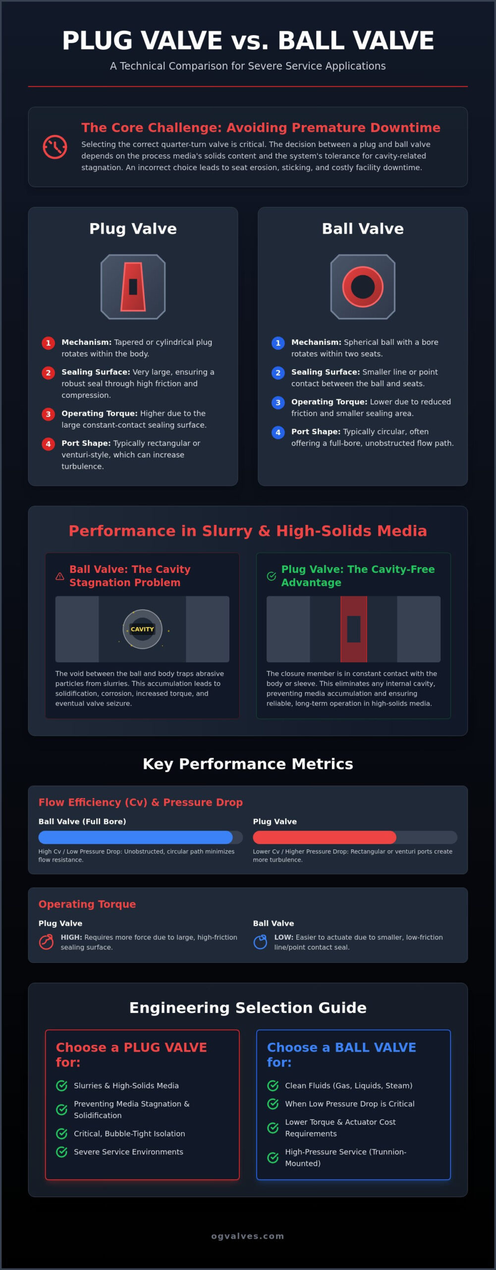
Selecting a quarter-turn isolation component based on historical preference rather than precise media rheology remains a primary cause of premature facility downtime. While both designs provide rapid shut-off, the engineering decision between a plug valve vs ball valve is dictated by the solids content of the process media and the system tolerance for cavity-related stagnation. You likely recognize the operational strain caused by premature seat erosion in ball valves or the torque-related sticking issues common in non-lubricated plug designs.
This technical analysis provides an authoritative comparison of these two valve architectures, evaluating their performance thresholds and adherence to API 599 and API 6D standards. We examine the structural mechanics that define seal integrity and investigate fugitive emission mitigation strategies required for compliance with EN ISO 15848-3 regulations effective as of January 2025. By reviewing quantifiable data on seat design and flow coefficients, we establish a framework for optimizing Mean Time Between Failure (MTBF) in critical industrial infrastructure. This guide serves as a technical justification for procurement specialists and engineers tasked with maintaining long-term operational output in severe service environments.
Key Takeaways
- Identify the mechanical advantages of tapered plug versus spherical ball geometries to optimize port configurations for specific industrial flow requirements.
- Evaluate the performance of a plug valve vs ball valve in high-solids media, focusing on how cavity-free designs mitigate stagnation and prevent premature seat erosion.
- Analyze maintenance protocols and sealing integrity, comparing the self-cleaning action of plug valves with the low-torque operational benefits of ball valve designs.
- Assess flow efficiency by comparing pressure drop data and flow coefficients (Cv) to ensure compliance with system-wide performance thresholds.
- Apply rigorous selection criteria based on ASME B16.34 and API standards to align material classifications with media viscosity, corrosivity, and pressure ratings.
Design Fundamentals: Tapered Plug vs Spherical Ball Geometry
The primary distinction in the plug valve vs ball valve debate begins with the physical geometry of the closure member. A plug valve utilizes a tapered or cylindrical cone that rotates within the valve body to control flow. In contrast, a ball valve employs a spherical disc with a bored-through hole. Both designs utilize quarter-turn actuation, allowing for rapid shut-off, yet their mechanical performance under high-pressure conditions differs significantly due to their respective contact surfaces. While they share similar speed of operation, the torque required to break the seal in a plug valve is typically higher because of the total surface contact between the plug and the body.
The plug valve provides a significantly larger sealing surface area than the ball valve. This design feature ensures a robust, bubble-tight seal through friction and compression. Because the plug remains in constant contact with the body or sleeve, it’s less susceptible to seat bypass in high-solids applications. However, this increased surface area results in higher operating torque compared to the point-contact or line-contact characteristic of most ball valve design fundamentals. Engineers must account for these torque variations when sizing actuators for critical isolation points.
The Plug Valve Mechanism
The tapered plug creates a seal by being wedged into the valve body. In lubricated designs, sealant is injected under pressure to reduce friction and provide a secondary seal. Non-lubricated variants utilize a sleeve, typically PTFE, to achieve isolation without external maintenance. Expanding plug designs use a mechanical wedge to press seating segments against the body, eliminating wear during rotation. The rectangular port shape in most plug valves creates a non-linear flow path. This geometry can increase turbulence and pressure drop compared to the circular bores found in ball valves, requiring careful consideration of flow dynamics during the specification phase.
The Ball Valve Mechanism
Ball valves are categorized primarily by how the ball is supported within the housing. Floating designs rely on upstream pressure to push the ball against the downstream seat, which is effective for lower pressure ranges. For high-pressure industrial isolation, trunnion-mounted designs are superior. They secure the ball at the top and bottom, which reduces torque and prevents seat deformation under load. Soft seats provide excellent low-pressure sealing, while metal seats are required for abrasive or high-temperature service. For a detailed breakdown of these components, consult our Industrial Ball Valves: A Technical Engineering & Specification Guide. In the plug valve vs ball valve comparison, ball valves more commonly offer a true full-bore circular path, whereas plug valves often feature a venturi-style port that requires precise engineering to match system flow requirements.
In heavy industrial sectors like chemical processing and mineral extraction, the choice between a plug valve vs ball valve is frequently decided by the media’s particulate concentration. Standard ball valves feature a central cavity between the ball and the valve body. When the valve is in the open position, this space remains exposed to the process fluid. For slurries or high-solids media, this results in the entrapment of abrasive particles within the body. These particles settle, dewater, and eventually solidify, leading to a significant increase in actuation torque or total valve seizure.
The Cavity Stagnation Problem
The accumulation of media within the ball cavity creates a localized environment for corrosion and mechanical obstruction. If the process fluid is prone to crystallization or carries high-viscosity solids, the dead space becomes a primary failure point. A cavity-free design is a critical requirement for slurry service to prevent the accumulation of solids within the valve body. Plug valves address this through a design where the closure member remains in constant contact with the seating surface or sleeve. There’s no internal cavity for media to occupy. This architectural difference ensures that the plug valve vs ball valve selection remains a primary consideration for engineers managing tailings, pulp, or catalyst-laden flows.
Erosion and Trim Wear
Erosion patterns in isolation valves are most severe during the transition between the open and closed states. As a ball valve begins to close, the high-velocity flow is concentrated across a small area of the seat, leading to rapid impingement and seat degradation. Plug valves mitigate this through a self-cleaning wiping action. The rotation of the plug against the sleeve or body clears away scale and debris during each cycle, protecting the primary sealing surfaces from abrasive buildup. For systems requiring ball valves in abrasive service, hard-facing materials like Stellite or tungsten carbide are mandatory to resist trim wear. For a detailed analysis of material classifications and performance thresholds, engineers should refer to Industrial Valves: The Engineer’s Comprehensive Guide to Selection and Standards (2026).
When specifying components for petrochemical applications involving abrasive catalysts, metallurgical integrity is paramount. While ball valves offer superior flow coefficients in clean service, the plug valve’s ability to maintain seal integrity in “dirty” environments often justifies its higher initial torque requirements. If you’re currently evaluating specifications for high-solids infrastructure, you can review our technical inventory of plug valves at OG VALVES LTD. to ensure your selection meets API 599 requirements for severe service isolation.
Sealing Integrity and Maintenance Requirements
In the technical evaluation of a plug valve vs ball valve, sealing integrity remains the primary metric for long-term reliability. While ball valves are frequently marketed as maintenance-free, their Mean Time Between Failure (MTBF) in high-cycle service is often lower than that of a properly maintained plug valve. The inherent design of the tapered plug allows for the injection of emergency sealant. This provides a secondary barrier that most ball valves lack. In critical infrastructure, the ability to restore a seal without facility shutdown is a significant operational advantage. However, this reliability requires a disciplined maintenance schedule that many modern facilities seek to avoid.
Lubricated vs Non-Lubricated Plugs
Lubricated plug valves remain the gold standard for high-pressure gas isolation due to their ability to maintain a bubble-tight seal under extreme conditions. The sealant acts as a renewable structural component, filling microscopic voids and reducing the torque required for actuation. Industrial plug valves in standard service typically require lubrication every 50 to 100 cycles or on a quarterly basis to maintain optimal sealing performance. While non-lubricated plugs utilize PTFE or ceramic sleeves to reduce maintenance, they cannot match the pressure-assisted sealing capabilities of lubricated models in severe service environments.
Ball Valve Seat Failure Modes
Standard ball valves rely on soft seats, typically made of fluoropolymers, which are susceptible to thermal expansion and cold flow. When temperatures fluctuate, the volumetric change in the seat material can lead to increased torque or total leakage. To mitigate this, high-specification applications are transitioning to metal-seated ball valves. These components require precise engineering to ensure the ball and seat maintain contact without galling. Managing the high torque associated with metal-to-metal contact often necessitates advanced automation. For detailed specifications on managing these loads, refer to our guide on Industrial Valve Actuators: A Technical Guide to Automation and Control.
Fugitive emissions at the stem seal represent a critical risk for both designs. Compliance with EN ISO 15848-3 Class AQ is now mandatory for all industrial valves sold in the EU market as of January 2025. Plug valves often feature a simpler stem seal arrangement that is easier to pack for high-pressure service. Conversely, ball valves require sophisticated packing sets to prevent leakage during the high-velocity rotation of the stem. Engineers must weigh the plug valve vs ball valve selection against these regulatory benchmarks to ensure environmental safety and operational continuity.
Comparative Analysis of Pressure Drop and Flow Coefficient (Cv)
The hydraulic efficiency of an industrial piping system is fundamentally impacted by the internal geometry of its isolation components. In a plug valve vs ball valve comparison, the ball valve demonstrates superior flow coefficients (Cv) when configured in a full-bore design. Because the internal diameter of a full-bore ball valve matches the pipeline’s internal diameter exactly, it creates negligible resistance to the flow stream. This minimizes pressure drop and reduces the long-term energy requirements of the pumping system. Conversely, plug valves typically utilize a rectangular or venturi port. This transition from a circular pipe to a non-circular port causes a contraction of the flow stream, resulting in higher permanent pressure loss across the valve body.
Pressure Drop and Pumping Costs
Quantifying energy loss is essential for large-scale infrastructure where minor pressure drops translate into significant operational expenses. Reduced-port plug valves often present a flow area that is approximately 60% to 70% of the pipe’s cross-section. This restriction increases fluid velocity and the friction factor within the valve. Engineers must prioritize high Cv ball valves for long-distance transport lines where maintaining line pressure is critical. If the application involves high isolation integrity for hazardous media, the increased pumping costs associated with plug valves are often a necessary trade-off for safety. Calculating pressure recovery requires an analysis of the valve’s recovery factor (Fl), which is generally lower for plug designs due to their complex internal flow paths.
Port Geometry and Turbulence
The transition from a circular pipeline to the rectangular port of a plug valve induces significant turbulence. This disruption in the laminar flow profile increases the risk of cavitation in liquid service and aerodynamic noise in high-pressure gas applications. The non-circular port geometry fundamentally reduces the flow coefficient by creating secondary flow patterns and eddy currents at the port edges. In gas let-down stations, this turbulence leads to vibration-induced fatigue in downstream piping. While ball valves provide a smoother transition, they remain susceptible to cavitation damage on the downstream seat during the opening and closing cycles. For precise sizing and selection, you can consult our technical data on ball valves to compare Cv ratings against specific system requirements.
Sizing considerations for gas versus liquid media further differentiate these designs. Gas applications often tolerate the rectangular port of a plug valve better than high-velocity liquid systems, where the risk of water hammer and cavitation is more pronounced. Engineers must evaluate the specific gravity and viscosity of the media before finalizing the plug valve vs ball valve specification. In systems where flow efficiency is the primary performance metric, the ball valve remains the technically superior choice.
Engineering Specification: Selecting the Optimal Isolation Valve
The technical selection between a plug valve vs ball valve requires a structured engineering framework to ensure system integrity and regulatory adherence. This process begins with a comprehensive media characterization. Engineers must quantify solids content, fluid viscosity, and chemical corrosivity to determine if a cavity-free plug design or a high-flow ball valve is required. Pressure and temperature ratings must then be defined according to ASME B16.34 standards. This ensures the valve body and trim materials can withstand operational extremes without structural deformation or seal failure.
Operational frequency and maintenance accessibility are equally critical factors. High-cycle applications often favor ball valves due to lower torque requirements and reduced actuator sizing, whereas static isolation in abrasive service typically justifies the use of a plug valve. Finalizing the specification involves confirming compliance with API 6D for pipeline ball valves or API 599 for lubricated plug valves. Material compatibility must be verified against the process fluid, and fire-safe certifications such as API 607 are mandatory for valves in hydrocarbon service to maintain safety during thermal events.
Regulatory Standards and Certification
Adherence to international standards provides the primary validation for industrial valve performance. API 6D governs the design and testing of pipeline ball valves, ensuring they meet the rigorous demands of long-distance transport and pipeline pigging. For lubricated plug valves, API 599 specifies the design and manufacturing requirements necessary for high-pressure isolation and sealant injection capabilities. In sour service environments where hydrogen sulfide is present, all components must comply with NACE MR0175/ISO 15156 to prevent sulfide stress cracking and ensure metallurgical stability under chemical load.
Procurement and Global Supply Chain
Procuring high-specification valves for critical infrastructure demands rigorous quality control throughout the supply chain. Positive Material Identification (PMI) is a mandatory protocol to verify that the chemical composition of the valve body and trim matches the original material test reports. OG VALVES LTD. ensures full metallurgical compliance for global heavy industry projects by conducting comprehensive project management and supply chain audits. Every unit undergoes shell and seat hydro-testing according to API 598 protocols to verify zero-leakage performance before dispatch. This systematic approach to quality assurance minimizes the risk of facility downtime and ensures that the plug valve vs ball valve selection delivers the expected MTBF in severe service applications.
Optimizing Facility MTBF Through Precise Valve Specification
The technical distinction in the plug valve vs ball valve evaluation hinges on the specific operational environment and the media’s particulate concentration. While ball valves provide superior flow coefficients for clean service, the cavity-free architecture of the plug valve is essential for preventing media stagnation in high-solids applications. Adherence to ASME B16.34 and API standards remains the primary safeguard against premature component failure and fugitive emissions in critical infrastructure.
Identifying the optimal isolation solution requires a rigorous analysis of pressure-temperature ratings and material compatibility. OG VALVES LTD. maintains an extensive inventory of API 6D and API 599 compliant valves, supported by technical expertise for high-pressure and corrosive environments. Our global logistics network facilitates fast-track delivery to minimize facility downtime and sustain operational output across diverse industrial sectors. Contact OG VALVES LTD. for Technical Specification and Global Supply of Industrial Ball and Plug Valves to ensure your facility meets the highest benchmarks of industrial safety and engineering excellence.
Frequently Asked Questions
When is a plug valve preferred over a ball valve?
A plug valve is preferred for applications involving high-solids media or abrasive slurries where cavity stagnation in a ball valve would lead to component seizure. The decision between a plug valve vs ball valve is often determined by the presence of particulates in the process stream. The plug design provides a total sealing surface contact that is more robust in “dirty” environments, while also serving as a critical safety requirement for high-pressure gas isolation.
Do ball valves provide better sealing than plug valves?
Ball valves provide excellent isolation in clean, low-viscosity service through line-contact or point-contact seating. However, a plug valve offers superior sealing integrity in severe service because the entire plug surface remains in contact with the body or sleeve. The ability to inject secondary sealant into a lubricated plug design provides a redundant barrier that most ball designs cannot replicate, ensuring bubble-tight shut-off in high-pressure gas applications.
Why are plug valves used in slurry service?
Plug valves are utilized in slurry service because their cavity-free design prevents the entrapment and solidification of abrasive particles within the valve body. Unlike ball valves, which possess a dead space between the ball and housing, the plug’s continuous contact surface wipes away debris during rotation. This mechanical action ensures consistent actuation torque and prevents the internal erosion common in high-solids media, maintaining long-term operational output.
What are the main maintenance issues with plug valves?
The primary maintenance requirement for lubricated plug valves is the periodic injection of sealant to maintain seal integrity and reduce operating torque. Failure to adhere to lubrication intervals can lead to the plug sticking or increased wear on the seating surfaces. Non-lubricated variants may experience sleeve degradation over time, requiring replacement to prevent bypass leakage or stem emissions, particularly in high-temperature or corrosive chemical environments.
Can ball valves be used for throttling flow?
Standard ball valves are designed for on-off isolation and are generally unsuitable for throttling applications. Operating a ball valve in a partially open position concentrates high-velocity flow across a limited area of the seat, leading to rapid impingement and permanent seal damage. For precise flow control, engineers should specify dedicated control valves rather than adapting quarter-turn isolation components, as throttling significantly reduces the valve’s Mean Time Between Failure.
What API standards govern industrial plug valves?
The American Petroleum Institute governs industrial plug valves primarily through API 599, which covers design, materials, and testing for metal plug valves. For pipeline-specific applications, API 6D requirements ensure the component meets the structural demands of long-distance transport. Additionally, API 598 defines the mandatory hydro-testing protocols for verifying shell and seat integrity before facility installation, while API 607 provides the benchmark for fire-safe performance.
Is a trunnion-mounted ball valve better than a plug valve for high pressure?
A trunnion-mounted ball valve is technically superior for high-pressure clean service because it manages mechanical loads through fixed supports, reducing operating torque. For high-pressure slurries or abrasive media, the plug valve remains the preferred selection due to its lack of internal cavities. The final selection of a plug valve vs ball valve for high-pressure service must align with the system’s tolerance for internal cavities and the metallurgical requirements of the media.
 Responsive Menu