An imprecise pressure drop calculation across a valve isn’t just a mathematical oversight; it’s a direct precursor to catastrophic component failure and systemic energy waste. Engineering teams in the petrochemical and power generation sectors frequently navigate the volatility of fluid properties and the rigorous demands of API or ASME standards. You recognize that even a minor deviation in differential pressure can trigger destructive cavitation, erode valve seats, and inflate operational costs through excessive head loss. These technical inaccuracies compromise the structural soundness of critical infrastructure and lead to unplanned downtime.
This technical guide provides a definitive framework for performing these calculations with absolute precision. You’ll master the application of flow coefficients (Cv) and ensure your system’s adherence to global industrial benchmarks for safety and efficiency. We’ll examine the fundamental physics of fluid dynamics, evaluate the variables affecting specific architectures like gate and globe valves, and establish a repeatable methodology for optimizing your high-specification components. By the conclusion, you’ll possess the data-driven insights necessary to select valves that minimize energy loss while maintaining maximum operational output.
Key Takeaways
- Identify the conversion of mechanical energy into heat caused by systemic friction and turbulence to define the precise loss in total pressure.
- Establish a clinical, repeatable workflow for pressure drop calculation across a valve using laboratory-tested flow coefficients (Cv).
- Analyze the trade-offs between throttling capability and pressure recovery across various architectures, including globe, gate, and ball valves.
- Don’t apply standard turbulent flow formulas to non-ideal conditions involving high-viscosity fluids or cavitation risks without proper correction factors.
- Ensure compliance with API and ASME standards to balance initial procurement costs with long-term energy efficiency and component longevity.
The Physics of Differential Pressure (ΔP) in Industrial Systems
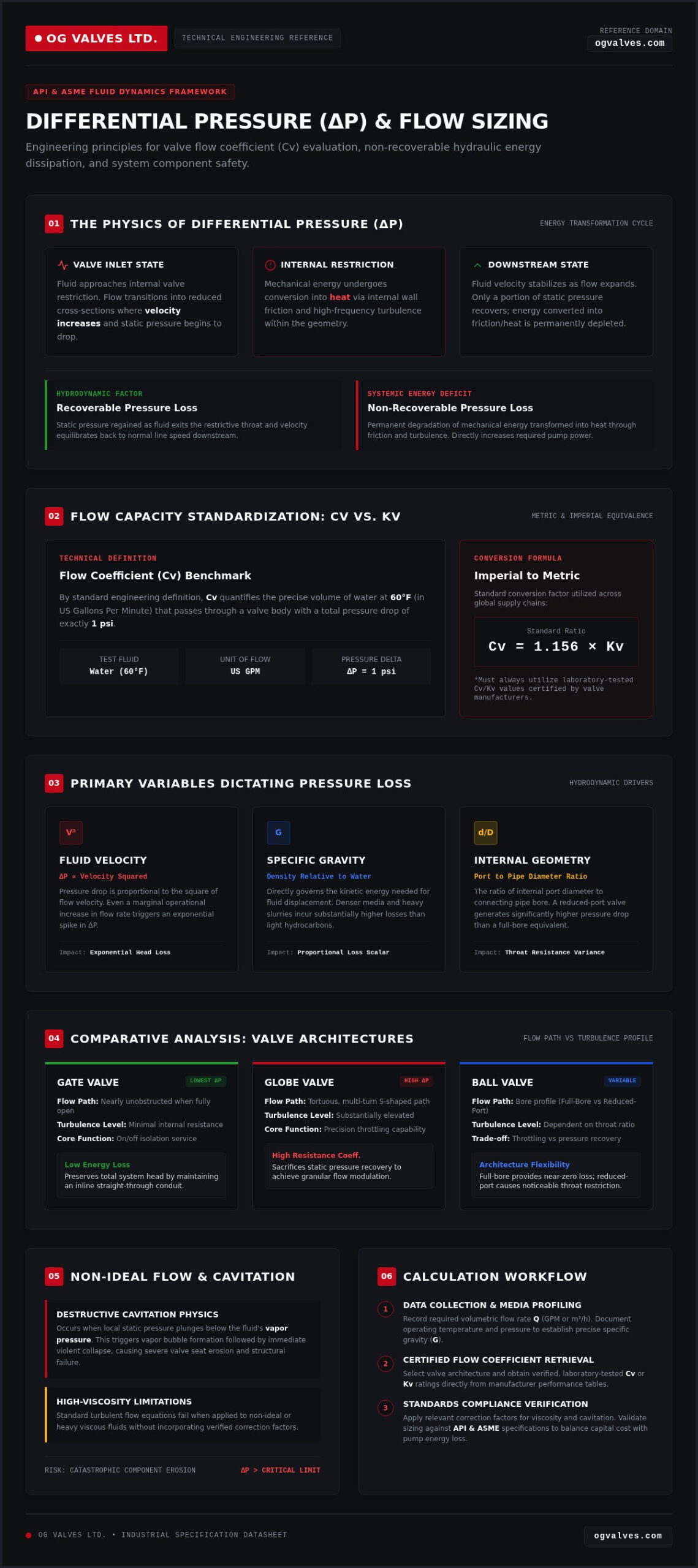
Pressure drop represents the quantifiable degradation of total pressure as fluid traverses internal valve geometries. In any closed-loop industrial system, this differential pressure (ΔP) occurs because the valve acts as a restriction. As fluid enters the valve body, its velocity increases while its static pressure decreases. This transition isn’t merely a change in state; it’s an energy conversion process. The mechanical energy of the fluid is partially transformed into heat through internal friction against the valve walls and the high-frequency turbulence generated by the flow path. Performing a precise pressure drop calculation across a valve requires a fundamental understanding of these energy states to prevent system-wide inefficiencies.
Internal resistance is dictated by the valve’s specific architecture. For instance, a gate valve provides a nearly unobstructed flow path when fully open, resulting in minimal turbulence. Conversely, a globe valve forces the fluid through a tortuous, S-shaped path, significantly increasing the resistance coefficient. It’s critical to distinguish between recoverable and non-recoverable pressure loss. While some static pressure is regained downstream as fluid velocity stabilizes, the energy lost to heat and turbulence is permanent. This non-recoverable loss directly impacts the pump power required to maintain the desired flow rate.
The Role of the Flow Coefficient (Cv)
The flow coefficient, or Cv, is the primary metric used to quantify a valve’s capacity. By definition, Cv represents the volume of 60°F water in US gallons per minute that will pass through a valve with a pressure drop of 1 psi. It provides a clinical, standardized basis for comparing the efficiency of different valve types under identical operating conditions. This relationship is the cornerstone of any pressure drop calculation across a valve intended for high-stakes industrial applications. In international contexts, engineers frequently utilize the metric equivalent, Kv. To ensure calculation accuracy across global supply chains, use the standard conversion factor: Cv = 1.156 * Kv. Relying on verified, laboratory-tested Cv values from manufacturers is essential for maintaining regulatory adherence and operational safety.
Variables Influencing Pressure Loss
Several physical properties of the process medium and the hardware itself dictate the magnitude of pressure loss. These variables must be accounted for with technical precision:
- Fluid Velocity: Pressure drop is proportional to the square of the flow velocity. Even a marginal increase in flow rate can lead to an exponential spike in ΔP.
- Specific Gravity: The density of the fluid relative to water directly affects the energy required to move it. Heavier fluids or slurries incur higher losses than light hydrocarbons.
- Internal Geometry: The ratio of the valve’s internal port diameter to the connecting pipe size is a critical determinant. A reduced-port valve will naturally generate a higher pressure drop than a full-bore equivalent due to the increased restriction at the throat.
Failure to account for these variables results in inaccurate sizing. This often leads to cavitation, where the local pressure drops below the fluid’s vapor pressure, causing the formation and violent collapse of vapor bubbles that can destroy internal components.
Step-by-Step Procedure for Pressure Drop Calculation
Engineers must implement a clinical, repeatable workflow to ensure the integrity of industrial piping systems. A standard pressure drop calculation across a valve requires precise input data to yield reliable results. Inconsistent units or reliance on generic estimates rather than manufacturer-provided Cv values will compromise system efficiency and safety benchmarks. Maintaining technical precision throughout this process is a non-negotiable requirement for compliance with API and ASME standards.
Step 1: Data Collection and Fluid Identification
Success begins with rigorous data collection. Identify the required flow rate (Q) in gallons per minute (GPM) or cubic meters per hour (m³/h). It’s essential to document the process temperature and pressure to determine the fluid’s specific gravity (G) at actual operating conditions. Once the fluid properties are established, select the target valve architecture and retrieve its laboratory-tested Cv or Kv rating from the manufacturer’s technical specifications. If you’re working with high-specification environments, ensure these values are verified through rigorous testing protocols.
Step 2: Applying the Standard Flow Equation
For liquid applications, apply the fundamental flow equation: ΔP = G * (Q / Cv)². This formula calculates the differential pressure in pounds per square inch (psi). Understanding the specific nuances of the valve flow coefficient is vital during this stage. While the liquid formula is straightforward, gas and steam applications require modified equations to account for fluid compressibility and expansion factors. For compressible fluids, engineers must calculate the pressure drop ratio (ΔP/P1). If this ratio is high, the fluid density changes significantly as it passes through the valve, necessitating more complex mathematical models to maintain accuracy in your pressure drop calculation across a valve.
Step 3: Verification Against System Limits
The final stage involves comparing the calculated ΔP against the total available system head. If the pressure drop is excessive, it may indicate that the selected valve is undersized, which will lead to increased energy expenditure and potential pump cavitation. For control valve applications, a reliable engineering benchmark is to ensure the pressure drop doesn’t exceed 10% to 15% of the absolute inlet pressure. In gas service, you must check for choked flow conditions. When the downstream pressure falls below approximately 50% of the upstream pressure, the flow velocity reaches sonic levels, and further increases in ΔP won’t increase the flow rate. Consulting with a technical partner for high-specification valve selection ensures that your calculations align with the functional reality of your critical infrastructure.
Comparative Analysis: Pressure Drop by Valve Architecture
The internal geometry of a valve is the primary physical constraint governing the resistance coefficient (K). This dimensionless value represents the pressure head loss in terms of velocity heads. A precise pressure drop calculation across a valve must account for these architectural variances, as they dictate the transition from static to dynamic pressure. While some designs prioritize unobstructed flow to conserve energy, others intentionally introduce resistance to provide superior modulation and shutoff capabilities. For a broader overview of these specifications, consult our guide on industrial valves.
Low-Resistance Valves: Gate and Ball
Designers seeking to minimize parasitic energy loss typically specify gate valves for on/off service. These components utilize a linear motion wedge that, when fully retracted, provides a straight-through flow path matching the pipe’s internal diameter. This results in K factors as low as 0.1, ensuring negligible turbulence. Similarly, a full-port ball valve functions as a near-zero drop solution. It’s essentially a continuation of the piping itself. However, engineers must account for “venturi” or reduced-port designs. These variations introduce sudden contractions and expansions in the flow stream, which can significantly elevate the ΔP compared to full-bore equivalents.
High-Resistance Valves: Globe and Check
Conversely, the tortuous internal path of a globe valve is engineered for precision throttling rather than flow efficiency. Fluid must undergo two 90-degree turns and pass through a restrictive seat area, creating high-intensity turbulence and a high K factor. This architecture is essential for control applications where high ΔP is a functional requirement. Additionally, check valves introduce a unique pressure drop penalty. A specific “cracking pressure” is required to overcome the gravitational or spring force acting on the disc to maintain an open position. If the flow velocity is insufficient to fully lift the disc, the valve will operate in a partially open state, further increasing the resistance. Integrating these architectural realities into your pressure drop calculation across a valve is critical for maintaining system integrity and avoiding premature component wear.
Accounting for Non-Ideal Flow: Viscosity and Cavitation
The standard Cv equation serves as a baseline, but its application in high-stakes industrial environments requires critical adjustments. Most standard formulas assume turbulent flow and low-viscosity liquids, a scenario that doesn’t reflect the reality of heavy crude oil, complex chemical polymers, or volatile petrochemical mediums. Ignoring these non-ideal properties during a pressure drop calculation across a valve leads to significant sizing errors. These inaccuracies don’t just reduce efficiency; they represent a high cost of failure in terms of component erosion and systemic safety risks.
Viscosity Correction Factors
Reynolds number (Re) is the primary criterion for identifying the flow regime within a piping system. When handling viscous fluids, the flow often shifts from turbulent to transitional or laminar states. In these conditions, the Viscosity Correction Factor (Fv) must be applied to the calculated Cv. If the Reynolds number falls below 10,000, the standard square-root relationship between flow and pressure drop becomes increasingly inaccurate. Engineers must calculate the valve Reynolds number (Rev) using the specific internal geometry and fluid viscosity. This data-driven adjustment ensures the valve isn’t undersized, preventing the excessive head loss that occurs in high-resistance media.
Cavitation and Flashing Risks
Cavitation occurs when the localized pressure at the “vena contracta”, the point of minimum area and maximum velocity within the valve, drops below the fluid’s vapor pressure. Vapor bubbles form and then collapse violently as the pressure recovers downstream. This process releases concentrated energy that can pit and destroy even the most durable material classifications. The pressure recovery factor (Fl) is an essential metric here. It quantifies a valve’s ability to convert kinetic energy back into static pressure. High-recovery valves, such as ball or butterfly designs, are generally more susceptible to cavitation than low-recovery architectures like globe valves.
To prevent catastrophic failure in volatile services, engineers utilize specialized valve trims or implement multistage pressure drops. These strategies dissipate energy gradually, ensuring the vena contracta pressure remains above the vapor threshold. For projects requiring high-specification components that meet rigorous API and ASME standards, you should source valves with verified laboratory-tested Cv data to ensure long-term operational output. Maintaining this level of technical precision is the only way to guarantee structural soundness in critical infrastructure.
Strategic Valve Specification for System Integrity
Strategic procurement requires a shift from evaluating initial capital expenditure (CAPEX) to analyzing total lifecycle costs. A pressure drop calculation across a valve isn’t merely a design step; it’s a financial projection. High differential pressure necessitates increased pump output, which translates directly into elevated annual energy consumption. For continuous processes in the petrochemical sector, the cost of overcoming parasitic head loss can exceed the valve’s purchase price within months of operation. Engineers must prioritize architectures that offer the highest flow capacity relative to their footprint to ensure long-term profitability.
Optimizing Valve Selection for Energy Efficiency
In large-diameter infrastructure, selecting the appropriate architecture is vital for minimizing systemic resistance. Upgrading to high-performance butterfly valves often provides the optimal balance of high Cv and low weight for lines exceeding 12 inches. Beyond initial selection, material integrity plays a decisive role in maintaining flow efficiency. Corrosion or abrasive wear alters the internal surface finish and port geometry, which shifts the valve’s resistance coefficient over time. Sourcing components with superior metallurgical classifications ensures that the laboratory-tested Cv remains consistent throughout the asset’s service life, preventing unexpected energy spikes and unplanned maintenance cycles.
Ensuring Compliance with ASTM and API Standards
Regulatory adherence is the primary form of brand validation for critical infrastructure. In high-pressure or hazardous services, material certifications and Positive Material Identification (PMI) testing are non-negotiable requirements. OG VALVES LTD. operates as a technical partner rather than a mere vendor, ensuring every component meets the rigorous demands of the global energy sector. We anchor our claims in rigorous quality control processes, providing technical experts with the verifiable data needed for a precise pressure drop calculation across a valve. This commitment to engineering excellence protects system integrity and mitigates the risk of catastrophic failure in high-stakes environments.
Our global logistics network and fast-track delivery capabilities support the maintenance of critical infrastructure without compromising on technical specifications. For large-scale projects requiring deep industrial expertise, we provide comprehensive technical consultations to optimize component selection. Request a technical quote for your industrial valve requirements to ensure your system meets the highest benchmarks for safety and operational output.
Executing a rigorous pressure drop calculation across a valve ensures that every component operates within its designed mechanical limits. This methodology prevents the systemic risks of cavitation and excessive energy consumption while maintaining the structural soundness required for high-stakes industrial environments. By prioritizing laboratory-verified flow coefficients and accounting for non-ideal fluid properties, engineers secure the long-term operational output of their critical infrastructure. Adherence to API 600 and ASME standards remains the benchmark for safety and regulatory compliance in the global energy sector.
OG VALVES LTD. provides the technical expertise necessary to bridge the gap between complex fluid dynamics and functional reality. We offer global fast-track delivery of gate, ball, and globe valves, backed by expert technical support for heavy industry applications. Our commitment to industrial precision ensures you don’t compromise on safety or lifecycle performance. Consult with OG VALVES LTD. for High-Specification Industrial Valve Procurement to ensure your next installation achieves maximum efficiency and unwavering reliability.
Frequently Asked Questions
What is the difference between Cv and Kv in pressure drop calculations?
Cv and Kv are the two primary metrics used to define valve capacity, differing only in their units of measurement and reference conditions. Cv represents the volume of 60°F water in US gallons per minute that generates a 1 psi drop. Kv is the metric equivalent, defined as the flow in cubic meters per hour with a 1 bar pressure drop. For an accurate pressure drop calculation across a valve, engineers must apply the conversion factor Cv = 1.156 * Kv to maintain consistency across international technical specifications.
How does fluid viscosity affect the accuracy of a valve pressure drop calculation?
Standard flow equations assume a fully turbulent flow regime, which is not the case for high-viscosity fluids. As viscosity increases, the Reynolds number decreases, potentially shifting the flow into transitional or laminar states. This shift requires the application of a Viscosity Correction Factor (Fv) to the standard Cv. Failure to account for these viscous effects results in an undersized valve, leading to excessive head loss and reduced operational output in petrochemical or heavy oil applications.
Can I calculate pressure drop for gases using the same formula as liquids?
You cannot use the liquid flow equation for gas or steam because these fluids are compressible. Unlike liquids, gas density changes significantly as it passes through the valve restriction. A pressure drop calculation across a valve in gas service requires modified formulas that incorporate expansion factors and the ratio of specific heats. If the pressure drop exceeds 50% of the inlet pressure, the flow becomes choked, a condition where velocity reaches sonic levels and the standard liquid formulas fail completely.
What is a ‘safe’ pressure drop for an industrial isolation valve?
For an industrial isolation valve, such as a full-bore ball or gate valve, the target pressure drop should be as close to zero as possible. These components are designed to provide an unobstructed flow path. In most high-specification piping systems, a drop exceeding 1 to 2 psi across a fully open isolation valve indicates a sizing error or internal blockage. Conversely, control valves are engineered to handle much higher drops, typically between 10% and 15% of the total system pressure.
How do I account for pipe reducers when calculating valve pressure drop?
Pipe reducers and expanders introduce additional turbulence and friction that are not accounted for in a valve’s base Cv rating. When the valve size is smaller than the line size, engineers must calculate a Piping Geometry Factor (Fp). This factor adjusts the effective Cv to account for the pressure losses at the transitions. Neglecting these geometry effects leads to an overestimation of the valve’s actual capacity, which compromises the accuracy of the final pressure drop results in critical infrastructure projects.
What happens to the pressure drop if a valve is only partially open?
When a valve is partially open, its effective Cv decreases significantly, causing the pressure drop to increase exponentially. This occurs because the internal flow path becomes more restricted, increasing both friction and turbulence. In globe or needle valves, this relationship is often linear or equal-percentage, depending on the trim design. However, using isolation valves like gate or ball valves in a partially open state is discouraged; it causes high-velocity erosion and vibration that threatens component longevity.
Why is cavitation more common in valves with high pressure recovery?
Cavitation is more prevalent in high-pressure recovery valves, such as ball or butterfly types, because they have a low pressure recovery factor (Fl). These valves allow the fluid velocity to spike significantly at the vena contracta, causing a deep localized pressure drop. If this pressure falls below the fluid’s vapor pressure, vapor bubbles form. While these valves regain static pressure quickly downstream, the violent collapse of those bubbles against the internal surfaces causes severe pitting and material failure.
How does temperature affect specific gravity in ΔP calculations?
Specific gravity (SG) is a temperature-dependent variable that directly impacts the density of the process medium. As temperature increases, most industrial fluids expand, which lowers their specific gravity. Since the pressure drop is directly proportional to the SG, using a value based on ambient conditions for a high-temperature process will result in an overestimation of the ΔP. Engineers must utilize the SG at the actual operating temperature to ensure the structural soundness and efficiency of the valve selection.
 Responsive Menu