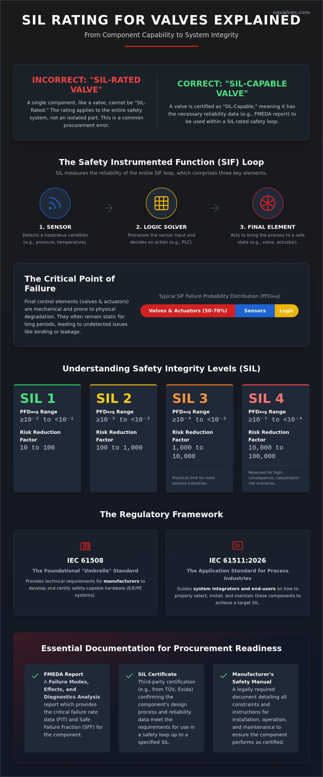
A valve, in isolation, cannot possess a Safety Integrity Level (SIL) rating. While procurement specifications often demand SIL-rated hardware, this terminology is technically inaccurate under the foundational standards of functional safety. This guide provides a clinical SIL rating for valves explained within the context of the entire Safety Instrumented Function (SIF). It’s common to feel frustrated by the complexities of IEC 61508 and the recently updated IEC 61511:2026, especially when you’re tasked with bridging the gap between component-level failure data and system-level compliance. You’re likely navigating the pressure of calculating Probability of Failure on Demand (PFD) for final control elements while ensuring your documentation satisfies rigorous third-party audits.
This analysis clarifies the distinction between SIL-capable components and SIL-rated loops, ensuring your specifications for gate, ball, or butterfly valves meet the uncompromising demands of high-hazard environments. We’ll examine the specific requirements for IEC 61508:2010 compliance, the practical limits of SIL 3 applications, and the essential documentation required for safety-critical procurement. By the end of this technical guide, you’ll possess the framework necessary to specify final control elements that align with global engineering benchmarks and operational safety requirements.
Key Takeaways
- Differentiate between SIL-capable individual components and SIL-rated safety loops to ensure compliance with IEC 61511:2026 and ANSI/ISA 84 standards.
- Access a technical SIL rating for valves explained through the quantification of Probability of Failure on Demand (PFDavg) and Safe Failure Fraction (SFF).
- Analyze the impact of material selection and Positive Material Identification (PMI) on failure rates (FIT) within high-pressure or corrosive industrial environments.
- Identify the specific hardware fault tolerance (HFT) requirements necessary to achieve SIL 2 or SIL 3 targets in final control elements.
- Verify procurement readiness by identifying essential documentation, including FMEDA reports, SIL certificates, and manufacturer-issued Safety Manuals.
Safety Integrity Level (SIL) in Industrial Valve Systems
A Safety Integrity Level (SIL) is a quantifiable measurement of the risk reduction provided by a Safety Instrumented Function (SIF). It’s not a badge for a single piece of hardware. Instead, SIL represents the reliability of an entire loop, comprising sensors, logic solvers, and final control elements. To have a SIL rating for valves explained accurately, one must first recognize that the valve is a mechanical component within a broader electrical, electronic, or programmable electronic (E/E/PE) system. Standards categorize risk reduction into four discrete levels, from SIL 1 to SIL 4. Each level corresponds to a specific range of Average Probability of Failure on Demand (PFDavg). SIL 1 requires a PFDavg between 10^-1 and 10^-2, while SIL 3 demands a much lower probability between 10^-3 and 10^-4. SIL 3 remains the practical ceiling for most industrial applications; SIL 4 is reserved for specialized, high-consequence scenarios where the cost of failure is catastrophic.
The Regulatory Framework: IEC 61508 and IEC 61511
IEC 61508 serves as the foundational standard, providing the technical requirements for manufacturers to develop safety-capable hardware. It’s an umbrella standard that applies to all E/E/PE safety-related systems. In contrast, IEC 61511:2026 focuses on the application of these components within the process industry, specifically for integrators and end-users. A SIF represents the complete loop that detects a hazard, processes the logic, and actuates the final element to bring the process to a safe state. Safety Integrity Level is a statistical probability of a system performing its required function under stated conditions. This distinction is critical because hardware alone doesn’t guarantee safety; the integration and maintenance of the entire loop determine the final SIL achievement. Navigating a SIL rating for valves explained by manufacturers requires checking their data against these specific regulatory benchmarks.
Why Final Control Elements Are Critical
Valves and actuators represent the highest failure probability within a safety loop, often accounting for 50% to 70% of the total PFDavg. While sensors and logic solvers are electronic and often benefit from continuous self-diagnostic capabilities, valves are mechanical. They are subject to physical degradation from the process media, such as scaling, corrosion, or erosion. A Basic Process Control System (BPCS) handles active, continuous regulation to keep the process within set limits. A Safety Instrumented System (SIS), however, often remains static for months or years. This static state can lead to mechanical binding or seat leakage that goes undetected until a crisis. High-performance industrial valves must therefore meet stringent reliability data requirements to prove they will function precisely when a demand occurs. Failure at this final stage renders the entire safety loop useless, regardless of the sophistication of the upstream electronics.
The Final Control Element: Why Valves Are SIL-Capable, Not SIL-Rated
A pervasive industry misconception suggests that procurement specialists can simply purchase a “SIL-rated valve” as a standalone product. This terminology is technically incorrect. A valve is a mechanical sub-element. While it may be designed for high-integrity applications, the SIL rating applies exclusively to the completed Safety Instrumented Function (SIF). When we look at a SIL rating for valves explained through the lens of IEC 61508, we must use the term “SIL Capability.” This refers to the suitability of a component for use in a safety loop of a specific integrity level. Components are classified as either Type A or Type B. Valves are categorized as Type A components. These are simple mechanical devices with well-understood failure modes and no internal software or complex logic. This simplicity is an advantage in safety systems. Type A devices typically require less diagnostic coverage to achieve higher hardware fault tolerance (HFT) compared to Type B electronic devices like logic solvers.
Component Reliability vs. System Integrity
System integrity is a cumulative value. A valve’s role is defined by its specific failure rate data, denoted as λ (lambda). It’s a mistake to assume a SIL 3 capable valve automatically guarantees a SIL 3 loop. If the associated pressure transmitter or logic solver has a high probability of failure, the entire system’s integrity drops. Engineers must aggregate the failure data of every component in the loop to determine the final PFDavg. For those seeking high-reliability components, reviewing the technical specifications of specialized industrial valves is the first step in this calculation. This process ensures that the mechanical reliability of the final control element aligns with the electronic precision of the sensors and logic solvers.
FMEDA Reports and Certification
The primary document for verifying a component’s suitability is the Failure Modes, Effects, and Diagnostic Analysis (FMEDA) report. This technical document provides the precise failure rates, failure modes, and diagnostic coverage percentages required for SIF verification. Third-party certification bodies, such as exida or TUV, audit these reports to validate manufacturer claims. When engineers specify gate valves for SIS duty, they rely on the FMEDA to distinguish between safe failures and dangerous undetected failures. Adherence to these Functional Safety Standards ensures that mechanical elements provide the predictable performance necessary for critical infrastructure protection. This structured approach to a SIL rating for valves explained ensures that systematic failures are minimized through rigorous design and manufacturing protocols.
Quantifying Reliability: PFDavg, SFF, and Failure Rates (FIT)
The reliability of a Safety Instrumented Function (SIF) depends on quantifiable data. To have a SIL rating for valves explained, one must analyze three primary metrics: Average Probability of Failure on Demand (PFDavg), Safe Failure Fraction (SFF), and Failures in Time (FIT). FIT serves as the baseline unit of measure for failure rates. One FIT equals one failure per 10^9 hours of operation. In high-pressure or corrosive environments, the FIT rate for a mechanical component increases significantly. This degradation directly impacts the SFF, which is the ratio of safe failures and dangerous detected failures to the total failure rate. A higher SFF allows a system to achieve a specific SIL with lower hardware fault tolerance. It’s critical to realize that these metrics aren’t static; they fluctuate based on the specific industrial environment and the physical demands placed on the hardware.
Calculating PFDavg for Final Elements
PFDavg is the mean probability that a safety function will fail to perform when required. This value isn’t static. It’s a function of the component’s failure rate and the Proof Test Interval (PTI). The longer the duration between tests, the higher the PFDavg, which can degrade the loop’s integrity level. Operators often utilize Partial Stroke Testing (PST) to mitigate this risk. PST involves moving the valve stem a small percentage, perhaps 10% to 20%, to verify it isn’t stuck. This diagnostic increases the diagnostic coverage and improves the PFDavg without requiring a full process shutdown. For specialized applications, such as subsea safety valves, the PTI is often much longer due to accessibility issues, making high initial reliability and PST capability mandatory.
Hardware Fault Tolerance (HFT) and Redundancy
Hardware Fault Tolerance (HFT) defines the ability of a system to continue performing its safety function in the presence of one or more dangerous failures. An HFT of 0, typically a 1oo1 (one-out-of-one) configuration, means a single failure of the valve will result in a failure of the SIF. To achieve SIL 3 in many process environments, an HFT of 1 is required. This often involves a 1oo2 (one-out-of-two) architecture where two valves are installed in series. If one valve fails to close, the second provides the necessary isolation. This redundancy compensates for the mechanical limitations of individual components. Architectural constraints in IEC 61508 dictate these configurations based on the SFF of the chosen hardware. When the SIL rating for valves explained is applied to system design, these redundancies ensure that the target risk reduction factor is maintained throughout the operational lifecycle.
Mechanical Integrity and Material Selection for SIS Applications
Mechanical integrity constitutes the physical foundation of any statistical safety claim. While previous sections detailed the mathematical framework of SIL rating for valves explained, those calculations remain theoretical without rigorous material selection and environmental hardening. Corrosive or high-pressure environments act as catalysts for accelerated component degradation, which directly inflates the Failures in Time (FIT) rates. Positive Material Identification (PMI) is a mandatory protocol in safety-critical procurement. It ensures that the alloy composition of the valve body and trim matches the technical specifications required to resist specific chemical attacks. Discrepancies in material grade can lead to premature failure, rendering the initial FMEDA data invalid and compromising the safety loop.
Dangerous undetected (DU) failures often manifest as ‘stiction’ or seat leakage. Stiction occurs when a valve remains in a static position for extended periods, causing the packing or seals to bond with the stem or ball. This mechanical resistance can prevent the actuator from reaching the fail-safe position during a demand. For high-cycle or critical emergency shutdown (ESD) service, the selection of ball valves is standard practice. Their quarter-turn operation and high-integrity seating provide the rapid, reliable isolation necessary for SIS duty. If you require hardware that meets these uncompromising standards, you should explore our range of high-performance industrial valves designed for critical infrastructure.
Environmental Stress and Failure Modes
Temperature cycling and media abrasive properties represent significant threats to mechanical integrity. Stem shearing and seat erosion are specific failure modes that must be mapped to SIL data categories. If a valve stem shears due to material fatigue, the logic solver may indicate a successful actuation while the process remains un-isolated. This is the definition of a dangerous undetected failure. Non-Destructive Testing (NDT), including radiographic and ultrasonic examinations, is essential during the manufacturing phase to identify subsurface defects. These rigorous quality control measures ensure that the mechanical failure rates stay within the bounds defined by the safety lifecycle.
Actuator and Solenoid Integration
The final control element is a package, not just a valve body. When assessing a SIL rating for valves explained for a project, the actuator and solenoid must be included in the total PFDavg calculation. The solenoid valve response time is a critical variable in the total SIF reaction time. If the solenoid’s exhaust port is restricted or its coil fails, the valve cannot move to its fail-safe position. SIS design requires explicit fail-safe definitions: fail-closed, fail-open, or fail-last. Each component in this assembly must be certified for the target SIL to ensure that the cumulative reliability of the final control element meets the risk reduction requirements of the plant.
Specifying SIL-Capable Valves for Critical Infrastructure
Procuring safety-critical hardware requires a shift from standard vendor selection to rigorous technical auditing. To have a SIL rating for valves explained for procurement specialists, one must emphasize that the hardware is only as reliable as its supporting data package. Verification of a component’s suitability for a Safety Instrumented Function (SIF) requires three essential documents: the SIL certificate, the FMEDA report, and the Safety Manual. The SIL certificate provides a summary of the component’s capability, while the FMEDA report delivers the granular statistical failure rates required for PFDavg calculations. Full traceability remains a non-negotiable requirement. Material Test Reports (MTRs) must confirm that the chemical and mechanical properties of the valve body and trim align with the pressure and temperature variables defined in the safety specification. OG VALVES LTD. maintains these standards of engineering excellence to ensure that every final control element integrates seamlessly into high-integrity loops.
The Safety Manual and Installation Requirements
Under IEC 61508, a manufacturer is legally and technically mandated to provide a Safety Manual for any component intended for SIS duty. This document is not a standard installation guide; it defines the specific constraints on installation, maintenance, and mandatory proof testing intervals. These intervals are critical because they dictate the system’s ability to maintain its target PFDavg over the operational lifecycle. If maintenance personnel deviate from these instructions, the safety integrity of the entire loop is compromised. Suppliers also play a vital role in providing documented evidence of “Prior Use” or “Proven in Use” data. This historical performance data, governed by IEC 61511, serves as a benchmark for reliability when a component is used in environments that mirror previous successful applications.
Procuring for Minimal Downtime and Maximum Safety
Industrial facilities often face a conflict between high-specification safety requirements and project lead times. Achieving a SIL rating for valves explained in a project context involves balancing these technical demands without sacrificing structural soundness. OG VALVES LTD. functions as a technical partner rather than a mere vendor, ensuring that every component meets international regulatory benchmarks for functional safety. Our global supply chain capabilities and rigorous quality control processes allow for the delivery of certified hardware that supports both safety and operational output. For technical consultation on SIL-capable butterfly valves or other safety-critical components, contact OG VALVES LTD. today. We provide the quantifiable data and engineering precision necessary to protect critical infrastructure from the cost of failure.
Securing Operational Safety Through Rigorous SIL Compliance
Request a Technical Quote for SIL-Capable Industrial Valves today to align your infrastructure with global safety benchmarks.
Frequently Asked Questions
Can a valve be SIL 3 rated on its own?
A valve cannot be SIL 3 rated on its own because the Safety Integrity Level applies exclusively to the complete Safety Instrumented Function (SIF). It’s technically accurate to describe a valve as SIL 3 capable. This capability indicates that the component’s random failure rates and systematic design protocols are sufficient to meet the requirements of a SIL 3 loop when integrated with compliant sensors and logic solvers.
What is the difference between a SIL-capable valve and a SIL-certified valve?
SIL-capable refers to the inherent reliability of the hardware while SIL-certified indicates that a third-party body has validated the manufacturer’s claims. A certified valve has undergone a rigorous audit of its Failure Modes, Effects, and Diagnostic Analysis (FMEDA) by organizations like exida or TÜV. This third-party verification provides the high-stakes trust required for critical infrastructure projects where the SIL rating for valves explained in manufacturer catalogs must be backed by quantifiable data.
How does partial stroke testing (PST) affect a valve’s SIL rating?
Partial stroke testing (PST) improves the Average Probability of Failure on Demand (PFDavg) by increasing diagnostic coverage. It involves moving the valve stem a small percentage to ensure it isn’t seized. While PST doesn’t increase the component’s base capability, it allows operators to extend proof test intervals without degrading the loop’s safety integrity. This diagnostic tool identifies dangerous undetected failures before they result in a system-wide failure.
Is a SIL certificate required for every valve in a plant?
No, SIL certification is only mandatory for components used within a Safety Instrumented System (SIS). Most valves in a facility operate within the Basic Process Control System (BPCS) for continuous regulation and don’t require functional safety documentation. Procurement specialists should only specify SIL-capable hardware for loops designed as independent protection layers under IEC 61511:2026.
What is a “Dangerous Undetected” failure in valve terms?
A Dangerous Undetected (DU) failure is a mechanical fault that prevents a valve from performing its safety function and remains hidden from automated diagnostics. Examples include internal seat binding or a sheared stem that doesn’t trigger a position alarm. These failures are the most critical component of a SIF’s reliability calculation because they persist until identified during a manual proof test.
How often must a SIL-rated valve loop be proof-tested?
The proof-test interval is determined by the specific PFDavg target of the safety loop and is documented in the manufacturer’s Safety Manual. Higher SIL targets generally require more frequent testing to ensure the probability of failure remains within the defined limits. This interval is a calculated variable based on the component’s failure rate and the diagnostic coverage provided by systems like PST.
Does a valve need a SIL rating if it is used for process control (BPCS)?
A valve used for process control doesn’t require a SIL rating because it’s part of the first layer of protection, the BPCS. Functional safety standards like IEC 61508 apply to the secondary safety layers that act when the BPCS fails. Standard industrial valves for process duty follow different reliability benchmarks centered on operational output rather than the risk reduction factors found in a SIL rating for valves explained for safety systems.
What is Hardware Fault Tolerance (HFT) in the context of valves?
Hardware Fault Tolerance (HFT) represents the number of dangerous failures a system can tolerate while still performing its required safety function. An HFT of 0 means a single failure will compromise the loop. In valve applications, an HFT of 1 is often achieved through redundancy, such as a 1oo2 (one-out-of-two) configuration where two valves are installed in series to ensure process isolation.
 Responsive Menu