In high-stakes industrial environments, the failure of a single pneumatic actuator is never just a mechanical glitch; it’s an immediate threat to process integrity and site safety. You’ve likely experienced the frustration of unplanned downtime where the fault is difficult to isolate between the air supply, the control logic, or the valve body itself. Effectively troubleshooting pneumatic actuator problems requires more than a cursory inspection. It demands a clinical, data-driven approach to isolate the failure point before it compromises your entire infrastructure.
This technical guide provides a systematic engineering framework to identify and resolve failures according to ANSI/ISA-96.03.01-2026 and ISO 12490 standards. You’ll gain a definitive checklist for verifying air pressure and voltage requirements, ensuring your fail-safe mechanisms operate within specified tolerances. We’ll also define the technical criteria for deciding when a component repair is sufficient and when a full actuator replacement is the only path to maintaining operational safety. By following this methodical diagnostic procedure, you can restore reliability and minimize the risk of catastrophic failure in your flow control systems.
Key Takeaways
- Distinguish between sudden catastrophic failure and gradual performance degradation to prioritize maintenance urgency and safety protocols.
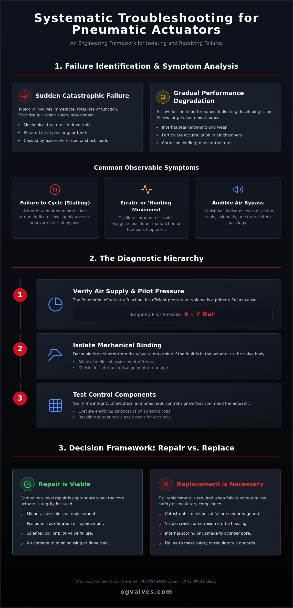
- Implement a hierarchical diagnostic approach for troubleshooting pneumatic actuator problems by first verifying system pilot pressure against the standard 6-7 Bar requirement.
- Isolate mechanical binding by decoupling the actuator from the valve body, allowing for a clinical assessment of the torque requirements and interface integrity.
- Execute electrical diagnostic protocols for solenoid coils and recalibrate pneumatic positioners to ensure control signal accuracy and response.
- Apply specific engineering criteria to determine when a component repair is viable versus when a full actuator replacement is necessary to maintain regulatory adherence.
Identifying Common Symptoms of Industrial Pneumatic Actuator Failure
Effective troubleshooting pneumatic actuator problems begins with a clinical categorization of observed symptoms. A Pneumatic actuator is designed for high-cycle reliability, but performance deviations often manifest as early warning signs of systemic failure. Identifying these indicators before a total loss of control is essential for maintaining plant safety and operational output in heavy industrial applications.
Common failure symptoms include:
- Failure to Cycle (Stalling): This occurs when the actuator cannot overcome the breakaway torque of the valve under full process pressure. It often indicates a critical drop in supply pressure or significant internal seal bypass.
- Erratic or ‘Hunting’ Movement: In modulating control applications, an actuator that oscillates around a setpoint suggests a feedback loop error or a malfunctioning positioner.
- Audible Air Bypass: High-velocity air sounds indicate leakage. Internal bypass occurs across the piston or vane seals, while external leaks are found at the solenoid interfaces or stem packings.
Sudden vs. Gradual Malfunction: Diagnostic Implications
Distinguishing the timeline of failure is a primary diagnostic requirement. Sudden catastrophic failures typically involve mechanical fractures within the drive train. In 2026, scotch yoke and rack and pinion designs remain susceptible to sheared drive pins or gear tooth failure if they’re subjected to excessive torque loads. Gradual performance degradation, however, is usually a symptom of seal hardening or the accumulation of particulate matter in the air chambers. Environmental factors, such as the corrosive atmospheres found in chemical processing, can compromise the actuator housing, leading to structural micro-fractures that worsen over time.
Visual and Auditory Inspection Protocols
A structured inspection protocol is necessary to isolate the fault source. Technicians must check for external stem leaks and visible housing cracks that signal material fatigue. Identifying “whistling” sounds is critical for locating bypass in the solenoid or piston seals. Corrosion on mounting brackets and drive couplings often leads to misalignment, which is a frequent issue in high-performance butterfly valves. Maintaining precise alignment ensures that torque is transferred efficiently, preventing premature wear on both the actuator and the industrial valves they control.
The Diagnostic Hierarchy: Air Supply and Pilot Pressure Evaluation
The integrity of the compressed air supply serves as the foundational layer when troubleshooting pneumatic actuator problems. Mechanical components can’t function without a stable, high-volume energy source. Industrial actuators typically operate within a pilot pressure range of 6 to 7 Bar. However, a static gauge reading at the compressor rarely reflects the dynamic pressure at the actuator inlet during an active cycle. If the pressure drops significantly when the valve is commanded to move, the actuator may stall or fail to achieve its full torque rating.
Peak plant demand often causes transient pressure drops that are invisible during off-peak testing. When multiple pneumatic systems cycle simultaneously, the local accumulator or header might be insufficient to maintain the required 6 Bar. This leads to erratic operation or failure to reach the end-of-stroke position. Technical teams must evaluate the volumetric flow rate, measured in Standard Cubic Feet per Minute (SCFM), to ensure the actuator receives enough air to fill the cylinder volume within the required stroke time.
Step-by-Step Pressure Integrity Testing
Start by isolating the actuator from the main air header to prevent back-pressure interference. Use calibrated gauges installed directly at the actuator inlet to verify both static and dynamic pressures. A common bottleneck exists in the pneumatic tubing or undersized fittings, which restricts the air volume required for large-bore valve operation. For a comprehensive protocol on field inspections, technical teams should consult a detailed actuator maintenance and troubleshooting resource to establish baseline performance metrics.
Air Quality and Contamination Management
Contamination is a frequently overlooked root cause of gradual actuator failure. Water vapor, oil carryover, and particulate matter create an abrasive slurry that destroys internal seals and clogs pilot orifices. In 2026, the demand for precision in automation requires strict adherence to ISO 8573-1 air quality standards. When troubleshooting pneumatic actuator problems, technicians must evaluate the condition of existing filter-regulator-lubricator (FRL) units.
Internal friction is the primary enemy of pneumatic efficiency. Without proper lubrication, the dynamic seals between the piston and the cylinder wall experience stick-slip motion. This results in jerky valve travel and increased wear on the O-rings. If troubleshooting confirms that the actuator’s internal bore is scored beyond repair, sourcing replacement industrial valves with pre-mounted, tested actuators ensures immediate restoration of plant safety.
Resolving Mechanical Binding and Valve-Actuator Interface Issues
When troubleshooting pneumatic actuator problems, technicians must distinguish between a failure of the pneumatic logic and a mechanical obstruction at the valve interface. Even with a verified 6 Bar air supply, an actuator will stall if the required breakaway torque exceeds its rated output. This often occurs when the valve’s internal friction increases due to process media buildup or seal degradation. It’s essential to analyze the mechanical linkage as a distinct failure point to prevent misdiagnosing a healthy actuator as faulty.
High-performance butterfly valves and gate valves present unique challenges in high-differential pressure systems. Fluid dynamic torque can shift significantly during the stroke, potentially exceeding the actuator’s torque curve. Additionally, over-tightened packing glands are a frequent cause of performance lag. Excessive compression on the stem packing increases friction. This directly impacts cycle times and can lead to premature wear of the actuator’s drive components.
Decoupling and Bench Testing Procedures
To isolate the fault, you must decouple the actuator from the valve body. This procedure requires strict adherence to safety protocols, ensuring the process line is depressurized before removing mounting bolts. Once removed, perform a “no-load” bench test by cycling the actuator at its rated pressure. If the actuator cycles smoothly, the internal rack and pinion or scotch yoke mechanism is likely intact. You should then manually cycle the valve stem using a lever or wrench to check for seat obstructions or stem seizing. If the valve doesn’t move freely, the issue is mechanical binding within the valve body rather than an actuator failure.
Alignment and Coupling Integrity
Precision in the valve-actuator interface is critical for long-term reliability. Misaligned mounting brackets cause “side-loading,” which exerts lateral force on the actuator shaft and leads to rapid seal failure. During your inspection, examine the drive nut and stem adapter for signs of rounding or wear. A compromised coupling cannot transfer torque efficiently, leading to lost motion or a complete failure to cycle. It’s a technical requirement to ensure the interface is properly lubricated and that the mounting hardware meets ISO 5211 standards for dimensional accuracy. If the drive nut shows significant deformation, it’s often more cost-effective to source high-specification replacement components than to attempt a field repair that may fail under load.
Troubleshooting Control Components: Solenoids and Positioners
Control components serve as the critical interface between the plant control system and the mechanical movement of the valve. When troubleshooting pneumatic actuator problems, identifying failures in these pilot devices is essential, as they are often the most sensitive parts of the assembly. These components utilize precision spool mechanisms and electronic coils that require strict adherence to technical specifications and environmental protection standards to maintain operational reliability.
Contamination within the pilot air supply is a leading cause of intermittent control failure. While the main actuator cylinder can sometimes tolerate minor particulate matter, the small orifices in pilot solenoids and positioners cannot. “Dirty” air containing moisture or oil carryover leads to stiction in the spool valves, preventing the actuator from exhausting or pressurizing correctly. Technicians should verify the functionality of manual overrides on pilot solenoids to determine if the fault is electrical or a result of a seized internal spool.
Solenoid and Coil Electrical Verification
Electrical diagnostics must begin with a multimeter assessment of the solenoid coil. Technicians should test for “open circuit” or “short circuit” conditions by measuring resistance across the coil terminals. It’s vital to verify that the supply voltage precisely matches the coil’s rated technical specifications, typically 24VDC or 110VAC in heavy industrial sectors. In 2026, many failures are traced to environmental moisture ingress in electrical enclosures that lack proper IP ratings or ATEX certification. If the enclosure shows signs of corrosion or condensation, the electrical integrity is likely compromised, necessitating a component replacement to meet safety benchmarks like SIL 2 or SIL 3.
Positioner Calibration and Feedback Issues
Pneumatic and electro-pneumatic positioners require precise calibration to ensure the valve reaches its intended state. Troubleshooting often involves resetting the zero and span settings to correct for signal drift. Mechanical feedback linkages are also prone to wear or slippage, which causes the positioner to “hunt” or overshoot the setpoint. Technicians must also inspect for positioner exhaust blockage, which creates back-pressure and significant lag in actuator response times. Modern digital positioners utilizing HART or Foundation Fieldbus protocols provide advanced diagnostics that can isolate these issues before they cause a total process shutdown.
If your diagnostic process reveals that control components are no longer holding calibration or have suffered catastrophic electrical failure, procure high-specification industrial valves with factory-integrated automation to restore your system to global engineering standards.
Strategic Component Replacement and Technical Procurement
The final phase of troubleshooting pneumatic actuator problems involves a critical assessment of the component’s remaining service life. Industrial operators must establish clear thresholds for when a field repair is no longer technically or economically viable. If an actuator has suffered internal bore scoring or structural fatigue in the scotch yoke mechanism, the probability of recurring failure remains high. In these instances, a full replacement is the only protocol that ensures long-term process safety and adherence to regulatory standards like ISO 12490.
Sourcing high-specification industrial valves and automation is necessary to ensure compatibility with existing control logic. When a legacy actuator fails, it’s an opportunity to upgrade to units with superior material classifications that better resist the specific environmental stressors of the facility. Leveraging technical support for the fast-track delivery of these mission-critical components is essential for minimizing unplanned downtime in heavy industrial sectors.
Failure Mode and Effects Analysis (FMEA) for Actuators
Implementing a Failure Mode and Effects Analysis (FMEA) allows technical teams to document patterns discovered while troubleshooting pneumatic actuator problems. This systematic approach identifies whether a failure is an isolated mechanical event or a symptom of systemic plant issues, such as poor air quality or excessive vibration. Technicians should evaluate the cost of repair against the reliability of a new unit, considering that a refurbished actuator may not carry the same performance guarantees as an API-certified replacement. Selecting the correct material specifications, such as nickel-plated internals or stainless steel housings, is a technical requirement for corrosive environments to extend the Mean Time Between Failures (MTBF).
Securing High-Quality Industrial Spares
The integrity of a flow control system depends on the quality of its individual components. Utilizing global supply chains for specialized ball valves and actuators ensures that all replacement parts meet rigorous API and ISO certification standards. High-grade equivalent or OEM components are essential for maintaining the safety ratings of the entire valve assembly. A proactive preventative maintenance schedule, based on the diagnostic data collected during troubleshooting, should include regular seal replacements and pilot valve inspections. This methodical approach to technical procurement transforms reactive maintenance into a strategy of unwavering operational reliability.
Optimizing Operational Reliability through Systematic Diagnostics
Maintaining peak industrial output in 2026 requires a clinical adherence to diagnostic protocols. By prioritizing air supply integrity and isolating mechanical binding from control logic failures, technicians can effectively minimize unplanned downtime and ensure fail-safe reliability. Troubleshooting pneumatic actuator problems isn’t merely about restoring movement; it’s about validating that every component meets rigorous engineering benchmarks like ISO 12490. When a systematic audit reveals that an actuator can’t maintain calibration or has suffered structural fatigue, a proactive replacement strategy is the only way to safeguard your process integrity. Reliability isn’t optional.
OG VALVES LTD. serves as a dependable partner for critical infrastructure. We offer an extensive ISO and API certified inventory designed for the most demanding environments. Our team provides expert technical support for heavy industry procurement alongside global fast-track delivery to mitigate the risks of catastrophic failure. Accurate diagnostics today prevent the operational failures of tomorrow, and we’re ready to support your next high-stakes project with the precision your facility demands.
Request a Technical Quote for Industrial Actuators and Valves
Frequently Asked Questions
What are the first steps to take when a pneumatic actuator fails to open?
Verify the air supply and control signal first. Check the local pressure gauge to ensure the pilot pressure meets the 6 Bar minimum requirement. Confirm that the solenoid valve is receiving the correct voltage and that the manual override functions. If the pneumatic and electrical inputs are verified, the issue likely resides in mechanical binding within the valve body or a failed internal actuator seal. This initial triage is essential for isolating the fault source.
How do I determine if a leak is internal or external on a pneumatic actuator?
External leaks are identified by audible whistling or visible bubbles when applying a leak detection solution to joints, stem seals, or exhaust ports. Internal leaks occur across the piston or vane seals and are diagnosed by checking the exhaust port of the control valve while the actuator is under pressure. If air continuously exhausts when the actuator is at the end of its stroke, the internal seals have failed and require immediate technical attention.
Can a pneumatic actuator be repaired while the valve is in-line?
Minor repairs such as solenoid replacement or positioner recalibration can be performed while the valve is in-line, provided the process is isolated. However, replacing internal seals or drive components usually requires removing the actuator from the valve body. OG VALVES LTD. is a specialist supplier that provides high-specification components but doesn’t offer on-site installation services. Facility teams must perform these mechanical interventions according to established site safety protocols to maintain operational integrity.
What air pressure is required for a standard double-acting pneumatic actuator?
Standard industrial double-acting actuators typically require a minimum operating pressure of 6 Bar to achieve their rated torque output. Operating below this threshold leads to stalling or failure to overcome the valve’s breakaway torque under full process pressure. When troubleshooting pneumatic actuator problems, technicians must verify that the dynamic pressure remains stable throughout the entire stroke. This ensures that the actuator provides sufficient force to maintain the integrity of the automation and flow control system.
Why is my pneumatic actuator moving slowly or ‘drifting’ during the cycle?
Slow movement often indicates insufficient air volume, restricted exhaust ports, or excessive friction in the valve packing gland. Drifting occurs when internal seals bypass or when the control valve doesn’t hold pressure in the cylinder. This is common in modulating applications where a faulty positioner fails to maintain a steady feedback signal. Check for clogged silencers or undersized pneumatic tubing that might be throttling the air flow and causing significant performance lag.
How often should industrial pneumatic actuators undergo preventative maintenance?
Industrial pneumatic actuators should undergo a formal inspection every six to twelve months, depending on cycle frequency and environmental severity. High-cycle applications or those in corrosive atmospheres require more frequent seal checks and lubrication. Implementing a preventative maintenance schedule based on ISO 12490 standards helps mitigate the risk of unplanned downtime. Consistent monitoring of air quality according to ISO 8573-1 also extends the service life of sensitive pilot components and prevents premature failure.
What is the difference between a double-acting and a spring-return failure mode?
A double-acting actuator requires air pressure to move in both directions and will remain in its last position upon loss of air supply. A spring-return actuator uses mechanical springs to drive the valve to a predetermined fail-safe state, such as fail-closed or fail-open, when air pressure is lost. This fail-safe capability is a critical safety requirement for hazardous processes where a specific valve state must be guaranteed during an emergency or power loss.
How do I test a solenoid valve coil for failure?
Test a solenoid valve coil by measuring its electrical resistance with a multimeter to identify open or short circuits. A healthy coil should show a specific resistance value according to its technical data sheet. If the multimeter indicates infinite resistance, the coil is open and must be replaced. You should also verify that the supply voltage at the terminals matches the coil’s rated specification, typically 24VDC or 110VAC, to ensure proper magnetic actuation.
 Responsive Menu