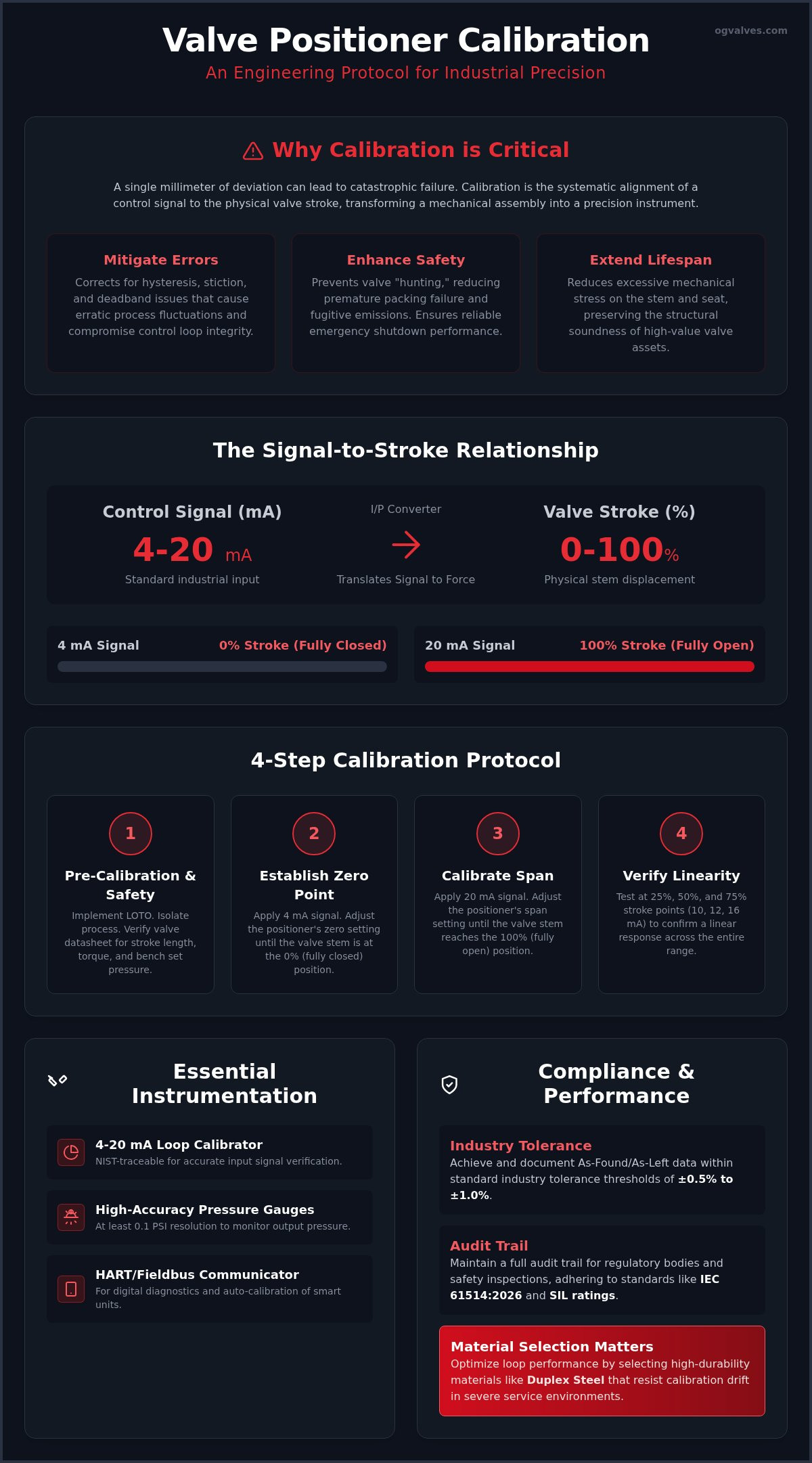
A single millimeter of deviation in a valve stroke can precipitate catastrophic failure in high-pressure petrochemical systems. Engineering professionals recognize that even high-specification components like globe or butterfly valves are only as effective as the accuracy of their actuation. Operational downtime resulting from valve hunting or deadband issues often stems from a failure to implement a rigorous valve positioner calibration procedure. You’ve likely encountered the challenges of premature stem wear or regulatory non-compliance when signal-to-stroke alignment drifts beyond permissible tolerances.
This technical guide provides a clinical protocol for calibrating both pneumatic and smart valve positioners to ensure industrial precision. It adheres to the IEC 61514:2026 standard for evaluating static and dynamic performance in industrial-process control systems. We’ll examine the mechanical checks required for feedback linkages, the precise adjustment of zero and span settings within 3-15 PSI or 6-30 PSI ranges, and the execution of digital auto-calibration for advanced smart units. Mastering these procedures ensures a full audit trail for regulatory bodies and extends the functional lifecycle of critical infrastructure.
Key Takeaways
- Define the systematic alignment of 4-20 mA control signals to physical stem displacement to mitigate hysteresis and deadband errors.
- Execute a precise valve positioner calibration procedure using clinical instrumentation such as loop calibrators and high-accuracy pressure gauges.
- Follow a rigorous step-by-step protocol to establish the zero point and calibrate the feedback span for 100% stroke alignment.
- Maintain regulatory compliance by documenting As-Found and As-Left data against standard industry tolerance thresholds of ±0.5% to ±1.0%.
- Optimize control loop performance through the selection of high-durability materials like Duplex Steel that resist calibration drift in severe service environments.
The Technical Necessity of Valve Positioner Calibration
Calibration is the systematic alignment of a control signal, typically 4-20 mA, to the physical stroke of the valve stem. This procedure transforms a standard mechanical assembly into a precision instrument capable of maintaining process stability at safety-critical thresholds. A rigorous valve positioner calibration procedure is the only reliable method to mitigate the cumulative effects of hysteresis and mechanical stiction. Without this alignment, deadband issues emerge, which compromise control loop integrity and lead to erratic process fluctuations. It’s essential to understand that software cannot compensate for underlying mechanical misalignment.
For high-specification industrial valve actuators deployed in heavy industry, precision is a requirement for operational survival. Misalignment leads to excessive mechanical stress on the stem and increased energy consumption as the actuator fights against internal resistance. Adherence to global benchmarks, such as API 600 or ISO standards, requires documented evidence of periodic calibration. This practice ensures that the valve seat and stem experience minimal wear, preserving the structural soundness of high-value assets like globe and butterfly valves over long service intervals.
Signal-to-Stroke Relationship Explained
The relationship between the control signal and the percentage of valve opening is designed to be linear in most control applications. In a standard setup, a 4 mA signal represents a 0% stroke, while 20 mA corresponds to a 100% open state. Identifying non-linearities is critical when differentiating between rotary and linear valve applications. While globe valves typically exhibit a direct linear response, rotary ball or butterfly valves may require characterized cams or software adjustments to maintain signal integrity across the full travel range. The I/P converter acts as the primary translator in this system, converting electronic commands into the pneumatic force required to manipulate control valve components with clinical accuracy. This conversion must be verified during the valve positioner calibration procedure to account for air supply fluctuations or diaphragm wear.
Regulatory and Safety Implications
In petrochemical and heavy industrial sectors, adherence to Safety Integrity Level (SIL) ratings is a mandatory operational constraint. An uncalibrated positioner can cause the valve to “hunt,” where the component oscillates around a setpoint. This behavior causes premature packing failure and significantly increases the risk of fugitive emissions. Precise seating of globe and butterfly valves remains the primary defense against leaks that violate environmental standards. Regular, documented calibration provides the necessary audit trail for safety inspections. It’s the protocol that ensures the system responds correctly during emergency shutdown events, where a failure to reach the zero-percent stroke position could result in catastrophic pressure surges or containment loss.
Pre-Calibration Requirements and Essential Instrumentation
Safety protocols represent the primary phase of any valve positioner calibration procedure. Technicians must implement Lock-out/Tag-out (LOTO) and verify process isolation before attempting any mechanical or pneumatic adjustments. A clinical approach to documentation is equally vital. Engineers should consult the specific valve datasheet to confirm the required stroke length, torque specifications, and the bench set pressure. Verifying the bench set ensures the actuator spring is correctly tensioned to achieve the desired fail-safe position before the positioner is even mounted. Failure to verify these parameters often leads to signal-to-stroke misalignment that cannot be corrected through the positioner alone.
The instrumentation used must meet rigorous industrial standards. High-accuracy pressure gauges with a resolution of at least 0.1 PSI are necessary to monitor output pressure during the calibration cycle. Technicians don’t often realize that signal drift in cheap calibrators can invalidate an entire day’s work. The following tools are mandatory for a professional valve positioner calibration procedure:
- NIST-traceable 4-20 mA loop calibrator for input verification
- Pneumatic regulator capable of holding a stable 20-30 PSI supply
- HART or Fieldbus communicator for digital diagnostics
- Precision calipers for stroke measurement verification
Instrumentation and Tool Specification
Precise signal generation is the baseline for accuracy. Using a high-precision loop calibrator allows for discrete steps (4, 8, 12, 16, 20 mA) to verify linearity across the full range of travel. Pneumatic regulators must provide a stable 20-30 PSI supply, as fluctuations in supply pressure can introduce erratic behavior in the pilot valve or relay. For smart positioners, a HART communicator is essential for accessing diagnostic data and configuring internal parameters. This level of detail aligns with the standards found in this Control Valve Commissioning Guide, which emphasizes the necessity of verified instrumentation during the initial setup phases.
Environmental and Mechanical Checks
Before applying power or air, a physical inspection is mandatory. The mechanical feedback linkage must be checked for play or misalignment. Even minor looseness introduces hysteresis that software calibration cannot resolve. Technicians must verify the integrity of pneumatic tubing and fittings to prevent leaks that degrade signal response. Ensure the valve stem is free from debris and that the packing is not overtightened, as excessive friction causes mechanical stiction. For critical infrastructure, utilizing high-specification globe or ball valves ensures that mechanical tolerances remain within design benchmarks during these rigorous checks. This pre-calibration phase is the foundation of long-term operational reliability.
Step-by-Step Calibration Procedures for Industrial Positioners
Executing a valve positioner calibration procedure requires a methodical three-phase approach to ensure signal-to-stroke integrity. Phase 1 focuses on establishing the zero point. This involves aligning the 4 mA input signal with the fully closed valve position, ensuring the seat load is sufficient to prevent leakage. Phase 2 involves setting the span. During this phase, the technician adjusts the feedback mechanism so that a 20 mA signal corresponds exactly to a 100% stroke. Finally, Phase 3 requires linearity checks. This stage verifies accuracy at 25%, 50%, and 75% signal intervals to confirm the valve responds predictably across its entire operating range.
Technicians must distinguish between bench-set calibration and in-situ calibration. Bench-set procedures occur in a controlled workshop environment to verify the actuator’s spring range and initial positioner alignment. In-situ calibration is performed after the valve is installed in the process line. This second stage is critical because it accounts for real-world variables like process differential pressure and packing friction. These forces often differ from workshop conditions and can significantly impact the final stroke accuracy of high-specification ball valves or needle valves.
Pneumatic Positioner Calibration (Manual)
Manual calibration of pneumatic units remains a standard requirement for many legacy systems. The process begins by adjusting the zero screw until the valve stem just begins to move at 4.1 mA, then backing off until it’s firmly seated at 4.0 mA. Following this, the technician modifies the span lever or range spring to achieve full travel at 20 mA. It’s an iterative process. Adjusting the span often shifts the zero point, requiring the technician to toggle between the two endpoints multiple times until the calibration stabilizes within the allowed tolerance, typically ±0.5% of the total span.
Smart Positioner Calibration (Digital)
Smart positioners utilize microprocessor logic to simplify the alignment process. Technicians initiate the ‘Auto-Travel’ routine via the local push-button interface or a HART communicator. The device automatically identifies the physical end-stops and calculates optimal gain settings to minimize overshoot. Manual overrides are still necessary for specialized globe valves or butterfly valves used in severe service. In these cases, engineers may configure split-range setups or custom characterization curves to compensate for non-linear process dynamics or to coordinate the operation of multiple valves within a single control loop.
Linearity Verification and Adherence to Regulatory Standards
The final phase of a valve positioner calibration procedure centers on verifying that the assembly meets defined industrial tolerance levels. For most high-precision control loops, the acceptable deviation is restricted to a range of ±0.5% to ±1.0% of the total span. If the valve fails to reach these benchmarks, it indicates a fundamental mechanical or pneumatic deficiency. Technicians must document the ‘As-Found’ data to establish a baseline of the valve’s performance before any adjustments. This is followed by the ‘As-Left’ data, which serves as the official record of the component’s state upon its return to service. This documentation is a mandatory requirement for aligning operations with ISO 9001 quality management systems and API 598 testing standards.
Rigorous testing ensures that the valve doesn’t just reach its endpoints, but operates reliably across the entire signal range. Procurement specialists should prioritize API 598 compliant valves to ensure the hardware is capable of maintaining these tight tolerances under high-pressure conditions.
Hysteresis and Repeatability Testing
Hysteresis tests identify mechanical wear within the actuator or valve stem by measuring the difference in position when approaching a setpoint from opposite directions. A technician records the stem position at 50% signal while increasing the input, then repeats the measurement while decreasing the input. Any discrepancy suggests friction issues within the packing glands of industrial valves. High friction leads to an expanded deadband. Deadband represents the specific range of signal change that results in no physical movement. If the deadband exceeds the manufacturer’s specification, the valve will likely ‘hunt’ or oscillate, causing premature failure of the seating surfaces.
Final Documentation and Reporting
Every completed calibration must culminate in a formal calibration certificate. This document serves as the primary audit trail for insurance and regulatory inspections. It must include the component serial number, the specific test equipment utilized, and a formal technician sign-off. Scheduling these intervals isn’t a generic task. Frequency should be determined by the valve’s duty cycle and the criticality of the process loop. Safety-critical systems often require quarterly verification, while standard utility lines may only need annual checks. Maintaining these records ensures full compliance during environmental and safety audits, providing proof that the infrastructure meets global engineering benchmarks.
High-specification hardware from OG VALVES LTD. acts as the critical foundation for any valve positioner calibration procedure. While a positioner manages the signal-to-stroke relationship, the mechanical integrity of the valve body and stem determines the long-term stability of that alignment. Low-grade components often suffer from structural flex or premature wear, which introduces unpredictable variables that software cannot resolve. By utilizing precision-engineered components, technical experts ensure that the calibrated setpoints remain accurate throughout the service interval, even under extreme process conditions. This technical synergy between actuation and valve mechanics is essential for achieving the zero-error performance required in heavy industrial sectors.
The relationship between material selection and calibration stability is quantifiable. Components that lack the necessary structural soundness will drift over time, necessitating frequent and costly recalibration cycles. Utilizing high-value assets like globe, butterfly, or ball valves ensures that the physical travel limits remain fixed, allowing the positioner to maintain its span without mechanical interference. This reliability is the benchmark for operational excellence in safety-critical systems.
Material Integrity and Calibration Stability
Thermal expansion represents a significant challenge in high-temperature environments. Standard carbon steels may expand at rates that shift the physical end-stops of a valve, effectively invalidating a previous valve positioner calibration procedure. Selecting materials like Duplex Steel provides superior dimensional stability and corrosion resistance, ensuring the valve stroke remains consistent across wide temperature gradients. Engineers must also select actuators and positioners that precisely match the torque requirements of large-bore gate valves. Under-specified actuation leads to sluggish response times and increased hysteresis. Ensuring compatibility between the control signal and the specific environmental conditions, such as corrosive offshore atmospheres, is vital for maintaining the structural soundness of the entire assembly.
Global Supply and Technical Expertise
OG VALVES LTD. maintains an extensive inventory of high-specification industrial components to support immediate project requirements. This stock availability is essential for preventing extended plant outages during scheduled maintenance or emergency repairs. Fast-track delivery of technical components like plug valves and needle valves allows operators in the Oil, Gas, and Power sectors to restore process integrity without the delays associated with standard supply chains. Leveraging technical support during the procurement phase ensures that the specified hardware is fully compatible with the intended control loop logic. OG VALVES LTD. is a specialist in industrial valve procurement for heavy industry, providing the technical precision and durability required for global infrastructure projects.
Advancing Industrial Precision through Standardized Protocols
Precision calibration is the final stage of industrial valve specification, transforming a mechanical component into a high-accuracy control instrument. Implementing a rigorous valve positioner calibration procedure mitigates hysteresis and deadband errors that otherwise compromise process stability in safety-critical environments. This clinical approach to alignment ensures that 4-20 mA control signals translate into exact physical displacement, preserving the integrity of valve seats and stems across extended duty cycles.
The success of these technical protocols depends on the structural soundness of the underlying hardware. OG VALVES LTD. provides the engineering excellence required for large-scale projects, offering an extensive inventory of gate, ball, and butterfly valves designed to meet API and ISO standards. Our deep technical expertise in the petrochemical and power sectors ensures that every component is specified for durability and regulatory adherence. With global fast-track delivery, we support critical infrastructure by minimizing downtime and securing long-term operational output. It’s clear that precision in the field starts with the right specification.
Request a Technical Quote for Industrial Valves and Actuators to secure high-specification components for your next project. Professional adherence to these engineering benchmarks ensures unwavering reliability in the most demanding industrial applications.
Frequently Asked Questions
What is the difference between a valve positioner and an I/P converter?
An I/P converter is a basic transducer that converts a 4-20 mA signal into a proportional pneumatic output, typically 3-15 PSI. It lacks a feedback mechanism. In contrast, a valve positioner is a sophisticated controller that monitors the physical stem position. It continuously adjusts the pneumatic pressure to the actuator until the valve reaches the precise setpoint. This feedback loop is what differentiates the two components in high-pressure industrial systems.
How often should an industrial valve positioner be calibrated?
Calibration frequency depends on the criticality of the process loop and the environmental duty cycle. Safety-critical systems, such as those in petrochemical plants, often require quarterly or bi-annual verification. Standard utility lines might only need an annual valve positioner calibration procedure. Harsh environments with high vibration or extreme thermal fluctuations necessitate more frequent checks to prevent signal drift and maintain the structural soundness of the valve assembly.
Can I calibrate a smart positioner without a HART communicator?
Most modern smart positioners feature a local push-button interface and an LCD for basic configuration and auto-travel routines. You don’t strictly require a HART communicator for standard setup. However, a communicator is essential for accessing deep diagnostics, historical data, and secondary parameters. It’s also necessary for configuring custom characterization curves in complex control loops where a simple linear response isn’t sufficient for process stability.
What causes a valve positioner to lose its calibration over time?
Calibration drift results from several mechanical and pneumatic factors. Constant vibration in heavy industrial environments can loosen feedback linkages or mounting brackets. Thermal expansion in high-temperature applications shifts the physical end-stops of the valve stem. Contamination in the instrument air supply often degrades the internal pilot valve or relay. These variables, combined with increased packing friction, gradually alter the signal-to-stroke relationship established during the initial valve positioner calibration procedure.
What is ‘split-ranging’ in valve positioner calibration?
Split-ranging is a control strategy where two or more valves operate from a single 4-20 mA signal. For example, a small valve might stroke from 0% to 100% using 4-12 mA, while a larger valve strokes from 12-20 mA. This requires precise calibration of each positioner’s zero and span settings. It’s a common technique in heating and cooling systems to provide fine control at low flow rates while maintaining high capacity.
How do I identify if the actuator or the positioner is causing a calibration error?
Technicians should perform a manual override test to isolate the failure point. By applying a regulated air supply directly to the actuator and bypassing the positioner, you can observe the mechanical response. If the valve strokes smoothly and reaches its bench set limits, the actuator is functional. If the assembly exhibits jerky movement or fails to stroke, the issue lies with the actuator springs, diaphragm, or internal valve friction rather than the positioner.
Is it necessary to remove the valve from the line for calibration?
Removal from the process line isn’t required for standard calibration. In-situ calibration is actually preferred because it accounts for real-world variables like packing friction and process differential pressure. However, the valve must be isolated using a bypass loop or the process must be offline. Attempting a calibration on a live process is dangerous. It can cause downstream pressure surges or trigger emergency shutdown systems if the valve strokes unexpectedly.
What are the common signs that a valve positioner requires immediate recalibration?
Immediate recalibration is necessary if the valve begins to “hunt” or oscillate around a setpoint. This behavior indicates that the positioner is struggling to find the correct signal-to-stroke alignment. Other signs include a significant deadband, where the signal changes but the stem doesn’t move, or an overshoot where the valve travels past the desired position. Failure to reach the fully closed or fully open limits at 4 mA or 20 mA is also a critical indicator.
 Responsive Menu