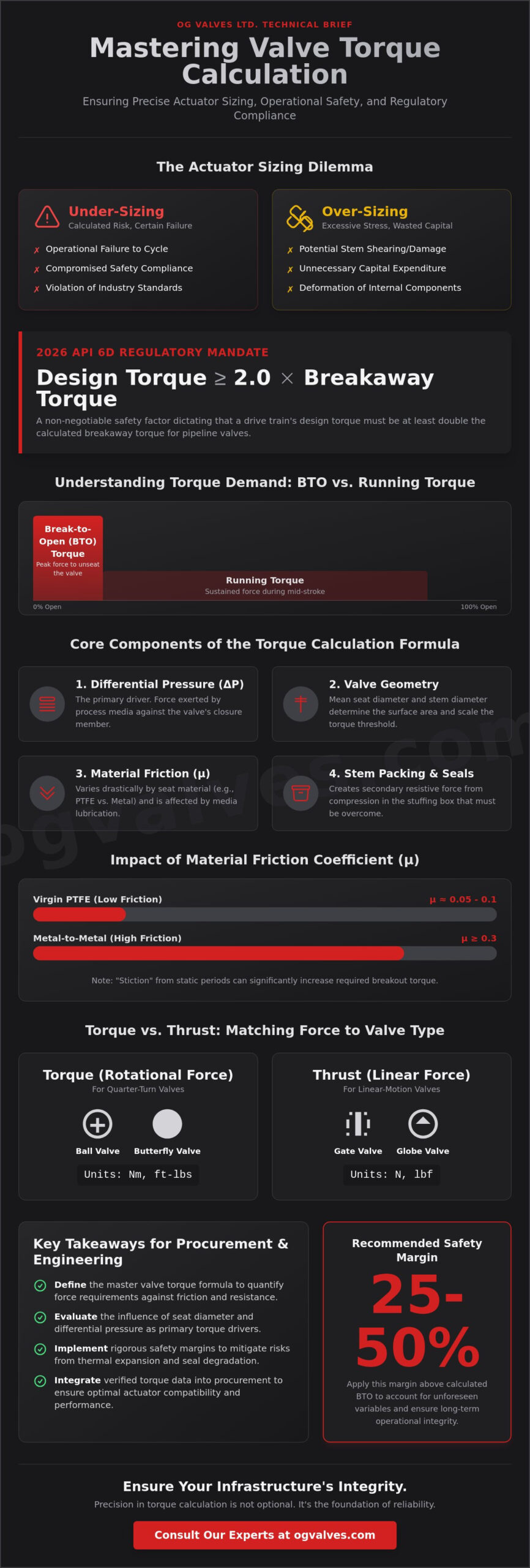
The 2026 regulatory landscape dictates that a drive train’s design torque must be at least 2.0 times the calculated breakaway torque for pipeline valves under API 6D. Anything less is a calculated risk your infrastructure cannot afford. You’ve seen how relying on a generic valve torque calculation formula often results in actuator under-sizing, which leads to operational failure, or over-sizing, which causes unnecessary expenditure and potential stem damage. Precise calculation isn’t just about the math. It’s about accounting for dynamic friction, material stiffness, and the latest international safety benchmarks.
You understand that precise torque figures are the foundation of actuator sizing and operational longevity. This guide provides a rigorous technical breakdown of the methodologies required to ensure precise actuator sizing and total operational safety across your gate, ball, and butterfly valve inventory. We’ll examine the impact of the 2025 ASME BPVC updates, the specific variables for high-pressure systems, and the application of safety factors to guarantee long-term operational integrity. This clinical focus on engineering excellence ensures your procurement and technical teams can maintain compliance with global standards while optimizing valve performance.
Key Takeaways
- Define the master valve torque calculation formula to quantify rotational force requirements against internal resistance and friction coefficients.
- Evaluate the geometric influence of mean seat diameter and differential pressure as the primary drivers of torque demand in quarter-turn and linear systems.
- Implement rigorous safety margins between 25% and 50% to mitigate operational risks associated with thermal expansion and seal degradation.
- Integrate verified torque data into the procurement process to ensure optimal actuator compatibility and long-term performance for critical industrial valves.
Fundamentals of Valve Operating Torque and Actuation Requirements
Valve torque is defined as the rotational force required to overcome internal mechanical resistance and fluid pressure to cycle a valve. In high-stakes industrial environments, the precision of the valve torque calculation formula determines the reliability of the entire flow control system. Under-sizing an actuator results in a failure to cycle under full differential pressure. Conversely, over-sizing introduces excessive mechanical stress that can shear stems or deform internal components. Reliability in critical infrastructure depends on this technical equilibrium.
Engineering teams must distinguish between Break-to-Open (BTO) torque and running torque. BTO represents the maximum force needed to unstick the sealing elements from their seats after a period of stasis. Running torque is the lower, sustained force required during the mid-stroke transition. Failure to account for these variations can compromise safety compliance, especially under the 2026 API 6D specifications which mandate a 2.0 safety factor for drive train calculations. The valve torque calculation formula must account for these peak loads to ensure consistent performance across the valve’s service life.
The Mechanics of Torque Formation
Seat friction serves as the primary component of resistive force. In ball and butterfly valves, the interference fit between the closure member and the seat material dictates the base torque. Stem packing friction adds a secondary layer of resistance, often influenced by the tightness of the packing gland and the material properties of the seals. Fluid pressure differentials (ΔP) exert axial loads on the stem and closure member, significantly increasing the force required to initiate movement. These variables must be meticulously quantified to avoid operational downtime. Material choice, such as RTFE or metal-to-metal seating, further complicates the friction coefficient and must be factored into the engineering data.
Torque vs. Thrust in Industrial Valves
The methodology for force calculation differs based on valve geometry. Quarter-turn valves, including ball, butterfly, and plug valves, require torque measurements typically expressed in Newton-meters (Nm) or foot-pounds (ft-lbs). Linear valves, such as gate and globe valves, necessitate thrust calculations measured in Newtons (N) or pounds-force (lbf). When integrating automated systems, engineers must apply specific conversion factors to account for the mechanical advantage provided by gear operators. This ensures that the output from the actuation unit aligns with the mechanical limits of the valve stem and drive train. Accurate conversion is essential for maintaining the structural soundness of the valve assembly under peak load conditions.
Primary Variables in Valve Torque Calculation
Differential pressure (ΔP) is the primary driver in any valve torque calculation formula. It quantifies the force exerted by the process media against the closure member, directly scaling the required seating and unseating forces. Mean seat diameter provides the geometric basis for this calculation. As diameter increases, the surface area exposed to ΔP grows quadratically, which substantially elevates the torque threshold. Precise measurement of these dimensions is essential for engineering accuracy in high-pressure applications.
Stem diameter and packing depth introduce secondary but critical resistive forces. Compression within the stuffing box creates a friction load that the actuator must overcome before any movement occurs. Technical data, such as the NRC Design Basis Valve Stem Torque guidelines, highlights that stem factor and lubrication levels significantly alter these variables. Engineers must account for the specific material classifications of the packing, whether graphite or PTFE, to prevent actuator stall or stem deformation.
Material Friction Coefficients
The friction coefficient (μ) varies drastically between seat materials. Virgin PTFE offers a low μ, typically ranging from 0.05 to 0.1, while metal-to-metal seating in high-temperature ball valves can reach 0.3 or higher. Media lubrication plays a decisive role; dry gas service increases friction, whereas oily media acts as a lubricant. “Stiction” remains a critical concern for valves left in a static position for extended periods. This cold-flow or bonding effect requires a higher breakout torque than the nominal running torque. It’s a factor that must be integrated into the valve torque calculation formula during the initial design phase to ensure reliable unseating.
Hydraulic and Hydrodynamic Forces
In high-pressure service, the “piston effect” generates an axial load on the valve stem, forcing it against the thrust bearings. This increases the mechanical resistance within the drive train. For butterfly valves, hydrodynamic torque becomes a dominant factor as fluid velocity increases. The disc acts as an airfoil, creating a pressure differential that attempts to close or open the valve depending on its position. Engineers must calculate these dynamic forces to ensure the actuator maintains control throughout the full stroke. Selecting the correct industrial valves requires a complete analysis of these hydraulic variables against the intended flow conditions to prevent operational failure.

The application of a valve torque calculation formula requires a precise understanding of the mechanical interactions within different valve architectures. For most quarter-turn applications, the fundamental calculation follows the structure: T = (Fp + Fs) x r x μ. In this equation, Fp represents the force generated by differential pressure, Fs denotes the initial seat pre-compression force, r is the mean radius of the seat, and μ is the friction coefficient of the material interface. This base figure must then be adjusted for stem packing friction (T_packing) and bearing resistance to ensure the actuator provides sufficient breakout force under peak load conditions.
Ball Valve Torque Calculation
In ball valve design, the torque requirement is primarily a function of seat load. For floating ball designs, the ball is forced into the downstream seat by the process media. This means torque increases linearly with differential pressure. Conversely, trunnion ball valves utilize fixed stems and spring-loaded seats. This configuration distributes the pressure load to the bearings rather than the seat interface. It results in lower operating torque for large-diameter or high-pressure service. The calculation must sum the seat friction torque, stem seal friction, and bearing friction to reach a definitive total for procurement specifications.
Butterfly Valve Dynamic Torque
Butterfly valve torque is more complex due to the influence of fluid velocity. While seating torque is critical, hydrodynamic torque (Th) often dictates actuator sizing for throttling applications. This dynamic force is calculated as Th = Kt x D^3 x ΔP, where Kt is a coefficient determined by the disc’s angle of opening. The use of a triple offset butterfly valve significantly alters the valve torque calculation formula by utilizing a cam-like action. This geometry eliminates seat friction throughout the stroke. It only engages the seal at the final point of closure, which minimizes the breakout torque requirements compared to concentric or double-offset designs.
Gate Valve Stem Torque
Linear valves like gate and globe valves require a conversion from linear thrust to rotational torque at the stem nut. The required thrust is first calculated by accounting for the seat area, differential pressure, and stem diameter. Once total thrust (Ft) is determined, the required torque (T) is derived using the formula: T = (Ft x L) / (2 x π x e). Here, L represents the lead of the stem thread and e is the mechanical efficiency of the drive nut, typically ranging from 0.25 to 0.40 for ACME threads. Precision here is vital. Miscalculating the efficiency factor often leads to under-powered actuation in high-pressure gate valve applications.
Accounting for Safety Factors and Environmental Variables
A theoretical valve torque calculation formula provides the baseline required for operation, but industrial reality necessitates the application of an Actuator Safety Factor (ASF). Industry standards generally dictate a safety margin between 25% and 50%. For standard, non-critical liquid service where the media is clean and temperatures remain stable, a 25% margin is often sufficient. In high-stakes gas applications or safety-instrumented systems (SIS), a 50% margin is mandatory. This accounts for the compressibility of the media and the heightened risk of stiction after long periods of inactivity.
The discrepancy between unseating and reseating torque is a critical engineering consideration. Breakout torque is almost always the peak value, yet certain high-velocity flows can create dynamic forces that make reseating more difficult than the initial opening. The 2026 API 6D specifications now mandate that the design torque for all drive train calculations must be at least 2.0 times the calculated breakaway torque. This rigorous standard ensures that the mechanical integrity of the stem and coupling can withstand the maximum output of the actuator without deformation.
The Actuator Safety Factor (ASF)
Determining the appropriate ASF requires a clinical assessment of the application’s criticality. Engineers must calculate for the absolute worst-case scenario. This includes the maximum operating differential pressure (MOPD) and the minimum available supply pressure for pneumatic or hydraulic systems. When integrating data from industrial valve actuators, the torque output at the lowest supply pressure must still exceed the valve’s breakout torque after the safety factor is applied. This ensures the valve cycles even during a partial loss of plant air or power.
Service Condition Adjustments
Environmental extremes drastically alter the internal friction coefficients of the valve assembly. These variables must be factored into the final torque requirement:
- Cryogenic Service: Material contraction and seal hardening at temperatures below -150°C significantly increase the force required to move the closure member.
- High-Temperature Steam: Thermal expansion of the stem and seats can lead to increased interference and potential binding in the stuffing box.
- Slurry and Particulates: Media containing solids can increase friction by up to 100% over time as particulates lodge in seat cavities and seal interfaces.
- Corrosion and Scaling: Internal buildup in aging piping systems increases the mechanical resistance of the closure member, often requiring a higher ASF to maintain reliability.
Long-term cycling leads to seat wear and torque drift. If your initial valve torque calculation formula is too marginal, these factors will eventually compromise operational safety. For technical assistance in selecting the correct safety margins for your critical infrastructure, consult our engineering team and view our full range of industrial valves designed for extreme service conditions.
Integrating Torque Data into Valve Specification and Procurement
The transition from theoretical engineering to physical procurement requires a seamless transfer of technical data. Once the valve torque calculation formula has yielded specific figures, these values must serve as the baseline for selecting industrial valves. Procurement specialists shouldn’t rely solely on manufacturer-provided catalogs. Independent verification against process-specific differential pressure and temperature variables is a mandatory step in quality assurance. This clinical approach prevents the acquisition of under-specified components that fail under peak operational loads.
High-stakes procurement demands rigorous documentation. Standards such as API 6D and API 600 require detailed design thrust and torque calculations for all drive train components. This documentation provides the audit trail necessary for regulatory compliance and safety certifications. Final validation occurs during Factory Acceptance Testing (FAT). During FAT, the actual breakout torque is measured under simulated differential pressure to confirm it aligns with the initial valve torque calculation formula results. Discrepancies at this stage indicate potential machining tolerances or material friction issues that must be addressed before the valve reaches the field.
Engineering Data Sheets and Specification
A comprehensive Request for Quotation (RFQ) for automated systems must include the Maximum Allowable Stem Torque (MAST). For a gate valve, the stem’s yield strength must exceed the maximum output of the actuator, including any safety margins. If the MAST is lower than the actuator’s stall torque, mechanical failure’s inevitable in a blockage scenario. Project managers must ensure that the torque requirements align with global standards like ISO 5211 for actuator mounting and API 622 for low-emission packing. This alignment guarantees that the valve and actuator operate as a unified, reliable assembly.
Procurement and Quality Assurance
OG VALVES LTD. acts as a dependable partner by providing technically validated components that meet these exacting requirements. Our engineering team ensures that every valve assembly undergoes rigorous testing to verify torque compliance. For critical infrastructure projects, we offer fast-track delivery for pre-calculated assemblies that have already passed FAT protocols. Before final installation, use this checklist to verify torque compliance:
- Verify MAST against the actuator’s peak stall torque.
- Confirm friction coefficients match the specific media and temperature profile.
- Review FAT reports for breakout and running torque consistency.
- Ensure compliance with the 2.0 safety factor for drive train components as per 2026 API 6D standards.
Securing Infrastructure Integrity through Engineering Precision
Implementing a rigorous valve torque calculation formula is the foundational requirement for ensuring the long-term structural soundness of your flow control assets. Precision during the design phase eliminates the operational risks associated with actuator under-sizing and mechanical overstress. As regulatory standards like API 6D mandate stricter safety margins, maintaining adherence to these benchmarks is essential for operational safety in high-pressure and corrosive environments. Integrating these calculations into a clinical procurement process ensures that every component meets the specific demands of your critical infrastructure.
Our organization provides the technical expertise required to bridge the gap between theoretical data and field-ready hardware. We maintain an API and ISO certified supply chain and offer global fast-track delivery to support large-scale industrial demands. Consult with our technical experts for precise valve and actuator specifications to optimize your system performance. You can depend on our clinical focus on durability and regulatory excellence to safeguard your operations. Achieve total system integrity with components engineered for unwavering reliability.
Technical Engineering Frequently Asked Questions
What is the difference between break torque and running torque in valves?
Break torque, or Break-to-Open (BTO), is the maximum rotational force required to initiate movement of the closure member from its fully seated position after a period of stasis. Running torque is the significantly lower force needed to maintain movement throughout the mid-stroke transition once the initial seal is broken. Actuators must be sized based on the peak BTO value to ensure the valve cycles reliably under full differential pressure.
How does differential pressure affect the valve torque calculation formula?
Differential pressure (ΔP) acts as a direct multiplier for seat friction by increasing the axial load on the closure member and stem bearings. As ΔP rises, the force pressing the ball or disc against the downstream seat increases, which elevates the mechanical resistance within the valve torque calculation formula. This relationship is typically linear in floating ball valves but is mitigated by bearing support in trunnion mounted designs.
Why is a safety factor necessary when sizing a valve actuator?
A safety factor accounts for unforeseen variables such as seat wear, friction drift, and fluctuations in supply pressure that occur over the valve’s service life. It provides a power reserve to prevent actuator stall if the media becomes contaminated or if the valve remains static for extended periods. Without this margin, the assembly lacks the torque necessary to overcome “stiction” and other environmental resistances.
Can temperature changes significantly alter the required operating torque?
Temperature extremes change the mechanical interference and friction coefficients of the valve’s internal components. Cryogenic service hardens seal materials and increases resistance, while high temperatures cause thermal expansion of the stem and seats, which can lead to binding in the stuffing box. Both scenarios require specific adjustments to the base torque figures to maintain operational integrity in extreme environments.
What is MAST (Maximum Allowable Stem Torque) and why does it matter?
MAST is the technical limit at which the valve stem or drive train will undergo permanent plastic deformation or mechanical failure. It’s essential that the actuator’s maximum stall torque doesn’t exceed the MAST value to prevent catastrophic damage during a blockage. Engineers must verify that the stem material and diameter can withstand the full output of the selected actuation unit.
How do I calculate torque for a valve handling abrasive slurries?
Handling abrasive slurries requires applying a specific service factor, often 1.5 to 2.0, to the standard valve torque calculation formula to account for particulate accumulation. Solids lodge in seat cavities and increase the friction coefficient (μ) through mechanical interference and surface scoring. This adjustment ensures the actuator has sufficient force to clear debris and maintain a tight shut-off during cycling.
Does the type of seat material (PTFE vs. Metal) change the calculation formula?
The seat material dictates the friction coefficient (μ) variable used within the calculation. Virgin PTFE seats offer a low μ, typically around 0.1, whereas metal-to-metal seating requires a coefficient of 0.3 or higher due to increased surface resistance. This variation means a metal-seated valve will require substantially more torque than a soft-seated valve of the same size and pressure rating.
What is the standard safety margin for an automated valve assembly?
The standard safety margin is 25% for clean, lubricating liquid service and 50% for gas or safety-critical applications. However, the 2026 API 6D specifications mandate that the design torque for all drive train calculations must be at least 2.0 times the calculated breakaway torque. This rigorous safety factor ensures the mechanical assembly remains reliable under the most demanding industrial conditions.
 Responsive Menu