When to Use a Globe Valve Instead of a Gate Valve: A Technical Selection Guide
May 01, 2026
Home+When to Use a Globe Valve Instead of a Gate Valve: A Technical Selection Guide
Selecting a gate valve for its minimal pressure drop is a standard engineering decision, yet applying this logic to a throttling application often leads to catastrophic seat erosion within 500 hours of operation. You understand that incorrect valve selection is the primary driver of unscheduled maintenance and system inefficiency in high-pressure environments. Understanding exactly when to use a globe valve instead of a gate valve is critical for maintaining the mechanical integrity of your flow control systems. This guide establishes a rigorous technical framework to ensure your selection meets API 623 and ASME B16.34 standards.
You’ll master the engineering nuances required to optimize flow dynamics and eliminate the 25% increase in maintenance costs typically associated with misinterpreted valve specifications. We will examine the specific pressure drop profiles, seat designs, and disc configurations that define long-term performance in steam, oil, and gas applications. This analysis provides the technical data necessary to secure your infrastructure against premature failure and ensure compliance with global safety protocols. By prioritizing industrial precision over generic procurement habits, you ensure that every component in your system operates within its designed performance envelope.
Key Takeaways
Identify the fundamental mechanical distinctions between linear motion valves to ensure correct application in isolation versus regulation scenarios.
Analyze the relationship between internal valve geometry and fluid friction to accurately quantify and mitigate pressure drop across industrial systems.
Determine the precise technical criteria for when to use a globe valve instead of a gate valve to maintain throttling control without compromising component durability.
Apply international compliance standards, including API and ASME specifications, to ensure material integrity in high-temperature and high-pressure environments.
Optimize global infrastructure projects by integrating high-specification valve inventory designed for rigorous performance and rapid deployment.
Technical Definitions: Distinguishing Globe and Gate Valve Mechanisms
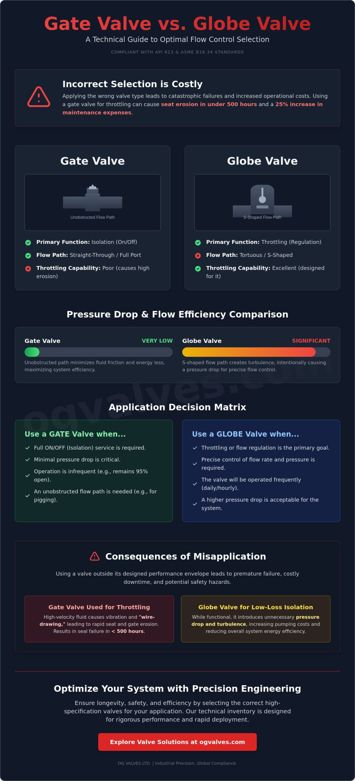
Linear motion valves serve as the engineering standard for high-pressure industrial systems. These components utilize a sliding-stem design to actuate the internal closure element along a straight axis. System integrity depends on the precise application of these designs. A gate valve functions strictly as an isolation component, intended for service in either a fully open or fully closed position. In contrast, a globe valve is engineered as a modulation and regulation component. Selecting the incorrect valve type for a specific application leads to rapid component degradation. Engineers must evaluate the fluid dynamics of each system to determine when to use a globe valve instead of a gate valve to prevent catastrophic seat erosion or cavitation.
Internal Architecture: Disc vs. Gate
The internal configuration of a gate valve relies on a wedge-shaped or parallel gate mechanism. This gate slides into the flow stream to provide a positive seal. Gate valve mechanisms are designed to provide an unobstructed flow path, which minimizes pressure drop across the valve body. However, this architecture is not suitable for throttling. If a gate valve is partially opened, the high-velocity fluid creates vibration and “wire-drawing” across the gate’s seating surfaces.
Globe valves utilize a movable disc and a stationary ring seat within a globular body. The flow path follows an S-shaped trajectory, which forces the fluid to change direction twice. The disc-to-seat relationship defines the flow regulation capability. Because the disc moves parallel to the flow of the medium, the distance between the disc and the seat can be adjusted with extreme precision. This design allows the globe valve to withstand the turbulence associated with flow regulation, making it the primary choice for applications requiring frequent adjustment of flow rates.
Linear Motion Similarities and Operating Differences
Both valve types share multi-turn operation requirements. This means the handwheel or actuator must be rotated multiple times to move the stem through its full stroke. This slow closure speed is a deliberate safety feature in high-pressure steam and oil applications. It prevents the hydraulic shock known as water hammer, which can rupture pipes or damage 316 stainless steel fittings. Despite these mechanical similarities, the physical envelopes of the valves are distinct. Gate valves require tall bodies and bonnets to house the gate when it’s retracted. Globe valves feature rounded, shorter bodies that accommodate the internal bridge wall and seat assembly.
The decision regarding when to use a globe valve instead of a gate valve often hinges on the required frequency of operation. Gate valves are utilized in systems where they remain open for 95% of their service life. Globe valves are specified for systems requiring daily or hourly modulation. Failure to match the valve mechanism to the operational frequency results in seat leakage. In high-pressure water treatment, using a gate valve for throttling can result in seat failure in fewer than 1,000 cycles, whereas a globe valve with stellite-faced trim maintains seal integrity under the same conditions.
Flow Dynamics: Evaluating Pressure Drop and Resistance
The internal configuration of a valve dictates its hydraulic efficiency. Engineers must evaluate the relationship between internal geometry and fluid friction to prevent unnecessary energy loss. In long-distance pipeline systems, a high pressure drop increases pumping costs and reduces overall system performance. Determining when to use a globe valve instead of a gate valve depends largely on whether the design priority is flow efficiency or precise modulation. While both are linear motion valves, their impact on fluid velocity and head loss differs significantly due to their internal pathways.
Straight-Through Flow: The Gate Valve Advantage
Gate valves utilize a “full port” design. When the wedge is fully retracted into the bonnet, the flow path is completely unobstructed. This design allows for pigging operations in API 6D pipelines, where internal cleaning and inspection are essential for infrastructure integrity. Because the fluid moves in a straight line, gate valves exhibit the lowest pressure drop among linear valves. They’re the industry standard for high-volume, low-frequency isolation in the oil and gas sectors. For instance, a 10-inch gate valve typically has a Flow Coefficient (Cv) significantly higher than a globe valve of the same size, ensuring minimal resistance during operation. Comparing flow dynamics reveals that gate valves function best in systems requiring total shut-off without the need for throttling.
The Tortuous Path: Why Globe Valves Restrict Flow
Globe valves feature an S-shaped flow path. Fluid enters the valve body, turns 90 degrees to pass through the seat orifice, and turns another 90 degrees to exit. These abrupt directional changes increase fluid velocity and head loss. The resistance is quantifiable through the K-factor; a standard globe valve’s K-factor can be 10 to 30 times higher than that of a gate valve. This is the primary compromise of the design. You accept higher energy consumption for the sake of superior flow control and throttling capabilities.
When considering when to use a globe valve instead of a gate valve, technical specifications often favor the globe type for high-pressure steam or chemical dosing where flow regulation is critical. Precision manufacturing ensures these components meet ASME B16.34 standards for pressure-temperature ratings. For complex infrastructure projects, selecting the correct industrial valve specification is vital for maintaining long-term performance and safety. Reliability in these environments is not optional; it’s a requirement of the engineering process.
When to Use a Globe Valve Instead of a Gate Valve: Throttling vs. Isolation
In industrial piping design, the primary engineering mandate is clear. Gate valves function as isolation components, while globe valves serve as regulation instruments. Determining when to use a globe valve instead of a gate valve requires a clinical analysis of fluid dynamics and mechanical wear patterns. Gate valves must never be used for throttling. Operating a gate valve in a partially open position creates high-velocity turbulence that erodes internal components, often compromising the system within 1,000 hours of service depending on the medium and pressure differentials.
Precision Regulation: The Case for Globe Valves
Globe valves utilize a disc that moves perpendicular to the seat, creating a direct, proportional relationship between the stem position and the flow rate. This design is essential for cooling water systems and fuel oil lines where precise volumetric control is required. According to the U.S. Department of Energy’s Mechanical Science Handbook, the change in flow per unit of travel in a globe valve is consistent, allowing for predictable system adjustments. The globe valve maintains seat integrity because the fluid flow strikes the disc evenly, distributing kinetic energy and reducing localized erosion. It’s the standard choice for systems requiring frequent cycling and precise pressure drops.
The Failure Modes of Gate Valve Throttling
Throttling a gate valve leads to “wire drawing,” a phenomenon where high-velocity fluid cuts deep grooves into the gate and seat surfaces. This damage prevents the valve from achieving a bubble-tight shut-off, rendering the isolation function useless. Turbulent flow across a partially obstructed gate also induces severe mechanical vibration and acoustic noise. In high-pressure steam applications, these vibrations can lead to fatigue in the stem-to-gate connection. Many documented gate valve failure modes stem from improper regulation use. Engineers must prioritize when to use a globe valve instead of a gate valve based on the following criteria:
Flow Regulation: Any system requiring operation at 25% to 75% capacity needs a globe valve.
High-Velocity Service: Globe valves handle the erosive forces of high-speed media more effectively than gate designs.
Seat Integrity: If the application requires frequent opening and closing under pressure, the globe valve’s shorter stroke reduces wear on sealing surfaces.
System Safety: Avoiding gate vibration protects downstream instrumentation from harmonic interference.
Choosing the correct valve geometry isn’t merely a matter of preference; it’s a requirement for compliance with ASME B16.34 and API standards. A gate valve used for throttling is a system failure waiting to happen. For any application involving modulation, the globe valve’s design provides the necessary durability and performance to ensure long-term operational safety.
Industrial Standards and Selection Criteria (API & ASME)
Adherence to international standards ensures the mechanical integrity of pressure-piping systems in oil, gas, and power generation. Engineering teams must evaluate valve performance based on ASME B16.34 pressure-temperature ratings. These ratings dictate the maximum allowable working pressure for specific material groups across a temperature gradient. Forged steel components offer superior structural density compared to cast iron, which is a critical distinction under 2026 safety protocols. Modern industrial facilities prioritize forged materials to mitigate the risk of brittle fracture in high-pressure steam or volatile hydrocarbon service.
Media type significantly influences material selection. Corrosive fluids require alloys with high chromium and nickel content to resist pitting and stress corrosion cracking. Clean media environments allow for standard carbon steel, provided the temperature remains within the ASME specified limits. Precision in these selections prevents premature component degradation and ensures long-term operational reliability.
Compliance with API 600 and API 602 Standards
API 600 defines the requirements for heavy-duty bolted bonnet steel gate valves used in refinery and oil field applications. Conversely, API 602 focuses on compact forged steel valves, including both gate and globe configurations. These API valve standards establish rigorous benchmarks for wall thickness and stem diameter to prevent mechanical failure under load. Engineers often find that API 602 globe valves provide the necessary throttling capabilities for high-pressure bypass lines that gate valves cannot accommodate. Procurement teams must ensure all hardware meets these environmental benchmarks to maintain site safety and regulatory compliance.
Material Integrity and High-Pressure Seals
Selecting the correct alloy, such as Super Duplex, Stainless Steel, or Carbon Steel, depends on the chemical compatibility and thermal requirements of the system. Stem packing and gasket materials are equally vital. High-performance graphite or PTFE seals are necessary to prevent fugitive emissions, aligning with ISO 15848-1 standards. These sealing technologies are essential in high-cycle frequency applications where the valve undergoes constant movement.
It’s vital to recognize when to use a globe valve instead of a gate valve in systems that require frequent operation. While gate valves are designed for full-open or full-close service, globe valves excel in high-cycle environments because their shorter travel distance reduces wear on the stem and packing. This design choice minimizes maintenance downtime in critical infrastructure. Gate valves don’t offer the same level of seat durability when used for flow regulation, leading to rapid erosion and seal failure.
Contact the technical team at OG Valves to discuss your project specifications and secure high-performance industrial valves that meet global engineering standards.
Optimising Fluid Systems with OG VALVES’ Technical Inventory
OG VALVES provides the engineering infrastructure required for high-pressure and high-temperature applications across the globe. Selecting the correct component depends on a clinical understanding of flow dynamics and system architecture. Deciding when to use a globe valve instead of a gate valve requires a deep analysis of pressure drops and throttling requirements. We maintain a technical inventory that adheres to API 623 and API 600 standards, ensuring every unit withstands the rigors of heavy industrial service. Our approach focuses on functional reality, where every specification is matched to the specific mechanical stresses of the project.
Sourcing High-Specification Valves for Critical Projects
Procurement for critical infrastructure demands 100% material traceability and adherence to international safety codes. OG VALVES utilizes Positive Material Identification (PMI) and rigorous shell and seat testing per API 598 to verify component integrity before dispatch. This prevents material failure in corrosive or high-heat environments where the cost of a leak is catastrophic. Our range of industrial valves includes customizable trim options, such as Stellite 6 hard-facing or 13% Cr alloys, to extend service life when handling abrasive media. We ensure that every valve meets the precise metallurgical requirements of your system, whether you’re handling cryogenic fluids or superheated steam.
PMI Testing: Verification of alloy grades for forged and cast bodies.
Material Certification: Full EN 10204 3.1 or 3.2 certification provided.
Custom Trim: Tailored seating materials for specific chemical compatibility.
Fast-Track Logistics for Global Heavy Industry
Industrial downtime in sectors like petrochemical processing can result in significant financial losses. We mitigate these risks through fast-track logistics and a robust global supply chain. Technical precision doesn’t stop at manufacturing; it extends to how we manage lead times for critical gate and globe valve replacements. Our specialists assist engineers in determining when to use a globe valve instead of a gate valve based on specific flow coefficients (Cv) and the frequency of operation. We don’t just supply hardware; we provide the technical data points needed to ensure long-term system stability. For a technical consultation regarding your specific project demands, contact the specialists at OG VALVES to review your data sheets and compliance requirements.
Our commitment to quality control involves a methodical progression from initial specification to final pressure testing. We follow ISO 9001:2015 protocols to ensure that every delivery meets the exact dimensional tolerances required by ASME B16.34. This level of clinical focus ensures that our valves integrate seamlessly into existing pipelines without the need for field modifications.
Optimizing System Integrity Through Precise Valve Selection
Determining the correct component is critical for maintaining the operational life of high-pressure fluid systems. Engineers must prioritize gate valves for full-bore, low-resistance isolation, yet the decision regarding when to use a globe valve instead of a gate valve depends entirely on the requirement for regulated flow control and frequent cycling. Adhering to API 600 and API 602 standards ensures that every installation meets the safety benchmarks required for the oil, gas, and power sectors.
OG VALVES provides an extensive inventory of ASME compliant solutions designed for maximum durability. Our global fast-track delivery protocols minimize industrial downtime, while our technical specialists offer the expertise needed for complex infrastructure projects. We’re committed to providing the precision engineering that critical sectors demand. Request a technical quote for high-specification gate or globe valves to ensure your project meets its performance targets. We’re ready to assist with your technical specifications today.
Frequently Asked Questions
Can a gate valve be used for throttling in an emergency?
No, you shouldn’t use a gate valve for throttling, even in emergency scenarios. Gate valves are strictly isolation devices designed for fully open or fully closed positions. Partial opening exposes the wedge and seats to high-velocity flow, leading to severe erosion within 24 hours of operation. This turbulence compromises the valve’s ability to achieve a bubble-tight seal according to API 598 standards during subsequent closures.
Which valve has a higher pressure drop, globe or gate?
Globe valves exhibit a much higher pressure drop compared to gate valves. A standard globe valve typically has a resistance coefficient (K factor) of 5.0 to 10.0, whereas a full-port gate valve maintains a K factor between 0.1 and 0.2. This disparity occurs because the fluid must change direction twice within the globe valve body. Engineers calculate these losses to ensure pump head requirements meet system specifications.
What is the main advantage of a globe valve over a gate valve?
The primary advantage of a globe valve is its superior throttling capability and precise flow control. This is the critical factor when to use a globe valve instead of a gate valve in systems requiring 20% to 80% flow modulation. Their design allows for shorter stem travel and easier maintenance of the seating surfaces. Globe valves also provide a more reliable seal in high-frequency cycling applications exceeding 500 cycles annually.
Is a globe valve bi-directional like a gate valve?
Globe valves aren’t typically bi-directional and must be installed according to the flow arrow cast on the valve body. Most industrial applications utilize a flow-under-the-disc configuration to reduce pressure on the packing during the closed position. However, in high-pressure steam systems exceeding 600 PSI, flow-over-the-disc designs are often specified. This helps the actuator maintain a tighter seal and prevents stem vibration during operation.
Why do gate valves vibrate when partially open?
Gate valves vibrate because the wedge isn’t physically constrained against the seat when it’s partially retracted. This lack of support allows the fluid velocity, often exceeding 15 feet per second, to create a chattering effect against the guide rails. This mechanical vibration leads to premature wear of the stem-to-wedge T-head connection. Over time, this 50-hertz or higher vibration frequency can cause structural failure of the valve internals.
Which valve type is better for high-pressure steam applications?
Globe valves are better for high-pressure steam because they withstand the erosive nature of steam throttling more effectively. In systems operating at 900 PSI or higher, the globe valve’s ability to be repaired without removal from the pipeline is a major benefit. Knowing when to use a globe valve instead of a gate valve ensures that steam wire-drawing doesn’t destroy the seating surfaces. They’re the standard for boiler feed water and main steam vents.
How do I identify a globe valve vs a gate valve from the outside?
You can identify them by observing the external body geometry and the length of the bonnet. Globe valves feature a spherical, bulbous body shape that houses the internal S-shaped flow path. Gate valves have a flatter, more rectangular body profile with a significantly taller bonnet. This height is necessary to house the wedge when it’s fully retracted from the flow stream. Always look for the flow direction arrow required on globe valves.
What are the most common materials for industrial globe valves?
Industrial globe valves are most commonly manufactured from ASTM A216 WCB cast carbon steel for non-corrosive service up to 800°F. For high-pressure applications, forged steel ASTM A105 is the industry standard for sizes under 2 inches. In corrosive environments, engineers specify ASTM A351 CF8M (316 Stainless Steel). These materials ensure compliance with ASME B16.34 pressure-temperature ratings and maintain structural integrity under rigorous operating conditions.
 Responsive Menu