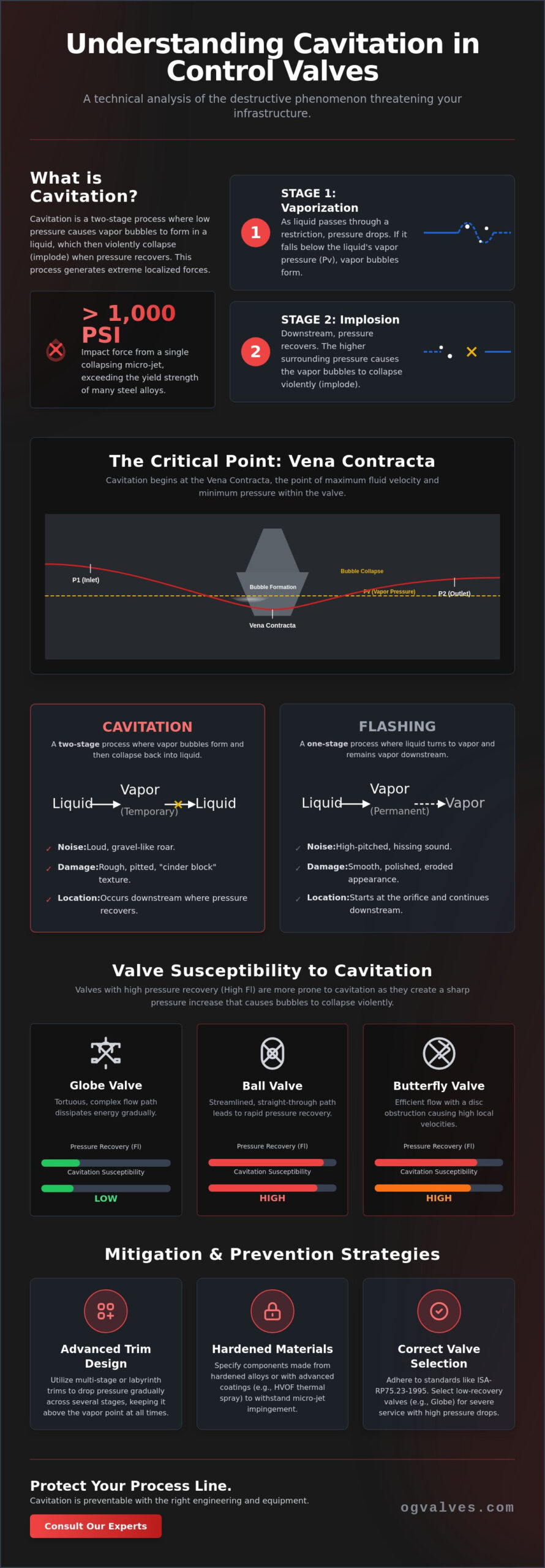
Did you know that the microscopic vapor bubbles collapsing within your process line generate localized micro-jets with impact forces exceeding 1,000 PSI? Understanding cavitation in control valves explained through fluid mechanics is the only way to prevent the rapid erosion and vibration that lead to catastrophic component failure. You’ve likely heard the signature gravel-like noise that signals a system’s decline, and you know these stresses aren’t just nuisances; they’re direct threats to your infrastructure’s structural integrity.
This guide provides a comprehensive technical analysis of cavitation mechanics based on the latest 2026 industry data. You’ll gain a clinical understanding of the Vena Contracta effect, learn to differentiate destructive cavitation from flashing, and identify high-performance material specifications like HVOF thermal spray coatings to extend component life. We’ll analyze the governing ISA-RP75.23-1995 (R2024) standards and provide a methodical framework for selecting globe, ball, or butterfly valves that withstand severe service conditions and minimize lifecycle costs.
Key Takeaways
- Identify the fluid dynamics at the Vena Contracta to predict precisely where vapor pressure drops initiate the cavitation cycle.
- Understand how asymmetrical bubble collapse generates high-velocity micro-jets that lead to severe material pitting and structural degradation.
- Utilize the technical principles of cavitation in control valves explained in this guide to differentiate it from flashing and ensure accurate diagnostics of system vibration.
- Implement engineering strategies such as multi-stage pressure drops and labyrinth trim designs to maintain operational stability in high-pressure applications.
- Optimize procurement by utilizing precise process parameters and adhering to ISA-RP75.23-1995 (R2024) standards for industrial valve selection.
The Physics of Cavitation: Vena Contracta and Vapor Pressure Dynamics
A rigorous examination of cavitation in control valves explained through fluid mechanics begins with Bernoulli’s principle. As a liquid medium passes through a restricted valve orifice, its velocity increases to maintain a constant mass flow rate. This acceleration results in a simultaneous drop in static pressure. If the local pressure within the valve body falls below the fluid’s specific vapor pressure (Pv), the liquid undergoes a phase change, forming vapor bubbles. This physical transition isn’t an instantaneous failure but the initiation of a complex, two-stage hydraulic event that threatens the structural soundness of the piping system.
The Vena Contracta is the most critical focal point in this process. It represents the specific location downstream of the physical valve seat where the flow stream reaches its minimum cross-sectional area and maximum velocity. Because velocity is at its peak here, the static pressure reaches its absolute lowest point within the valve assembly. If the pressure at the Vena Contracta drops below the vapor pressure of the liquid, vaporization is inevitable. The magnitude of this pressure drop is dictated by the valve’s internal geometry and the specific trim design, making precise engineering data essential for hardware selection.
The Two-Stage Process: Evaporation and Condensation
Cavitation is defined as a two-stage phenomenon occurring exclusively in liquid media. The first stage involves the formation of vapor bubbles as the fluid passes the Vena Contracta. The second stage occurs further downstream, where the flow area expands and velocity decreases, leading to pressure recovery. If the recovered downstream pressure (P2) exceeds the vapor pressure (Pv), the bubbles collapse violently. This implosion is a fundamental aspect of cavitation physics, generating localized shockwaves that can erode even the most durable stainless steel alloys.
The Pressure Recovery Coefficient (Fl)
Engineers utilize the Liquid Pressure Recovery Factor (Fl) to quantify a valve’s tendency to recover pressure downstream of the Vena Contracta. High-recovery valves, such as ball valves and butterfly valves, are characterized by streamlined flow paths that return a significant portion of the initial pressure. While efficient for flow, these designs are more susceptible to cavitation because they facilitate a rapid transition from vaporization to bubble collapse. In contrast, globe valves typically exhibit lower Fl values due to their tortuous flow paths, which dissipate energy and reduce the intensity of pressure recovery. Understanding these coefficients is vital when specifying equipment for high-pressure drop applications where operational reliability is mandatory.
The Mechanics of Valve Degradation: Micro-Jets and Material Pitting
The transition from thermodynamic phase changes to mechanical destruction is the most critical aspect of cavitation in control valves explained for maintenance engineers. While the formation of vapor bubbles occurs at the Vena Contracta, the damage happens downstream during the pressure recovery phase. This process is characterized by bubble implosion rather than explosion. As the surrounding static pressure rises above the fluid’s vapor pressure, the vapor bubbles collapse inward with extreme violence. If this collapse occurs in the center of the flow stream, the energy dissipates into the liquid. However, when bubbles collapse near the internal surfaces of the valve, the results are catastrophic.
The physics of an asymmetrical collapse near a solid boundary leads to the formation of a high-velocity micro-jet. Because the liquid cannot flow through the solid valve wall, the bubble deforms, and a jet of fluid pierces through the bubble’s center at supersonic speeds. Verified engineering data indicates these localized micro-jets generate impact forces that can exceed 1,000 PSI. This pressure level frequently surpasses the yield strength of common industrial materials, including hardened stainless steel alloys. The cumulative effect of millions of these microscopic implosions occurring every second leads to metallurgical fatigue and the rapid removal of base material.
Identifying Cavitation Damage
Cavitation damage possesses a distinct visual signature often described as a “cinder block” or “frosted” appearance. Unlike chemical corrosion, which typically shows uniform thinning or discoloration, cavitation creates deep, jagged pitting in concentrated areas. It’s also distinguishable from abrasive wear; while grit or scale erosion follows the flow path and smooths the metal, cavitation pitting appears as if the metal has been sandblasted or chipped away. These damage zones are most prevalent on the downstream side of valve plugs, seat rings, and the immediate exit throat of the valve body.
Systemic Consequences Beyond the Valve
The impact of cavitation isn’t confined to the valve trim. The acoustic signature of the process is a high-frequency, rattling noise resembling gravel or marbles passing through the pipe. This sound indicates a massive release of energy that translates into mechanical vibration. Such oscillations can lead to the loosening of structural fasteners and the premature failure of valve actuators, which are not designed to sustain continuous high-frequency stress. Selecting the appropriate globe valves with hardened trim from OG VALVES LTD. is a necessary step to protect downstream instrumentation, such as flow meters and pressure sensors, from the turbulent flow profiles and shockwaves generated by collapsing vapor bubbles.
Cavitation vs. Flashing: Identifying Different High-Pressure Drop Phenomena
Distinguishing between cavitation and flashing is essential for accurate system diagnostics and hardware specification. While the previous sections focused on the destructive collapse of vapor bubbles, flashing represents a fundamentally different thermodynamic outcome. Flashing occurs when the downstream pressure (P2) remains lower than the fluid’s vapor pressure (Pv). In this scenario, the vapor bubbles formed at the Vena Contracta do not implode. Instead, they remain in a gaseous state, resulting in a continuous two-phase flow of liquid and vapor at the valve exit. This distinction is a vital part of cavitation in control valves explained for engineers managing high-energy process loops.
The transition to a two-phase state creates “choked flow” conditions. As the liquid vaporizes, its specific volume increases significantly, which physically limits the mass flow rate through the valve orifice. Once the fluid reaches sonic velocity at the narrowest point of the trim, further reductions in downstream pressure will not increase the flow rate. This physical limit serves as a primary diagnostic indicator in the field. If increasing the pressure differential across the valve fails to yield a corresponding increase in throughput, the system has reached a choked condition, likely due to flashing or advanced cavitation.
Comparative Analysis of Flow Profiles
The primary difference between these phenomena lies in the pressure recovery profile. In cavitation, the pressure recovers above the vapor pressure line, causing the violent collapse of bubbles. In flashing, the pressure remains below the vapor pressure line throughout the downstream run. This leads to distinct damage patterns. Cavitation causes localized, jagged pitting from micro-jet impacts. Flashing results in smooth, shiny erosion. This “sandblasted” appearance is caused by the high-velocity vapor-liquid mixture scouring the internal surfaces of the valve body and downstream piping.
Engineering Implications for Selection
Standard anti-cavitation trim is ineffective against flashing because the phenomenon is a function of the system’s overall pressure levels rather than internal valve recovery factors. Since the vapor phase persists, engineers must prioritize erosion resistance rather than just surface hardness. This requires specifying materials such as Stellite overlays or tungsten carbide components. While globe valves are the standard for precise throttling, certain high-drop scenarios with high exit velocities may require specialized industrial ball valves equipped with erosion-resistant liners and reinforced seats to maintain long-term structural integrity.
Mitigation and Prevention: Advanced Trim Design and Material Specification
Effective engineering strategies for cavitation in control valves explained throughout this guide prioritize the management of the pressure drop across the valve trim. The most successful mitigation technique involves multi-stage pressure reduction. Instead of allowing a single, massive pressure drop that falls below the liquid’s vapor pressure, specialized trim designs partition the total differential into several smaller, controlled increments. This ensures that the local static pressure at every stage remains above the critical vapor pressure threshold, effectively preventing the formation of bubbles at the source.
Tortuous path and labyrinth trim designs represent another advanced approach. These components utilize a complex series of turns and restrictive channels to increase fluid friction. By dissipating energy through frictional resistance rather than high-velocity acceleration, these trims maintain a more stable pressure profile. Additionally, expanding flow areas within the trim can reduce exit velocities. This prevents the rapid pressure recovery that triggers the violent bubble collapse discussed in previous sections.
Material selection serves as a critical secondary defense when process conditions make cavitation unavoidable. Engineers specify hardened alloys and specialized coatings to withstand the mechanical stresses of micro-jet impacts. Common material upgrades include:
- 400-series stainless steel for improved hardness and wear resistance.
- Stellite overlays on seat rings and plugs to provide a robust barrier against pitting.
- Tungsten Carbide components for extreme severe service applications.
Anti-Cavitation Trim Technologies
Drilled hole cages are frequently employed to split the flow into numerous small streams. This design shifts the cavitation zone away from the valve walls and into the center of the flow, where bubble collapse is less destructive. While globe valves are the primary choice for these trims, engineers must also consider the recovery characteristics of high-performance butterfly valves in large-scale flow applications. These valves require careful trim characterization to manage the high-recovery profiles inherent to their geometry.
System-Level Mitigation Strategies
Hardware selection is only one part of the solution. System designers can mitigate cavitation by increasing downstream back-pressure using fixed orifices or by relocating the control valve to a lower-temperature zone in the process loop. Lowering the fluid temperature increases the margin between operating pressure and vapor pressure. Proper sizing is also mandatory; oversized valves operating at low lift are highly susceptible to localized cavitation at the seat. For critical infrastructure requiring precise pressure management, selecting high-specification globe valves from OG VALVES LTD. with custom-engineered trim is the most reliable method to ensure long-term operational safety.
Procuring Cavitation-Resistant Valves for Critical Industrial Applications
The successful procurement of severe service hardware depends on the translation of fluid dynamics into rigid data sheets. Having cavitation in control valves explained through mechanical theory is insufficient without precise process parameters. Procurement specialists must provide validated figures for inlet pressure (P1), outlet pressure (P2), operating temperature (T), and the fluid’s vapor pressure (Pv). These variables allow for the calculation of the cavitation index and the selection of an appropriate Liquid Pressure Recovery Factor (Fl). Inaccurate data at the bidding stage often leads to the installation of undersized or improperly trimmed globe valves; this results in unplanned outages within months of commissioning.
Adherence to global benchmarks like API 623 and ASME B16.34 ensures that the valve body and internal components meet the minimum wall thickness and pressure-temperature ratings required for high-stress environments. The 2024 reaffirmation of ISA-RP75.23-1995 (R2024) provides the current framework for evaluating a valve’s cavitation potential. OG VALVES LTD. facilitates technical compliance by aligning every specification with these international standards. We ensure that provided hardware, whether ball valves or needle valves, possesses the structural integrity to survive the localized micro-jets and shockwaves inherent to high-pressure drops.
Technical Specification Requirements
Mandatory data for cavitation analysis must include the critical pressure (Pc) of the media to account for thermodynamic properties near the fluid’s boiling point. Material integrity is verified through Positive Material Identification (PMI) testing. This ensures that the specified chrome-moly or stainless steel alloys are present in the final casting. In some system architectures, engineers must decide between specialized check valves and control valves to manage backflow-induced cavitation. While check valves prevent reverse flow, they don’t offer the throttling control required to manage the Vena Contracta effects discussed in previous sections. Precision-engineered needle valves may be specified for low-flow, high-pressure drop sampling lines where cavitation risk is high.
Global Supply and Technical Support
Managing lead times for anti-cavitation components requires a robust supply chain strategy. Specialized multi-stage trims and hardened Stellite components involve longer manufacturing cycles than standard gate valves. Partnering with a dedicated industrial valve supplier allows procurement teams to access technical test data and Fl coefficients during the design phase. This proactive approach supports fast-track technical procurement. It ensures that critical infrastructure projects meet their operational deadlines without compromising on engineering excellence or safety protocols. With the global control valve market projected to reach USD 11.5 billion in 2026, securing a reliable technical partner like OG VALVES LTD. is essential for maintaining operational output and regulatory adherence.
Optimizing Infrastructure Integrity Through Severe-Service Engineering
Managing high-pressure drop phenomena requires a clinical approach to fluid dynamics and material science. With the mechanics of cavitation in control valves explained, it’s clear that the transition from vapor bubble formation at the Vena Contracta to destructive implosion is a predictable hydraulic event. Mitigation depends on the implementation of multi-stage trim designs and the selection of hardened alloys capable of withstanding micro-jet impact forces. These engineering decisions serve as the primary defense against metallurgical fatigue and unplanned system downtime.
Reliable industrial operations require components that meet rigorous global standards. OG Valves maintains deep technical expertise in API 600 and ASME benchmarks; we provide specialized support for the oil, gas, and power generation sectors. Our global inventory features high-specification gate, ball, and globe valves designed for durability in severe-service applications. Consult with OG VALVES for specialized severe-service valve procurement to ensure your infrastructure adheres to the highest safety and performance requirements. Implementing these technical strategies secures the long-term operational output of your facility.
Frequently Asked Questions
What is the “gravel in the pipe” sound in a control valve?
This acoustic signature represents the massive energy release from millions of microscopic vapor bubbles imploding simultaneously. As the pressure recovers downstream of the Vena Contracta, these bubbles collapse. This process generates high-frequency shockwaves that resonate through the pipe wall. It’s a clinical indicator of active cavitation and signals that internal components are undergoing mechanical stress and material removal. Immediate inspection is necessary to prevent structural failure.
Can cavitation occur in gas or steam flow?
No, cavitation is strictly a liquid-media phenomenon. It requires a phase change from liquid to vapor and then back to liquid. In gas or steam service, high pressure drops lead to aerodynamic noise or choked flow, but the specific mechanics of bubble formation and collapse aren’t present. Understanding cavitation in control valves explained for liquid systems is essential for differentiating these distinct hydraulic and pneumatic challenges in industrial piping.
How does the pressure recovery coefficient (Fl) affect cavitation?
The Liquid Pressure Recovery Factor (Fl) quantifies how much the static pressure recovers downstream of the Vena Contracta. High-recovery valves, such as ball or butterfly valves, have lower Fl values, making them more susceptible to cavitation. A higher Fl indicates a valve design, like a globe valve, that dissipates more energy. This reduced pressure recovery helps keep the downstream pressure closer to the Vena Contracta pressure, potentially avoiding the vapor pressure threshold.
What is the difference between cavitation and flashing?
The primary difference lies in the downstream pressure state. In cavitation, the pressure recovers above the liquid’s vapor pressure, causing bubbles to collapse. In flashing, the downstream pressure remains below the vapor pressure, so the vapor bubbles persist as a two-phase flow. While cavitation causes jagged pitting, flashing results in smooth, shiny erosion. Both phenomena require different trim and material specifications to manage the specific degradation mechanisms effectively.
Which materials are best for resisting cavitation damage?
Hardened alloys and specialized coatings provide the highest resistance to micro-jet impacts. Engineers typically specify 400-series stainless steel, Stellite overlays, or tungsten carbide for severe service. These materials possess high yield strength and hardness, which are necessary to withstand the localized pressures exceeding 1,000 PSI generated during bubble collapse. Material selection is a critical secondary defense when process conditions cannot be altered to eliminate cavitation entirely.
How do multi-stage trims prevent cavitation from forming?
Multi-stage trims prevent cavitation by partitioning a single large pressure drop into several smaller, controlled increments. By managing the pressure gradient across multiple stages, the design ensures that the local static pressure never falls below the liquid’s vapor pressure at any point. This prevents the initial formation of vapor bubbles. This method is the most effective engineering strategy for cavitation in control valves explained in high-differential pressure applications.
Can cavitation be completely eliminated in high-pressure systems?
Yes, cavitation can be eliminated through precise trim engineering and system design, though it’s often more cost-effective to mitigate its effects. Using multi-stage pressure reduction or increasing downstream back-pressure can keep the fluid above its vapor pressure. In extreme high-pressure applications where some degree of cavitation is unavoidable, engineers focus on material hardening and shifting the cavitation zone away from critical valve surfaces to protect the valve body.
What happens if a cavitating valve is left in service?
Leaving a cavitating valve in service leads to rapid metallurgical failure and potential loss of containment. The continuous micro-jet impacts cause deep pitting that eventually breaches the valve body or destroys the trim’s sealing surfaces. This results in excessive leakage and loss of control accuracy. Such vibrations often cause secondary failures in downstream instrumentation, pipe supports, and valve actuators, which significantly increases overall lifecycle costs and safety risks.
 Responsive Menu