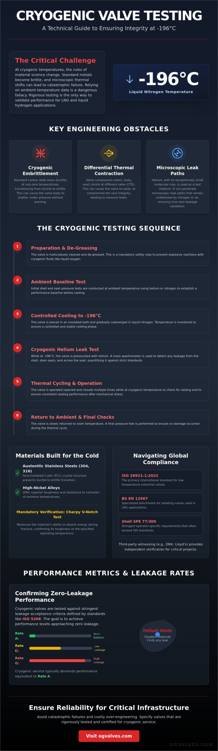
The difference between a functional industrial system and a catastrophic containment failure often rests on a few microns of seal integrity at -196°C. At these extreme temperatures, standard material behaviors become irrelevant as molecular structures shift and common metals turn brittle. Implementing a rigorous cryogenic valve testing procedure isn’t merely a regulatory hurdle; it’s the only definitive method to validate that a gate, ball, or globe valve can withstand the intense thermal contraction inherent in LNG and liquid hydrogen applications.
You likely understand that relying on ambient temperature data to predict performance in a cryogenic environment is a dangerous engineering fallacy. This guide provides a comprehensive technical breakdown of the testing protocols required to ensure industrial valve integrity down to -196°C, addressing the specific nuances of ISO 28921-1:2022 and BS 6364:1984. We’ll examine the critical testing sequence, from initial shell pressure checks to helium leakage acceptance criteria, ensuring your specifications meet the highest global benchmarks for safety and performance.
Key Takeaways
- Identify the core differences between ISO 28921-1 and BS EN 12567 to maintain international compliance across LNG and industrial gas infrastructures.
- Execute a precise cryogenic valve testing procedure that incorporates mandatory de-greasing and ambient pressure baselines to mitigate the risk of explosive fluid expansion.
- Evaluate helium mass spectrometry results against ISO 5208 leakage standards to confirm zero-leakage performance at temperatures as low as -196°C.
- Analyze how differential thermal contraction affects seat and seal integrity in gate, ball, and globe valves during extreme temperature fluctuations.
- Develop technical specifications that ensure high-stakes reliability for critical infrastructure while avoiding the costs associated with over-engineering.
Cryogenic service involves managing fluids at temperatures typically ranging from -50°C down to -196°C for liquid nitrogen and -269°C for liquid helium. To understand the physical constraints of these environments, engineers must first grasp the Fundamentals of Cryogenics. At these levels, standard thermodynamic assumptions fail. Material properties change fundamentally, necessitating a specialized cryogenic valve testing procedure to verify that the assembly remains functional under extreme thermal stress.
The primary engineering obstacle is cryogenic embrittlement. While carbon steel is a staple in standard industrial applications, it loses nearly all ductility at sub-zero temperatures. This transition from a ductile to a brittle state leads to sudden, catastrophic structural failure without prior deformation. Consequently, testing must confirm that the selected alloys maintain structural soundness and impact resistance when exposed to the working fluid. Failure to account for this transition can result in a valve body shattering under nominal pressure loads.
Helium serves as the preferred medium for these evaluations. Its molecular size is exceptionally small, which allows it to penetrate microscopic leak paths that would remain undetected by nitrogen or air. Because helium remains inert and gaseous at -196°C, it provides a stable and quantifiable metric for seat and shell integrity during the cooling phase. This precision is vital for high-stakes environments where even a minor leak could result in rapid gas expansion and subsequent pressure surges within the piping system.
Material Selection and the Charpy V-Notch Test
Austenitic stainless steels, specifically grades 304 and 316, along with high-nickel alloys, are the industry standard for cryogenic service due to their face-centered cubic (FCC) crystal structure. This structure prevents the ductile-to-brittle transition common in ferritic steels. Before a cryogenic valve testing procedure begins, technicians must verify Material Test Reports (MTRs) to ensure the specific heat lot has passed the Charpy V-Notch impact test. This test measures the energy absorbed by the material during fracture, confirming its toughness at the specified operating temperature. Without this verification, the risk of shell fracture during pressure testing increases significantly.
Understanding the Coefficient of Thermal Expansion (CTE)
Differential thermal contraction occurs when the various components of a valve, such as the stem, body, and seats, shrink at different rates during cooling. This physical phenomenon is governed by the Coefficient of Thermal Expansion (CTE). If the stem contracts less than the body, the valve may “lock” or “seize,” rendering it inoperable. Conversely, if the seat contracts more than the ball or gate, the seal integrity is compromised, leading to massive leakage. Rigorous CTE analysis ensures that the dimensional tolerances of industrial valves remain within acceptable limits to prevent operational failure during thermal cycling.
Regulatory Framework: BS EN 12567 and ISO 28921-1
The regulatory landscape for the cryogenic valve testing procedure is defined by a hierarchy of international standards and stringent operator-specific requirements. BS EN 12567:2000 serves as a specialized benchmark for isolating valves used in LNG applications, focusing on material suitability and verification tests. For broader industrial applications, the ISO 28921-1:2013 standard established the framework for low-temperature service, which has since been updated by the 2022 edition to reflect modern manufacturing capabilities. While these international standards provide a solid foundation, major energy operators often mandate compliance with Shell SPE 77/300. These internal specifications typically exceed ISO requirements, demanding more rigorous thermal cycling and lower leakage thresholds.
In high-criticality projects, third-party witnessing from organizations like Lloyd’s Register or DNV isn’t optional. These bodies provide independent verification that every step of the process has been executed according to the approved Quality Plan. This level of oversight ensures that the valve’s performance data is audit-ready and legally defensible in the event of an operational incident. For engineers, this validation is the final proof that the valve can handle the stresses of cryogenic fluid expansion without compromising the larger infrastructure.
Design Validation vs. Production Testing
A critical distinction exists between Design Validation Testing (DVT) and production pressure testing. Prototype testing requires a comprehensive evaluation of a valve range’s design limits, often involving multiple thermal cycles and maximum differential pressure scenarios to prove the design’s long-term viability. In contrast, batch testing protocols focus on maintaining consistency across a procurement order. While standard orders might allow for sampling, high-spec projects often specify 100% cryogenic testing for every unit. This rigorous approach ensures that every ball valve or gate valve delivered meets the exact safety parameters of the installation.
Fugitive Emission Standards (ISO 15848-1)
Cryogenic testing must also address fugitive emission control under ISO 15848-1. Extreme cold causes packing materials to contract, which can lead to hazardous leaks at the stem seal or packing gland. Testing protocols involve monitoring helium leakage during thermal cycling to ensure the valve maintains its emission class. Acceptance criteria are strictly defined; environmentally sensitive applications often require Rate A or Rate B compliance, which allows for virtually zero detectable leakage. Managing these seals requires precise engineering to maintain the necessary compression without causing stem seizure at -196°C.
The Step-by-Step Cryogenic Testing Sequence
The execution of a cryogenic valve testing procedure requires a methodical approach to eliminate variables that could skew leakage data or cause structural failure. Initial preparation begins with rigorous de-greasing and drying. Any residual hydrocarbons or moisture within the valve cavity will crystallize at -196°C, potentially damaging the seat or creating ice plugs that mask actual leak paths. Once cleaned, the valve undergoes an ambient pressure test. This step establishes a technical baseline for shell and seat integrity at room temperature, ensuring that no gross manufacturing defects exist before the resource-intensive cooling phase begins.
Gradual immersion into a liquid nitrogen bath follows the ambient baseline. Rapid temperature drops can induce thermal shock, leading to stress fractures in the valve body or bonnet. Technicians monitor the cooling rate to ensure a steady decline until the assembly is fully submerged and ready for stabilization.
Immersion and Temperature Stabilization
Achieving thermal equilibrium is non-negotiable for audit-ready results. The valve must be “soaked” at the target temperature until thermocouples indicate the core has reached the desired set point, typically -196°C. Monitoring must occur at multiple critical points, including the bonnet, the body, and the seat area, to confirm that no part of the assembly remains at a higher temperature. Safety during this phase is paramount. Handling liquid nitrogen requires specialized PPE and robust ventilation systems to manage nitrogen gas displacement, which poses an asphyxiation risk in confined testing environments.
The Pressurization Cycle
Once stabilization is confirmed, the pressurization cycle begins using high-pressure helium gas. Pressure is applied in incremental steps, allowing technicians to identify potential leaks before reaching the maximum design pressure. This methodical increase prevents sudden seal blowouts and provides a clearer picture of how the valve responds to increasing loads. Testing involves cycling the valve between open and closed positions to validate both shell integrity and the seat’s ability to achieve a positive shut-off. This is particularly critical when validating check valves, as these components must provide instantaneous back-flow prevention despite the significant material contraction occurring at sub-zero temperatures. The final measurement of helium leakage occurs at full design pressure, providing the definitive data required for project certification.
Quantitative data is the only valid metric for verifying the success of a cryogenic valve testing procedure. Engineers primarily distinguish between bubble immersion and helium mass spectrometry to identify seat and shell bypass. While bubble immersion provides a visual confirmation of leakage, it lacks the sensitivity required for high-pressure gas service. ISO 5208 establishes the benchmarks for these results, defining Rate A as zero visible leakage for the duration of the test. Rate B allows for a marginal, quantifiable volume of bypass, though most LNG specifications mandate Rate A to ensure maximum containment safety.
A common paradox in cryogenic testing is that low-pressure seat tests are often more difficult to pass than high-pressure evaluations. High-pressure gas forces the closure member against the seat, utilizing the fluid energy to enhance the seal. At low pressures, the valve relies entirely on the mechanical precision of the seat geometry and the inherent elasticity of the sealing materials. If a seal fails at 2 bar, it may appear tight at 100 bar; therefore, low-pressure integrity is the truest indicator of manufacturing quality. Technicians must also conduct a “warm-up” test as the valve returns to ambient temperature. This phase identifies leaks caused by unequal expansion rates as the metal components regain their original dimensions.
Helium Mass Spectrometry: The Gold Standard
Mass spectrometers provide the most granular data available, detecting helium atoms at a molecular level with sensitivities up to 10⁻¹⁰ mbar·l/s. The “vacuum hood” method is utilized to measure the total leakage rate of the entire valve assembly, while the “sniffing” method allows technicians to localize specific leak paths at the packing gland or flange gaskets. Helium mass spectrometry is required for ball valve validation in LNG service because it detects molecular-level bypass that traditional bubble immersion methods consistently miss. This technology ensures that fugitive emissions remain within the strict limits defined by ISO 15848-1.
Post-Test Inspection and Certification
Following the thermal cycle, a comprehensive visual inspection is mandatory to check for stress cracks, permanent deformation, or galling on the stem. The valve must demonstrate consistent torque requirements at both -196°C and ambient temperatures; any significant increase in operating force suggests internal component interference. All data points are compiled into a formal Factory Acceptance Test (FAT) report. This document serves as the permanent record of compliance for the end-user, proving that the component is fit for service in critical infrastructure. For projects requiring uncompromising reliability, you should specify valves with certified cryogenic test data to mitigate the risk of field failure.
Procuring and Specifying Tested Cryogenic Valves
Writing a procurement specification requires a precise alignment between operational risk and testing rigor. Over-specifying a cryogenic valve testing procedure for non-critical auxiliary lines leads to unnecessary expenditure; however, under-specifying for main LNG headers invites catastrophic failure. Engineers should define testing parameters based on the specific media, pressure class, and minimum design metal temperature (MDMT). Choosing a supplier with an established history in high-spec industrial components is the most effective way to ensure these protocols are executed without deviation. This background provides the necessary assurance that the valve’s internal geometry and material composition are optimized for sub-zero performance.
Fast-track delivery of pre-tested valves is essential for minimizing downtime in critical infrastructure projects. OG VALVES LTD. supports these global demands by maintaining a strategic inventory of components that have already undergone preliminary validation. This availability allows EPC contractors to meet aggressive schedules without compromising the depth of quality assurance required for -196°C service. It’s a clinical approach to supply chain management that prioritizes functional reality over generic stock fulfillment.
Selecting the Right Valve Type for Cryogenic Service
Application requirements dictate the selection between butterfly valves and gate valves. Triple-offset butterfly designs are often preferred for low-temperature throttling due to their reduced weight and superior seal performance under thermal cycling. Gate valves remain the standard for high-pressure isolation where a full-bore flow path is required. In both instances, extended bonnets are mandatory to move the packing gland away from the cryogenic fluid, protecting actuators from freezing and ensuring the stem seal remains within a functional temperature range. Cryogenic needle and plug valves must also utilize alloys with high nickel content to prevent the embrittlement discussed in earlier sections.
Global Logistics and Technical Support
A robust global supply chain is vital for sourcing specialized components that meet the rigorous cryogenic valve testing procedure standards. OG VALVES LTD. provides comprehensive technical documentation, including MTRs and third-party certified FAT reports, ensuring full audit compliance for the oil, gas, and power sectors. This data-centric approach simplifies the integration of new components into existing safety-instrumented systems. For specialized procurement needs or custom testing requirements, contacting the OG VALVES LTD. technical team ensures that your project specifications are met with clinical precision and engineering excellence. Reliable infrastructure depends on components that have been validated against the industry’s most demanding benchmarks.
Optimizing Infrastructure Integrity Through Technical Validation
The successful deployment of critical infrastructure in LNG and hydrogen sectors depends on the unwavering execution of a rigorous cryogenic valve testing procedure. This guide has detailed the necessity of material toughness verification via Charpy V-Notch testing and the precision of helium mass spectrometry in detecting molecular leaks at -196°C. Adherence to international standards like ISO 28921-1:2022 remains the primary safeguard against the catastrophic risks of material embrittlement and differential thermal contraction. Proper specification during the procurement phase ensures that every gate, ball, and globe valve is capable of maintaining seat integrity under extreme thermal stress.
OG VALVES LTD. supports these engineering requirements with technical expertise in API and ISO valve standards and an extensive inventory of high-specification components. Through global fast-track delivery capabilities, the organization provides the reliable hardware needed to maintain operational safety in the oil, gas, and power sectors. Request a technical consultation or quote for cryogenic valves from OG VALVES LTD. to secure a dependable partner for your critical infrastructure needs. Precision in testing today prevents failure in the field tomorrow.
Frequently Asked Questions
Why is liquid nitrogen used as the cooling medium for cryogenic valve testing?
Liquid nitrogen is the primary cooling medium because it remains stable at its boiling point of -196°C. This provides a consistent thermal environment that replicates the actual conditions of LNG and liquid nitrogen transportation. It is also an inert gas, which ensures that the valve internals remain free from oxidation or chemical reactions during the immersion and stabilization phases. Most industrial facilities favor it for its accessibility and predictable thermodynamic properties.
What is the difference between a low-temperature test and a cryogenic test?
Low-temperature testing usually applies to service between -29°C and -50°C, whereas cryogenic testing involves temperatures below -50°C. A specialized cryogenic valve testing procedure is required for the latter to address the ductile-to-brittle transition in metals. Cryogenic service also necessitates the use of austenitic stainless steels to ensure structural integrity at -196°C. These distinctions are critical for selecting the correct material grades and testing protocols for high-stakes industrial applications.
How long does a typical cryogenic valve testing procedure take to complete?
The duration of a cryogenic valve testing procedure typically ranges from 6 to 12 hours. This timeframe accounts for the necessary preparation, including de-greasing and ambient baseline checks. The majority of this period is dedicated to gradual cooling and thermal stabilization, ensuring the valve core reaches the target temperature before high-pressure helium testing begins. Large-bore valves with high thermal mass may require even longer soaking periods to reach a state of equilibrium.
Can any industrial valve be used for cryogenic service if it passes the test?
Passing a test doesn’t qualify a standard valve for cryogenic applications. The component must be engineered with specific design features like extended bonnets and pressure-relieving seats. Standard industrial valves lack the necessary clearances to manage the differential thermal contraction that occurs at -196°C, which leads to mechanical seizure regardless of initial test results. True cryogenic valves are built to specific standards like ISO 28921-1 to ensure long-term operational safety.
What are the most common reasons for a valve to fail a cryogenic test?
Failures often stem from seat bypass caused by unequal contraction of internal components. Stem seizure is another frequent issue, occurring when the clearance between the stem and the guide is insufficient for sub-zero operation. Residual moisture or hydrocarbons can also freeze within the seat cavity, preventing a positive shut-off and resulting in a failed leakage test. These failures demonstrate the importance of rigorous preparation and precise manufacturing tolerances in cryogenic engineering.
Is helium mass spectrometry mandatory for all cryogenic valve certifications?
While not universally required by every legacy standard, helium mass spectrometry is the mandatory benchmark for modern LNG and hydrogen specifications. It offers molecular sensitivity that bubble immersion cannot match. This method is essential for verifying Rate A leakage classes and ensuring compliance with ISO 15848-1 fugitive emission standards in environmentally sensitive installations. It remains the most reliable way to detect microscopic leak paths that could lead to catastrophic failure.
What is the purpose of an extended bonnet on a cryogenic valve?
The extended bonnet serves as a thermal buffer to protect the packing gland and actuator from extreme cold. It allows a column of vaporized gas to form, which insulates the stem seals and keeps them at a functional temperature. This design prevents the packing from becoming brittle and ensures the actuator operates without lubricant solidification or mechanical failure. Without this extension, the valve stem would likely seize or leak during standard operation.
How often should cryogenic valves be re-tested once in service?
Re-testing frequencies depend on the specific facility’s Risk-Based Inspection (RBI) protocols and local safety regulations. Most industrial operators perform partial stroke testing every 6 to 12 months to verify movement. Full functional testing and seat leakage verification are typically conducted during major plant turnarounds, which generally occur every 3 to 5 years. Maintaining a detailed log of these tests is required for audit compliance and long-term asset integrity management.
 Responsive Menu