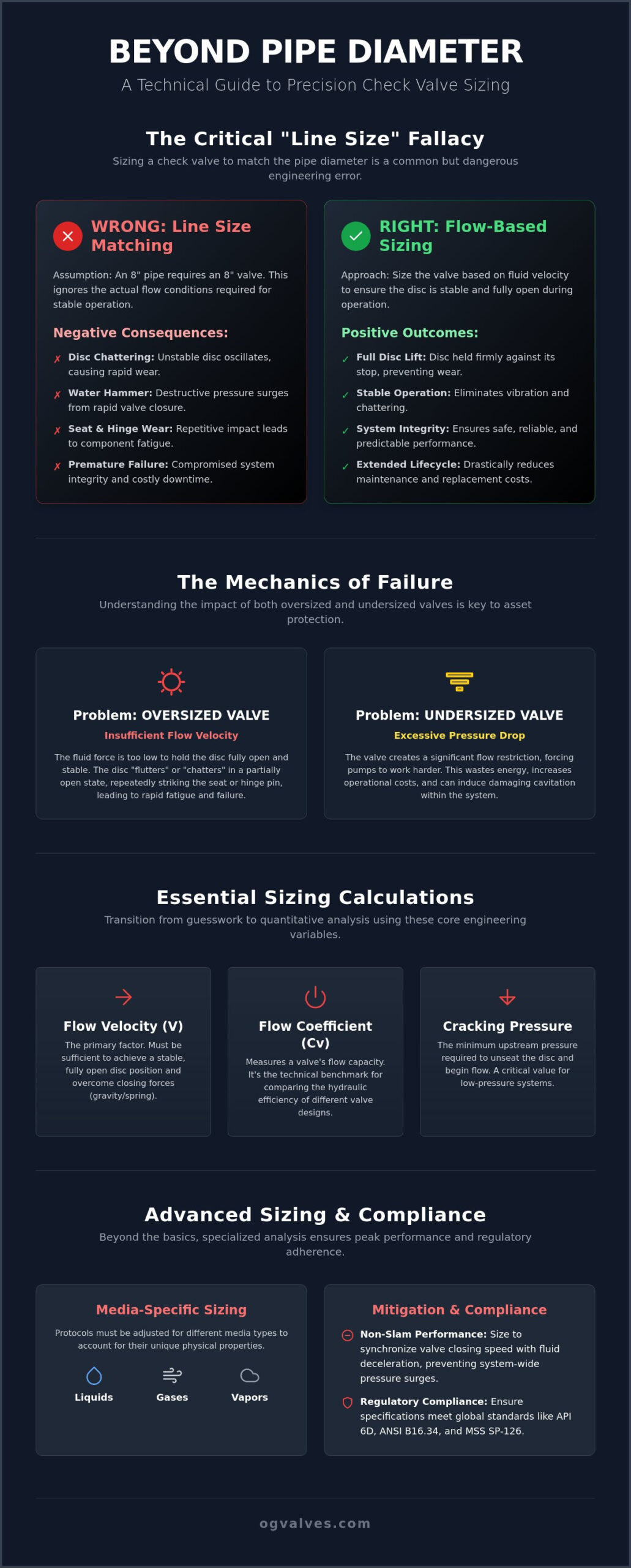
Selecting a check valve based solely on nominal pipe size is a critical engineering oversight that frequently leads to premature mechanical failure. You understand that maintaining system integrity requires more than just matching flange dimensions. Inconsistent flow velocities often cause disc chattering or severe water hammer; these issues compromise the structural soundness of your infrastructure. This industrial check valve sizing guide provides the technical framework necessary to calculate precise flow dynamics. By following these engineering protocols, you’ll ensure your valves reach full lift at minimum flow while remaining within API and ANSI pressure drop limits.
We will analyze the relationship between cracking pressure and disc stability, examine the updated requirements of MSS SP-126 refreshed in 2025, and outline the calculations required to mitigate surge risks in high-stakes environments. This methodical approach ensures that every specification aligns with global benchmarks for industrial safety and operational output. Mastering these technical requirements is the only way to eliminate mechanical instability and ensure long-term system integrity.
- Identify the operational risks of the line size fallacy and utilize this industrial check valve sizing guide to eliminate disc chattering and seat wear.
- Calculate Flow Coefficient (Cv) and cracking pressure requirements to ensure the valve disc achieves full lift under minimum system flow conditions.
- Apply media-specific sizing protocols for liquids, gases, and vapors to address compressibility factors and eliminate damaging hydraulic shock.
- Evaluate non-slam performance requirements to synchronize valve closing speeds with fluid deceleration, effectively mitigating system-wide pressure surges.
- Ensure regulatory compliance with international standards such as API 6D and ANSI B16.34 through rigorous technical specification and Positive Material Identification.
Selecting a check valve based on nominal pipe diameter is a frequent engineering error that compromises system stability. This is the “Line Size” fallacy. It assumes that if a pipe is 8 inches, the valve must also be 8 inches. However, check valves are flow-sensitive components, unlike gate or ball valves. This industrial check valve sizing guide emphasizes that functional performance depends on the fluid’s ability to maintain the disc in a stable, fully open position. If the valve is sized incorrectly, the system’s structural integrity is at risk.
When a valve is oversized for the actual flow rate, the media velocity is insufficient to hold the disc against its stop. This results in the disc oscillating or chattering within the flow stream. Conversely, an undersized valve creates an excessive pressure drop. This restriction forces the pumping system to work harder, leading to measurable energy losses and potential cavitation. Understanding check valve fundamentals is essential to recognize that the “Fully Open” position is a requirement for longevity, not a suggestion. Precision sizing ensures the valve operates within its intended design parameters.
The Mechanics of Disc Chattering
Disc chattering occurs when the dynamic force of the fluid is lower than the weight or spring force of the disc. Every valve design has a specific minimum velocity required to achieve a stable, fully open state. If flow stays below this threshold, the disc remains in a partially open, unstable position. Turbulence at these low rates causes rapid, repetitive impact between the disc and the seat or hinge pin. Engineers can identify this through audible metallic clicking or localized pipe vibration. These symptoms indicate that internal components are undergoing accelerated fatigue, which leads to catastrophic failure if left unaddressed.
Impact on System Lifecycle and Maintenance
Incorrectly specified valves are a primary driver of unscheduled maintenance. The cost of downtime in heavy industrial sectors often exceeds the initial procurement price of the component itself. Correctly sized valves ensure that the disc remains stationary during operation, which significantly reduces the frequency of seat replacement and hinge pin repair. For a broader perspective on selection criteria beyond sizing, consult our comprehensive guide to industrial check valves. Precise sizing is a strategy for long-term asset protection and operational output. It’s the difference between a system that lasts decades and one that requires constant intervention.
Engineering precision requires a transition from qualitative observations to quantitative verification. This industrial check valve sizing guide relies on three primary variables: flow coefficient, velocity, and cracking pressure. Flow Coefficient (Cv) is defined as the volume of 60°F water that flows through a valve at 1 psi pressure drop. This metric serves as the technical benchmark for comparing the hydraulic capacity of different valve designs. To calculate flow velocity (V), engineers must utilize the volumetric flow rate divided by the internal cross-sectional area of the pipe. Precision here is vital; even minor deviations in pipe ID measurements can skew velocity results by significant margins.
Understanding the flow regime is equally critical for system stability. The Reynolds number determines whether the fluid behaves in a laminar or turbulent manner. In most high-pressure industrial applications, turbulent flow is the standard, which influences the friction factor and subsequent pressure drop calculations. For a comprehensive overview of these principles, technical personnel should consult this Step-by-Step Guide to Valve Sizing. Determining the cracking pressure is the next stage in the calculation process. This is the differential pressure at which the valve begins to open, representing the threshold where upstream pressure overcomes the internal closing forces.
Calculating Pressure Drop (∆P)
The pressure drop across a check valve is a direct function of the flow rate and the valve’s Cv. The standard formula accounts for the specific gravity of the fluid, where heavier media or fluids with higher viscosities require more energy to move through the valve orifice. In power generation and petrochemical facilities, acceptable pressure drop limits are strictly defined by system efficiency requirements. Excessive ∆P leads to parasitic power losses and may indicate an undersized valve. Technical experts often consult with specialized manufacturers like OG VALVES LTD. to verify that calculated drops remain within permissible ANSI or API tolerances.
Cracking Pressure vs Full Lift
Cracking pressure is the initial opening state, but it doesn’t guarantee operational stability. Full lift occurs when the disc reaches its maximum travel limit, providing an unobstructed flow path and preventing chattering. Spring-loaded check valves typically require higher pressure differentials to overcome the mechanical resistance of the spring. Installation orientation also dictates these requirements. A valve installed in a vertical line with upward flow must overcome the weight of the disc plus any spring force, whereas horizontal installations rely primarily on fluid dynamics. Precision in these calculations ensures the valve doesn’t just open, but remains stable during operational cycles.

Precision in an industrial check valve sizing guide requires a rigorous assessment of media-specific physical properties. Sizing for liquids differs fundamentally from gases and vapours due to the contrast between incompressible and compressible flow regimes. Liquid systems are susceptible to hydraulic shock because the fluid’s high density and lack of compressibility provide no buffer against sudden velocity changes. Conversely, gas and vapour sizing must integrate the compressibility factor to account for volume expansion under varying pressure conditions.
Temperature-pressure de-rating is a mandatory step for high-temperature industrial media. As operating temperatures rise, the mechanical strength of the valve body and internal components decreases. Engineers must consult ASME B16.34 pressure-temperature rating tables to ensure the valve maintains its structural soundness at peak thermal loads. Material compatibility is equally vital in corrosive chemical processing. Metallurgical selection must prioritize alloys that resist localized pitting and stress corrosion cracking. Proper sizing is ineffective if the material fails to withstand the chemical environment of the media.
Liquid Flow Considerations
Managing viscosity is essential in heavy oil and petrochemical applications. High-viscosity fluids increase the drag coefficient on the valve disc, which necessitates a higher cracking pressure to initiate movement. Fluid inertia also dictates the required closing speed of the valve. The high mass of a liquid column means that any delay in valve closure allows significant reverse velocity to build, leading to damaging impact forces upon sealing. For detailed technical data on material benchmarks, engineers should refer to our industrial valves: the engineer’s comprehensive guide to selection and standards.
Gas and Vapour Sizing Dynamics
Gas valves often operate under sonic flow or choked flow conditions. This state occurs when the pressure drop across the valve reaches a critical ratio, causing the fluid velocity to reach the speed of sound at the vena contracta. Once choked, the mass flow rate will not increase despite further reductions in downstream pressure. Gas density fluctuations also impact disc stability; if the density is too low, the aerodynamic lift may be insufficient to hold the disc in a stable, fully open position. Applications involving superheated steam or high-pressure nitrogen require specialized trim designs to manage thermal expansion and ensure gas-tight shutoff during reverse flow events.
Water hammer represents one of the most destructive forces in pressurized piping systems. It occurs when a moving fluid column is forced to stop or change direction abruptly, converting kinetic energy into a high-magnitude pressure wave. This industrial check valve sizing guide identifies the synchronization of valve closing speed with fluid deceleration as the primary method for surge mitigation. If a valve closes too slowly, the fluid reverses direction, gaining momentum before the disc impacts the seat. This impact generates a pressure spike that can exceed the rated working pressure of the system, leading to ruptured pipes or damaged pump casings.
Standard swing check valves are often unsuitable for high-velocity systems due to their long travel path and high disc inertia. In contrast, nozzle check valves, also known as non-slam check valves, utilize a short-stroke design and spring-assisted closure. These features allow the disc to reach the seat almost at the exact moment the fluid velocity reaches zero, effectively preventing backflow before it gains momentum. Spring-assisted mechanisms and external dampeners are frequently integrated into high-stakes infrastructure to ensure the valve responds to the deceleration of the fluid column rather than waiting for flow reversal to occur.
The Criticality of Closing Time
The “Time to Close” metric is a fundamental specification in surge analysis. For nozzle check valves, this duration is minimized by the short travel distance of the disc and the proactive force of the internal spring. In multi-pump configurations, rapid closure is mandatory. If one pump fails or trips, the remaining active pumps continue to pressurize the common header. Without a correctly sized non-slam valve, the resulting backflow into the idle pump creates a severe slam. Technical specialists must select valves that provide a predictable response time to maintain system equilibrium during transient events. You can view our range of high-performance check valves to find specifications that meet these rigorous surge requirements.
Installation Geometry and Turbulence
Accurate sizing is often undermined by poor installation geometry. Turbulence generated by pumps, elbows, or transitions creates uneven pressure distributions across the valve disc. This leads to premature wear of the hinge pins and unstable opening characteristics. Industry standards typically recommend a minimum distance of five to ten pipe diameters of straight run upstream of the valve. If compact piping layouts prevent this, flow straighteners may be necessary to stabilize the velocity profile. Ensuring a uniform flow field is essential for the valve to function according to its calculated Cv and cracking pressure parameters.
Procurement of industrial check valves must align with the engineering calculations established in the previous sections of this industrial check valve sizing guide. Adherence to international standards is the primary form of validation for critical infrastructure. Specifications must strictly follow API 594 for wafer check valves, API 6D for pipeline applications, and ANSI B16.34 for pressure-temperature ratings. These benchmarks ensure that the valve’s mechanical design matches the calculated flow dynamics and pressure requirements. Utilizing the seventh edition of API RP 591, updated in February 2026, ensures that the valve qualification process meets modern safety benchmarks for high-stakes industrial environments.
Beyond dimensional accuracy, material integrity is a non-negotiable requirement. Positive Material Identification (PMI) serves as a critical verification step during the sizing and procurement process. It ensures that the metallurgical composition of the valve body and trim matches the specified alloy, preventing premature failure due to chemical incompatibility or thermal stress. OG VALVES LTD. integrates PMI into the quality control workflow to eliminate the risk of material substitution in high-specification environments where the cost of failure is absolute.
Quality Assurance and Certification Standards
Verifying pressure test certificates according to API 598 is a mandatory procurement protocol. These tests confirm the structural soundness of the valve shell and the tightness of the seat under high-pressure conditions. In sour gas environments, compliance with NACE MR0175 is essential to prevent sulfide stress cracking and hydrogen-induced damage. Each technical data sheet provided by OG VALVES LTD. reflects these rigorous material testing protocols, ensuring that the procured hardware meets the exact requirements of the original industrial check valve sizing guide calculations. The 2025 version of ASME B16.34 now includes Appendix H, which permits the use of materials compliant with ISO 10434, offering expanded options for global material sourcing without compromising safety.
Global Supply Chain and Technical Support
Minimizing operational downtime requires a robust global supply chain and rapid technical support. OG VALVES LTD. maintains the capability to handle large-scale industrial demands through fast-track delivery systems for critical infrastructure projects. Technical experts are available to consult on complex sizing scenarios where standard configurations don’t suffice. By leveraging comprehensive project management and global logistics, technical experts can secure rapid valve replacements that adhere to the highest engineering standards. Request a technical quote for high-specification check valves to initiate a consultation with our engineering team and ensure your system maintains its operational integrity.
Engineering a resilient piping network requires meticulous attention to flow dynamics and component specification. This industrial check valve sizing guide has outlined the technical necessity of moving beyond nominal pipe diameters to prevent mechanical instability. If you don’t account for actual flow velocity, system longevity is at risk. By prioritizing calculated flow coefficients and precise cracking pressures, you protect your infrastructure from the destructive effects of disc chattering and hydraulic surge. It’s the only way to ensure long-term reliability. Precision remains the benchmark for safety.
OG VALVES LTD. provides the technical expertise required for high-stakes industrial applications. As specialists in API 600, 6D, and 594 standards, we maintain an ISO 9001:2015 certified quality management system to guarantee structural soundness. We offer fast-track global delivery from our Northern Ireland facility to support your critical project timelines. Consult our technical team for precision valve sizing and global supply to secure components that meet your exact operational requirements. Implementing these precision standards today ensures your infrastructure remains robust for decades to come.
What happens if I size a check valve to match the pipe size?
Matching the valve to pipe size often results in an oversized component relative to the actual flow rate. This causes the disc to float in a partially open, unstable position, leading to chattering and localized vibration. This mechanical instability accelerates the wear of hinge pins and seats. Precision sizing ensures the disc remains pinned against the stop during operation, which prevents premature mechanical fatigue and ensures system integrity.
How do I calculate the minimum flow required for a check valve?
Minimum flow is calculated by determining the velocity needed to achieve full disc lift. This process involves analyzing the valve’s Cv alongside the specific gravity of the media. Manufacturers typically provide a minimum velocity figure, which often ranges between 1.5 to 3.5 m/s depending on the design. Referencing a technical industrial check valve sizing guide helps engineers verify these velocity thresholds against actual operational conditions.
Can a check valve be installed in a vertical pipe?
Vertical installation is permissible provided the sizing accounts for gravitational forces acting on the disc. For upward flow, the cracking pressure must overcome both the internal spring force and the physical weight of the disc assembly. Downward flow is generally not recommended for standard check valves. In such configurations, the valve may fail to close properly or achieve a leak-tight seal because it lacks sufficient backpressure-assisted closure.
What is the difference between cracking pressure and reseal pressure?
Cracking pressure is the minimum upstream differential pressure required to initiate disc movement off the seat. Reseal pressure is the specific pressure at which the valve closes and achieves a leak-tight seal. Reseal pressure is typically lower than the cracking pressure. This hysteresis is a critical factor in system design; it prevents the valve from cycling rapidly when operating near the cracking threshold.
Why is a non-slam check valve better for high-velocity systems?
Non-slam or nozzle check valves are superior for high-velocity systems because they utilize a short-stroke, spring-assisted design. This architecture allows the valve to close almost instantly when flow stops. By closing before flow reversal occurs, the valve prevents the fluid column from gaining momentum. This proactive closure effectively eliminates the pressure surges and mechanical shocks associated with water hammer in critical infrastructure.
How does fluid viscosity affect check valve sizing?
High fluid viscosity increases the pressure drop across the valve and can significantly slow the disc’s response time. Sizing calculations for heavy oils or polymers must utilize a corrected Reynolds number to account for laminar flow characteristics. This industrial check valve sizing guide emphasizes that failure to adjust for viscosity often leads to insufficient disc lift and increased parasitic power losses within the pumping system.
 Responsive Menu