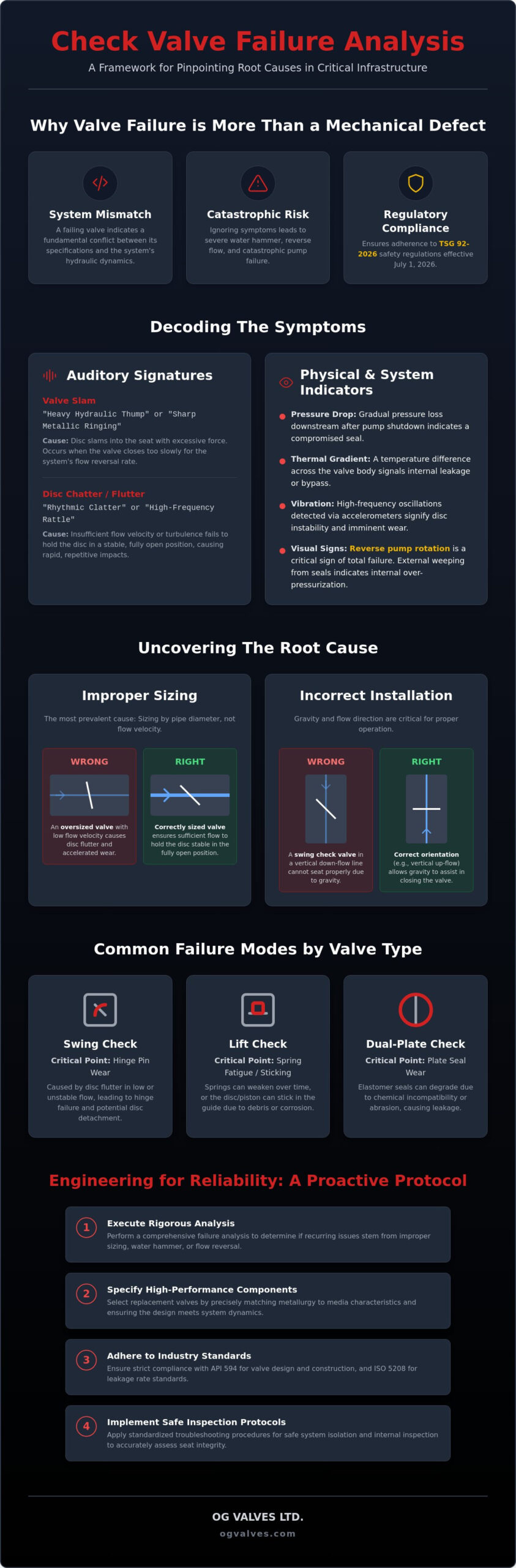
A failing check valve is rarely the result of an isolated mechanical defect. Instead, it serves as a clinical indicator that the valve’s physical specifications are fundamentally misaligned with the hydraulic dynamics of the piping system. Engineering teams often view recurring backflow or seat leakage as an unavoidable operational cost, yet ignoring these symptoms risks catastrophic pump failure and non-compliance with the stringent TSG 92-2026 safety regulations enforced as of July 1, 2026. This guide provides a rigorous framework for check valve failure analysis, enabling technical experts to pinpoint the exact failure modes compromising critical infrastructure.
Unplanned facility downtime represents a direct threat to operational safety and regulatory standing. By implementing engineering-led diagnostics, you’ll eliminate the risks of reverse flow and severe water hammer damage. We’ll examine the technical requirements of the 25th edition of API Specification 6D, evaluate failure modes such as disc slamming and chatter, and establish protocols for specifying replacement valves that match your specific system dynamics and material traceability requirements. This methodical approach ensures that every component meets the high-stakes demands of heavy industrial applications.
Key Takeaways
- Differentiate between auditory signatures, such as metallic clatter and hydraulic thumping, to pinpoint internal mechanical malfunctions before they escalate into system-wide failures.
- Execute a rigorous check valve failure analysis to determine if recurring issues stem from improper valve sizing or the destructive mechanics of water hammer and flow reversal.
- Identify design-specific failure modes across swing, lift, and dual-plate configurations, focusing on critical points like hinge pin wear and spring fatigue.
- Apply standardized troubleshooting protocols for safe isolation and internal inspection to accurately assess seat integrity and disc travel parameters.
- Specify high-specification replacement components by matching metallurgy to media characteristics and ensuring strict adherence to API 594 and ISO 5208 leakage standards.
Diagnostic Indicators of Industrial Check Valve Malfunction
Identifying the precise cause of operational instability requires a methodical approach to data collection. A comprehensive check valve failure analysis begins by interpreting the physical and acoustic data emitted by the valve during standard operation and shutdown cycles. These indicators aren’t merely operational nuances; they’re quantifiable symptoms of mechanical instability or hydraulic mismatch within the piping system. Technical experts must differentiate between localized component wear and systemic pressure anomalies to prevent catastrophic infrastructure damage.
Auditory signatures provide the most immediate diagnostic feedback. A sharp, metallic ringing usually indicates metal-to-metal seat impact, suggesting the disc is slamming into the seat with excessive force. Conversely, a rhythmic, lower-frequency clatter or rattle during steady-state flow points to disc flutter. This occurs when the flow velocity’s insufficient to hold the disc in the fully open position, leading to premature hinge pin wear and potential fatigue of the internal components. Thermal monitoring offers a clinical method for detecting internal bypass. In systems where the downstream media’s significantly hotter than the upstream fluid, a temperature gradient across the check valve body indicates seat leakage. If the upstream temperature rises toward downstream levels during pump idle, the seal’s compromised.
Vibration analysis using accelerometers can detect high-frequency oscillations indicative of disc flutter. These vibrations often precede mechanical failure, signifying that the disc is unstable within the flow stream. Furthermore, downstream pressure fluctuations during pump transitions reveal seal degradation. If the SCADA system records a gradual pressure drop on the discharge side after pump shutdown, the valve’s failing to maintain a bubble-tight seal, necessitating immediate inspection of the seating surfaces.
Auditory Diagnostics: Slamming vs. Chattering
Valve slam is a high-impact event occurring when a valve fails to close before the flow reverses. This results in a heavy hydraulic thump, often mistaken for general water hammer. It’s a symptom of a closing speed that’s too slow for the system’s deceleration rate. Chattering is a high-frequency vibration during flow. It’s caused by turbulence or low-velocity flow that fails to exert enough pressure to stabilize the disc, leading to rapid, repetitive contact between the disc and the stop or seat.
Visual and Operational Symptoms of Backflow
Reverse rotation of a centrifugal pump is the most critical operational indicator of total check valve failure. When the valve fails to seal, the downstream pressure forces fluid back through the pump, potentially causing catastrophic bearing and seal damage. Monitoring SCADA systems for unexplained pressure surge patterns during pump cycling also reveals seat degradation. External signs like weeping at the hinge pin or bonnet seal shouldn’t be ignored. These often indicate that internal stresses or pressure spikes have exceeded the design limits of the valve housing.
Root Cause Analysis: Why Check Valves Fail in Heavy Industry
A rigorous check valve failure analysis frequently reveals that mechanical breakdown is a secondary effect of fundamental system design errors. In heavy industrial environments, the most prevalent cause of premature degradation is improper valve sizing. Engineers often specify valves based on pipe diameter rather than actual flow velocity. When a valve’s oversized for a low-velocity system, the media doesn’t exert sufficient force to maintain the disc in a stable, fully open position. This results in constant oscillation, which accelerates hinge pin wear and leads to the eventual detachment of internal components.
Installation orientation also dictates operational longevity. Gravity plays a critical role in the return of the disc to the seat. For example, installing a standard swing check in a vertical-down flow configuration prevents the disc from seating correctly, leading to persistent backflow. Technical data from Reliability Estimation for Check Valves suggests that alignment with gravity and flow direction is paramount for achieving the designed MTBF (Mean Time Between Failure). When selecting high-specification components, consulting with a partner like OG VALVES LTD. ensures that the specified geometry aligns with the physical constraints of the facility infrastructure.
The Physics of Water Hammer and Disc Slam
Water hammer occurs when the kinetic energy of a moving fluid column is abruptly converted into pressure energy upon contact with a closed valve. This phenomenon is exacerbated by elastic column separation, where a vacuum pocket forms and then collapses, sending a massive pressure wave through the piping. The severity of the resulting disc slam is directly proportional to the distance the disc must travel to reach the seat after flow reversal begins. Water hammer is a kinetic energy conversion event where rapid deceleration generates destructive pressure transients. If the closure speed doesn’t outpace the flow reversal velocity, the valve becomes a primary failure point for the entire system.
Cavitation and Turbulence in Throttled Systems
Cavitation represents a distinct failure mode characterized by the formation and violent implosion of vapour bubbles on the disc and seat surfaces. This occurs when local pressure drops below the fluid’s vapour pressure, typically in high-velocity throttled sections. Technical inspections often reveal distinct pitting patterns on stainless steel internals, resembling a sponge-like texture. Turbulence also contributes to non-uniform flow distribution, particularly when valves are positioned too close to upstream elbows. This turbulent media creates uneven pressure across the disc face, inducing high-frequency vibrations that compromise the structural integrity of the seal and hinge assembly.
Component-Specific Failure Modes: Swing, Lift, and Dual Plate
Effective check valve failure analysis requires a granular understanding of how specific internal geometries interact with process media. Each design architecture, whether swing, lift, or dual plate, presents unique mechanical vulnerabilities that dictate its failure profile. Identifying these mode-specific weaknesses allows engineering teams to move beyond generic troubleshooting and implement precise remediation strategies that address the physical reality of the valve’s operation.
Nozzle or non-slam check valves, while superior in high-velocity applications, face their own set of challenges. Internal friction within the guide-way or obstructions from systemic debris can prevent the disc from traveling its full stroke. This results in increased pressure drops and a failure to reach the fully closed position during flow reversal. Unlike the multi-component assemblies of swing valves, nozzle checks rely on tight tolerances that are easily compromised by particulate-heavy media.
Mechanical Wear in Swing Check Internals
Hinge pin degradation remains the primary failure mode for swing check valves in heavy industrial service. This is frequently a direct consequence of disc flutter. When flow velocity is insufficient to hold the disc against the open-stop, the disc oscillates, leading to the physical elongation of hinge pin holes and eventual disc-to-seat misalignment. In horizontal piping runs, particulate entrapment at the base of the seat often prevents a bubble-tight seal. This differs significantly from the failure profiles seen in isolation components; for instance, a Technical Guide to Industrial Gate Valves highlights how isolation functions prioritize seat-to-wedge contact, whereas check valves must manage the dynamic stresses of autonomous, high-frequency movement.
Spring Fatigue in Lift and Dual Plate Designs
Lift and dual plate check valves rely heavily on internal springs to ensure rapid closure before flow reversal occurs. In high-temperature applications, material selection for these springs is critical. Standard alloys often suffer from stress-relaxation, leading to spring fatigue that manifests as a “stuck-open” or “slow-closing” valve. In dual-plate configurations, a broken torsion spring is a catastrophic event. Without the spring’s closing torque, the plates slam into the seat during flow reversal, often resulting in hinge pin galling or complete plate detachment. Diagnostic markers for piston check failure include inconsistent downstream pressure and an audible lack of the “click” associated with spring-assisted seating. Ensuring these components utilize Inconel or specialized stainless steel springs is a mandatory requirement for maintaining operational reliability in severe service environments.
Remediation of heavy industrial flow systems requires a transition from reactive maintenance to engineering validation. Before any physical intervention, technical teams must adhere to rigorous isolation and depressurisation protocols. In high-pressure environments, the energy stored in compressed media or static head can be lethal. Lock-out/tag-out (LOTO) procedures must be verified at the manifold level to ensure the valve body is completely atmospheric before the bonnet is removed for check valve failure analysis.
Once the valve is isolated, troubleshooting shifts to hydraulic verification. A common error in industrial systems is ignoring the minimum velocity required for full-disc lift. If the system flow is consistently below the valve’s designed Cv (Flow Coefficient) threshold, the disc will oscillate. This necessitates calculating the specific flow rates against manufacturer lift data. For existing swing check valves experiencing moderate slamming, external assistance like damping cylinders or weighted levers can be retrofitted. These mechanical aids control the closing rate, though they’re often secondary to addressing the underlying hydraulic mismatch.
Step-by-Step Internal Component Inspection
Internal diagnostics focus on quantifiable wear patterns. Technicians should use precision gauges to verify seat flatness and disc alignment tolerances. Any deviation from the manufacturer’s specified clearance can lead to persistent bypass. Spring-assisted designs require tension testing to ensure the closing force hasn’t degraded due to thermal stress or fatigue. A critical marker of high-velocity failure is “wire drawing,” a form of erosion that creates microscopic channels across the seating surface. This occurs when high-pressure media leaks through a minor gap, eventually cutting into the metal or elastomeric seal like a precision wire. If your system requires high-specification components to withstand these severe service conditions, request a technical consultation with our engineering team to review your application data.
Systematic Adjustments to Prevent Recurrence
Long-term remediation often involves architectural changes to the piping layout. Installing air release valves at high points in the system can mitigate the pressure surges that drive valve slam. If check valve failure analysis indicates that standard swing designs cannot handle the system’s rapid flow reversal, upgrading to non-slam nozzle check valves is the preferred engineering solution. These valves utilize short-stroke, spring-assisted discs that close before reversal reaches peak velocity. For complex projects involving stringent regulatory benchmarks, consulting specialist valve suppliers allows for the re-specification of internals based on actual operational output rather than original design assumptions.
Engineering for Reliability: Selecting Valves to Prevent Failure
The transition from check valve failure analysis to long-term system stability requires a shift toward rigorous engineering specifications. Selecting a valve based solely on nominal pipe size or initial capital expenditure frequently leads to premature mechanical degradation. Reliability in heavy industry depends on the precise alignment of metallurgy with process media characteristics. In high-temperature or corrosive environments, specifying standard carbon steel often results in rapid wall thinning or hinge pin seizure. Utilizing specialized alloys such as Duplex stainless steel or Inconel ensures that internal components maintain structural soundness under the stresses of high-frequency cycling and aggressive chemical exposure.
Adherence to global leakage benchmarks is the primary metric for validating valve performance. Modern industrial standards, specifically API 594 and ISO 5208, define the maximum allowable leakage rates for dual-plate and swing check configurations. For critical infrastructure where backflow risks threaten pump integrity or environmental safety, achieving a bubble-tight seal is mandatory. Engineering teams must verify that replacement components meet these stringent leakage classifications through documented factory acceptance testing. Integrating fast-track procurement into this workflow allows facility managers to replace compromised units with high-specification alternatives without extending unplanned downtime windows.
Regulatory Compliance and Testing Standards
Operational safety in 2026 is governed by increasingly strict traceability requirements. The enforcement of TSG 92-2026 mandates full material certificate traceability for all safety-critical pressure equipment. Implementing Positive Material Identification (PMI) during the procurement phase prevents corrosion-led failure caused by accidental alloy substitution. Technical experts should also verify compliance with API 6D for design standards and API 598 for valve inspection and testing protocols. These benchmarks ensure that non-return valves can withstand the rated pressure transients of the system. For a comprehensive overview of these design requirements, refer to this guide on Understanding Industrial Check Valves to align your hardware with current global benchmarks.
Global Supply Chain and Technical Specification
OG VALVES LTD. ensures minimal downtime through rapid technical assessment and a global logistics network optimized for critical infrastructure demands. Selecting the correct connection type, whether wafer, flanged, or butt-weld, is essential for maintaining the long-term reliability of high-pressure lines. Wafer designs offer space-saving advantages in compact skids, while flanged or butt-weld connections provide superior structural integrity in high-vibration power generation or oil and gas applications. OG Valves provides technical expertise to prevent application-led failure by verifying system dynamics before dispatch. This methodical approach to technical support ensures that every specified component is fit for its intended operational output, reducing the necessity for repetitive check valve failure analysis in the future.
Optimizing System Integrity through Engineering-Led Diagnostics
A successful check valve failure analysis transitions from identifying mechanical symptoms to implementing systemic engineering solutions. We’ve established that recurring malfunctions like disc slam and hinge pin wear are quantifiable results of hydraulic misalignment and improper component sizing. By prioritizing adherence to API 594 leakage standards and utilizing advanced metallurgy, facility operators can eliminate backflow risks and prevent catastrophic pump damage. Precision in the diagnostic phase directly dictates the longevity of the remediation strategy.
Maintaining critical infrastructure requires a partner that understands the high-stakes reality of industrial downtime. OG VALVES LTD. provides the technical expertise necessary for project-specific valve sizing and material selection across oil, gas, and power generation sectors. With an extensive inventory of API-certified valves and a global logistics network optimized for fast-track delivery, we ensure your facility remains compliant and operational. Consult with OG VALVES LTD. for technical specification and rapid valve supply to secure your facility’s long-term performance and safety.
Frequently Asked Questions
What are the most common signs of a failing industrial check valve?
Primary indicators include auditory signatures like metallic clatter, thermal gradients across the valve body, and reverse pump rotation during idle periods. A check valve failure analysis often reveals that downstream pressure drops on SCADA monitoring systems are early symptoms of seat bypass. If left unaddressed, these indicators precede catastrophic mechanical breakdown or total pump failure due to unmanaged backflow.
How can I tell if my check valve is chattering or slamming?
Chattering manifests as a high-frequency vibration or rhythmic rattling during steady-state flow, indicating that the disc is unstable. This usually occurs when flow velocity is insufficient to hold the disc against the open-stop. Slamming is a single, high-impact hydraulic thump occurring immediately after pump shutdown. It signifies that the fluid column reversed direction before the disc reached the seat, creating a destructive pressure surge.
Will an oversized check valve cause system failure?
Yes, an oversized check valve is a leading cause of mechanical fatigue in low-velocity systems. When the valve diameter exceeds the requirements of the actual flow velocity, the media cannot exert enough force to stabilize the disc. This results in constant oscillation, which accelerates hinge pin wear and leads to the eventual detachment of internal components. Proper specification must prioritize flow dynamics over pipe diameter.
How do I prevent water hammer caused by check valve closure?
Preventing water hammer requires the valve to reach the fully closed position the moment flow velocity reaches zero. Utilizing spring-assisted designs or non-slam nozzle check valves reduces the disc travel distance and increases closure speed. Installing air release valves at system high points and verifying that the valve’s Cv matches the system’s deceleration rate also mitigates the kinetic energy spikes associated with rapid flow reversal.
What is the difference between a swing check and a non-slam nozzle check valve in terms of failure risk?
Swing check valves carry a higher risk of slamming in high-velocity lines because they rely on gravity or flow reversal to close. This slow response time often results in high-impact seat contact. Non-slam nozzle checks utilize spring-assisted, short-stroke discs that close almost instantaneously as flow decelerates. This design significantly reduces mechanical fatigue and seat erosion, making it the preferred choice for critical infrastructure with rapid cycling.
Can a check valve be repaired while still in the pipeline?
Repairability is dictated by the valve’s body configuration, with top-entry designs allowing for internal component replacement without removing the valve from the line. While wafer-style valves generally require full removal for a check valve failure analysis, certain flanged swing and piston models feature removable bonnets. These allow technicians to inspect and replace springs, discs, or seals once the system is isolated and depressurised according to safety protocols.
What API standards govern the testing and failure limits of check valves?
API Std 594 and API 6D are the definitive standards for check valve design and performance. API 594 specifies dimensions and allowable leakage rates for dual-plate and wafer configurations. API 6D, with its 25th edition effective January 1, 2026, mandates rigorous manufacturing and quality control requirements. Pressure integrity and seat tightness testing protocols are further defined under API 598 to ensure compliance with global industrial safety benchmarks.
How does particulate matter affect different types of check valve mechanisms?
Particulate entrapment leads to abrasive erosion on seating surfaces and can physically obstruct guided mechanisms. In piston or lift check valves, debris accumulation often causes the disc to stick or prevents the spring from reaching full compression. In swing check valves, solids typically settle at the base of the seat, preventing a bubble-tight seal. This results in “wire drawing” erosion as high-pressure media is forced through the resulting gap.
 Responsive Menu