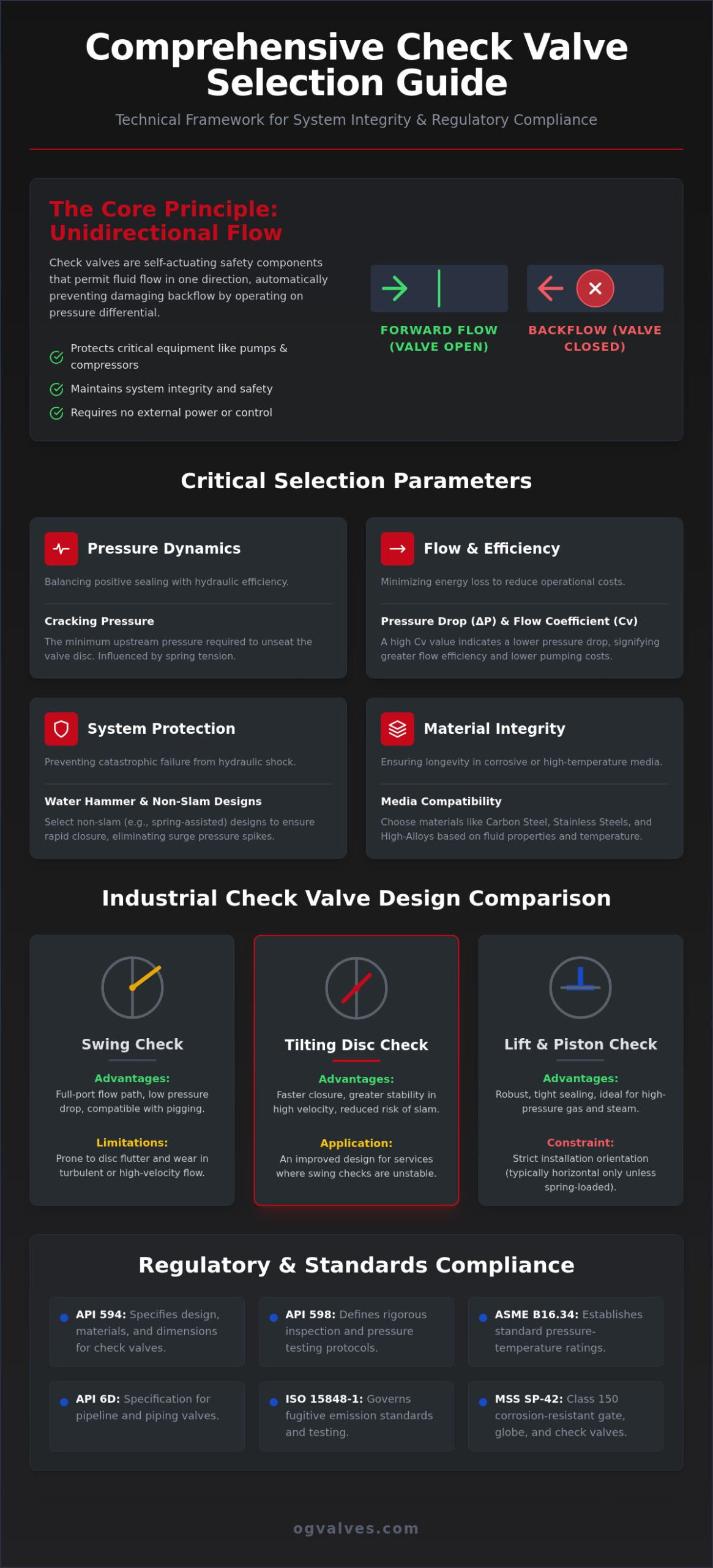
The enforcement of the TSG 92-2026 regulation on July 1, 2026, has fundamentally altered the compliance landscape for pressure-bearing equipment, making documentation traceability a critical operational requirement. For engineers managing high-velocity flows, an incorrect specification often leads to premature component wear or catastrophic system failure through water hammer. This comprehensive check valve selection guide establishes the technical framework necessary to evaluate valve performance against the updated MSS SP-42-2026 and ASME B16.34 standards.
You recognize that maintaining system integrity requires more than basic backflow prevention; it demands precise synchronization between material properties and hydraulic dynamics. We’ll provide the engineering data required to optimize valve longevity in aggressive environments, focusing on API 594 dual-plate configurations and the utilization of high-alloy materials for corrosive media. This analysis covers critical flow coefficients, fugitive emission standards under ISO 15848-1, and the rigorous testing protocols defined by the 11th Edition of API 598. By the conclusion of this technical review, you’ll possess the validated criteria to secure critical infrastructure and ensure full regulatory adherence across global supply chains.
Key Takeaways
- Identify the specific differential pressure requirements and self-actuating mechanisms necessary to maintain reliable backflow prevention in high-pressure systems.
- Apply this check valve selection guide to accurately determine cracking pressure and evaluate the influence of spring tension on hydraulic performance.
- Analyze material-media compatibility and temperature-induced mechanical property changes in carbon and stainless steels to prevent premature component failure.
- Implement surge mitigation strategies by selecting non-slam valve designs that synchronize valve closure with fluid deceleration to eliminate water hammer risks.
- Validate procurement decisions against international standards, including API 594, API 6D, and ASME B16.34, to ensure full regulatory compliance and operational safety.
Fundamental Mechanisms: Categorising Industrial Check Valve Designs
A check valve is a self-actuating safety component designed to permit unidirectional flow and prevent backflow within a piping system. It operates automatically based on the pressure differential across the valve internals. When the upstream pressure exceeds the cracking pressure and downstream resistance, the closure element moves to the open position. Conversely, a drop in upstream pressure or the onset of backflow forces the closure element against the seat. This fundamental mechanical response is essential for protecting pumps and compressors from reverse flow damage. Sealing remains the priority.
This check valve selection guide prioritizes the analysis of differential pressure as the primary driver of valve actuation. Industrial check valve designs are categorized by their geometric configuration and closure dynamics. The primary types include swing, lift, and dual-plate designs. Selection depends on flow velocity, media state, and allowable pressure drop. While some designs rely on gravity or flow reversal for closure, it’s often necessary to specify spring-assisted mechanisms. These springs accelerate the closing stroke, which significantly reduces the risk of hydraulic shock during pump shutdown. Reliability is a non-negotiable metric.
Swing and Tilting Disc Mechanisms
Swing check valves employ a hinged disc that swings away from the seat to allow flow. These are typically specified for large-diameter pipelines and low-velocity systems where a low pressure drop is required. Because they offer a full-port flow path, they’re compatible with pigging operations in midstream applications. However, swing mechanisms present mechanical risks in turbulent conditions. High-velocity or fluctuating flows cause disc fluttering. This leads to premature hinge pin wear and seat degradation. Tilting disc variants address these issues by centering the pivot point, allowing for faster closure and improved stability in high-velocity flows.
Lift and Piston Check Valve Performance
Lift check valves utilize a guided piston or disc that rises vertically from the seat. This design is exceptionally robust in high-pressure environments where tight sealing is a priority. Engineers prefer lift checks for steam, air, and high-velocity gas services due to their stable internal guiding and minimal disc travel. Unlike swing designs, lift valves are subject to strict orientation constraints. Standard globe-style lift checks must be installed in horizontal lines. If vertical installation is required, a spring-loaded piston design is mandatory to ensure the disc returns to the seat. It’s a critical safety distinction. Failure to respect these orientation limits results in valve malfunction or total system bypass.
Hydraulic Selection Parameters: Cracking Pressure and Flow Dynamics
Cracking pressure is the precise upstream pressure required to initiate disc movement and break the seal against the valve seat. In this check valve selection guide, we distinguish between the initial cracking pressure and the pressure required to achieve a fully open position. For spring-loaded designs, the spring’s tension directly dictates this value. While a higher cracking pressure ensures a more positive seal, it also increases the total pressure drop across the system. Engineers must balance these variables to maintain hydraulic efficiency while preventing backflow.
Pressure drop, or Delta P, represents the energy loss as fluid passes through the valve body. This loss translates directly into increased pumping costs over the system’s operational lifespan. To quantify this, the Flow Coefficient (Cv) is utilized to define the volume of fluid a valve can handle at a specific pressure differential. Adherence to the ASME B16.34 standard provides the necessary pressure-temperature ratings to ensure the valve body and internals withstand these hydraulic forces. Selecting a valve with an optimized Cv ensures that the system operates within its designed energy parameters. For complex high-pressure configurations, consulting with technical specialists regarding API-compliant check valves is recommended to verify performance data.
Minimum Flow Requirements
Operating a system below its minimum flow velocity induces a mechanical failure mode known as chatter. This phenomenon occurs when the fluid force is insufficient to hold the disc in a stable, fully open position. The resulting high-frequency oscillation against the valve seat and stops leads to rapid hinge pin fatigue and sealing surface degradation. The ratio of disc mass to fluid velocity determines the threshold for dynamic stability in unassisted swing designs. Ensuring the valve remains fully open during peak and nominal service is essential for preventing internal component failure.
Sizing vs. Pipe Diameter
Matching a check valve solely to the nominal pipe size often results in poor system performance. If the actual flow rate is low relative to the pipe diameter, an oversized valve won’t reach its full-open state. This restriction increases turbulence and mechanical wear. Precise sizing requires matching the valve’s flow capacity to the actual system requirements rather than the existing infrastructure’s dimensions. Proper selection ensures the disc stays stable, reducing the risk of premature maintenance cycles and optimizing the overall safety of the fluid transport network.

Material integrity is the primary determinant of valve service life in aggressive processing environments. This check valve selection guide emphasizes that chemical compatibility between the process media and the valve trim is non-negotiable. Carbon steel components often exhibit reduced impact toughness at sub-zero temperatures, while standard stainless steels like 304 may experience rapid pitting in chloride-rich media. Selecting 316L stainless steel provides superior corrosion resistance, though it typically incurs a 20-30% cost premium over standard grades. Engineers must also evaluate the risk of galvanic corrosion in multi-material assemblies. When a stainless steel disc operates within a carbon steel body in an electrolytic medium, the resulting electrochemical reaction accelerates structural degradation. Compatible material pairings are essential for long-term reliability.
Temperature-induced changes in mechanical properties further complicate selection. High-temperature service reduces the allowable working pressure of the valve body, a relationship defined by the pressure-temperature ratings in ASME B16.34. For leak-tight requirements, elastomeric seats offer superior sealing but are limited by thermal degradation. Metal-to-metal seating is mandatory for high-temperature applications, though it accepts a higher allowable leakage rate under API 598. Technical documentation, such as the DOE Engineering Symbology Handbook, provides the foundational diagrams necessary to identify these material requirements within complex piping and instrumentation diagrams (P&IDs).
Alloys for Extreme Environments
Offshore and high-salinity environments demand the use of specialized alloys like Super Duplex or Monel to prevent chloride stress corrosion cracking. OG VALVES LTD. prioritizes the supply of these high-alloy materials for critical infrastructure where standard steels fail. In hydrocarbon processing, NACE MR0175 compliance is mandatory for environments containing hydrogen sulfide (H2S) to prevent sulfide stress cracking. For abrasive media or high-velocity steam, hard-facing the seating surfaces with Stellite is a standard requirement. This cobalt-chromium alloy provides the necessary hardness to resist erosion and galling under extreme mechanical stress.
Sealing and Gasket Specifications
The choice between PTFE and graphite seals depends on the intersection of chemical resistance and thermal limits. PTFE is the benchmark for chemical inertness but fails in applications exceeding 200°C. Graphite remains the industry standard for high-temperature and fire-safe service. Media viscosity also influences seat selection; high-viscosity fluids may prevent resilient seats from achieving a full seal, necessitating higher cracking pressures. To ensure compliance with the TSG 92-2026 regulation, every component must be backed by Mill Test Reports (MTRs). Applying a rigorous check valve selection guide ensures that material traceability is maintained from the foundry to the final installation site.
System Protection: Non-Slam Characteristics and Surge Mitigation
The physics of valve slam is defined by the relationship between fluid deceleration and the mechanical closure speed of the valve internals. When a pump shuts down, the fluid column begins to decelerate and eventually reverses. If the check valve hasn’t fully seated before this reversal occurs, the reversing fluid slams the disc into the seat. This creates a high-magnitude pressure spike known as water hammer. This check valve selection guide identifies pump discharge lines and high-head systems as the primary areas requiring surge mitigation. For these high-stakes environments, short-stroke, spring-assisted dual-plate valves offer a significant mechanical advantage. By reducing the distance the disc must travel, these valves minimize the time available for reverse flow to gain momentum. Nozzle check valves, or axial flow valves, provide the highest level of protection by utilizing a venturi-shaped body and a low-inertia disc to achieve near-instantaneous closure in both liquid and high-pressure gas manifolds.
Dynamic Response and Closure Speed
Comparing the closing times of standard swing checks against axial flow designs reveals a critical performance gap. Swing checks rely on gravity and flow reversal, which often results in delayed closure and subsequent system shock. Axial designs utilize internal springs to initiate closure the moment flow velocity drops. Spring-assisted closure mechanisms ensure that the valve reaches the fully seated position before the reverse flow velocity can reach a peak magnitude. In certain large-diameter applications, external levers and hydraulic dampeners are employed to control the closure rate, though these require frequent maintenance to ensure reliability.
Noise and Vibration Control
Excessive noise and vibration within a piping system are typically indicators of severe turbulence or mechanical chatter. Proper valve selection mitigates these acoustic issues by ensuring the disc remains stable during all phases of operation. Turbulence doesn’t just create noise; it causes secondary vibration that accelerates the fatigue of welds and supports. In automated systems, integrating check valves with industrial valve actuators allows for real-time monitoring of valve position and system pressure. This data is vital for predictive maintenance and ensuring the long-term safety of the infrastructure. For assistance in matching valve dynamics to your specific hydraulic profile, request a technical consultation for surge protection solutions with our engineering team.
Selection Framework: Regulatory Standards and Procurement Strategy
API 594 governs the design of wafer, lug, and double-flange check valves, prioritizing compact face-to-face dimensions for refinery and chemical plant layouts. In contrast, API 6D provides the specification for pipeline valves, mandating more rigorous design criteria for long-distance transport infrastructure. This check valve selection guide requires engineers to distinguish between these standards based on the criticality of the installation. While API 594 is suitable for process piping, API 6D is the benchmark for midstream assets. All selections must align with the pressure-temperature ratings defined in ASME B16.34. These ratings dictate the maximum allowable working pressure across the valve’s full thermal range. Precision is the baseline for safety.
End connection selection is determined by maintenance frequency and piping stress. Flanged connections offer ease of replacement but add significant weight. Wafer and lug configurations minimize the footprint and are standard for API 594 designs. For high-pressure, high-temperature steam or hazardous media, butt-weld ends are specified to eliminate potential leak paths at the flange gasket. In refinery applications, fire-safe testing according to API 6FD is a mandatory requirement. This standard ensures the valve maintains its sealing integrity during and after exposure to an external fire, preventing the escalation of a localized incident. Failure to comply with these benchmarks introduces unacceptable risk into the infrastructure.
Quality Assurance and Technical Documentation
High-stakes procurement demands absolute material certainty. Positive Material Identification (PMI) is utilized to verify the alloy composition of the valve body and trim before shipment. This process prevents the accidental installation of sub-standard materials in corrosive environments. Every valve must undergo hydrostatic shell testing and pneumatic seat leakage testing as prescribed by API 598. Consulting with a specialized industrial valve supplier ensures that these technical specifications meet the unique demands of complex projects. Traceability documentation, including Mill Test Reports (MTRs), is now a regulatory necessity under the TSG 92-2026 standard. It’s the only way to guarantee performance.
Optimising Global Supply Chain Lead Times
Strategic sourcing is essential for managing the lead times of long-lead items, particularly for planned shutdowns or turnarounds (TAR). High-alloy check valves in Super Duplex or Monel often require extended manufacturing windows. Relying on global fast-track delivery services minimizes critical industrial downtime when unexpected failures occur. For a deeper technical analysis of internal geometries and seat configurations, refer to our comprehensive guide to industrial check valves. Proactive procurement planning ensures that API-compliant assets are available to meet the rigorous schedules of heavy industrial infrastructure projects. Reliability begins with the specification.
Securing Infrastructure Through Technical Precision
Successful implementation of this check valve selection guide ensures that hydraulic response times and material integrity are precisely matched to the operational demands of high-stakes environments. Engineers must prioritize compliance with updated standards such as API 594 and the TSG 92-2026 regulations to maintain system safety and full documentation traceability. Balancing non-slam characteristics with the pressure-temperature ratings defined in ASME B16.34 remains the industrial benchmark for preventing catastrophic water hammer and premature component fatigue. OG VALVES LTD. supports these engineering requirements with an extensive API-compliant inventory and specialist technical guidance for heavy industry applications.
Efficient procurement strategies rely on the intersection of technical validation and global fast-track logistics. Request a Technical Quote for Industrial Check Valves to secure high-specification components for your next project or planned shutdown. Precise selection today guarantees the operational longevity and regulatory adherence of your critical infrastructure for the long term.
Frequently Asked Questions
What is the primary difference between a swing check valve and a lift check valve?
The primary difference lies in the motion of the closure element and the resulting flow path. A swing check valve utilizes a hinged disc that rotates away from the seat, whereas a lift check valve employs a piston or disc that moves vertically. Swing designs are optimized for large-diameter, low-velocity pipelines. Lift designs provide superior sealing performance in high-pressure steam or gas services. Orientation limits are stricter for lift valves.
How do I calculate the required cracking pressure for my system?
Calculating cracking pressure requires identifying the sum of the static head pressure and the mechanical resistance of the closure element. In spring-assisted designs, the spring rate is the dominant variable. This check valve selection guide emphasizes that the minimum upstream pressure must exceed the downstream resistance plus the force required to initiate disc travel. Accurate calculation prevents system stagnation while ensuring the valve achieves a full-open state during nominal flow conditions.
Why is a dual-plate check valve often considered “non-slam”?
Dual-plate designs are categorized as non-slam because they utilize a short-stroke disc and spring-assisted closure dynamics. The spring forces the plates toward the seat the moment upstream velocity decreases, ensuring closure occurs before the fluid column reverses. This synchronization eliminates the high-magnitude pressure spikes associated with traditional swing checks. By preventing reverse flow velocity from peaking, the dual-plate configuration protects sensitive downstream infrastructure from the mechanical shock of water hammer.
Can check valves be installed in vertical piping runs?
Check valves can be installed in vertical runs provided the design accounts for gravitational forces on the closure element. For upward flow, spring-loaded piston or dual-plate designs are mandatory to ensure the disc returns to the seat during pump shutdown. Downward flow applications are technically challenging because gravity opposes the closing mechanism, often leading to leakage. Engineers must verify that the selected valve’s cracking pressure is sufficient to overcome the fluid’s static head.
What are the risks of using an oversized check valve?
Oversized valves suffer from mechanical chatter, a condition where the fluid velocity is insufficient to maintain a stable, fully open disc position. This results in high-frequency oscillation of the internals against the stops and seat. Chatter causes rapid fatigue of hinge pins and spring mechanisms, leading to catastrophic internal failure. Matching the valve’s flow coefficient (Cv) to the actual system flow rates is a critical step in any check valve selection guide to ensure longevity.
Which API standards govern the design of industrial check valves?
The design and manufacturing of industrial check valves are primarily governed by API 594 and API 6D. API 594 covers the specifications for wafer, lug, and double-flanged check valves used in process piping. API 6D is the standard for pipeline valves in midstream infrastructure. Additionally, API 598 defines the mandatory inspection and testing protocols, including hydrostatic shell and seat tests, to verify the mechanical integrity and sealing performance of the assembly.
How does media viscosity affect check valve selection?
High media viscosity increases the pressure drop across the valve and slows the mechanical response of the closure element. Thick fluids create additional drag on the disc, which can delay closure during flow reversal and increase the risk of surge. Viscous media also interferes with the effectiveness of resilient or elastomeric seats, potentially preventing a leak-tight seal. Selection must prioritize designs with higher cracking pressures or specialized internal geometries to maintain hydraulic efficiency.
What maintenance is required for check valves in high-cycle applications?
Maintenance for high-cycle check valves focuses on the early detection of mechanical fatigue and erosion. Technicians should conduct regular acoustic monitoring to identify chatter and perform visual inspections of the hinge pins, springs, and seating surfaces. In high-velocity systems, Stellite hard-facing should be checked for pitting or galling. Replacing worn springs and seals before failure is essential for protecting the integrity of the broader piping network and avoiding unplanned industrial downtime.
 Responsive Menu