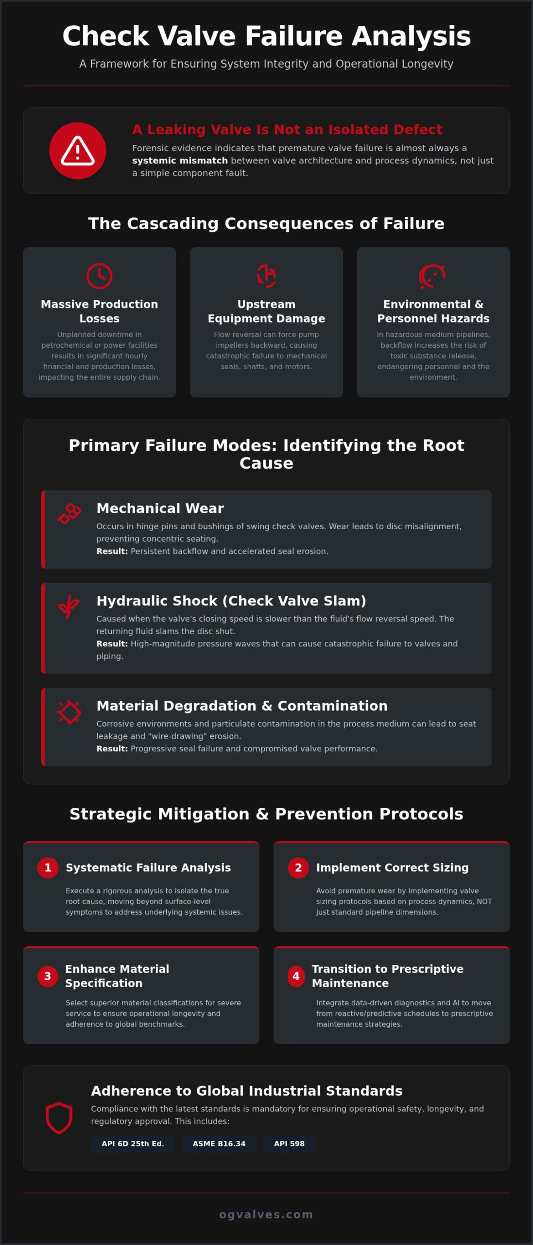
Most industrial operators treat a leaking check valve as an isolated component defect; however, forensic evidence suggests that premature mechanical degradation is almost always a systemic mismatch between valve architecture and process dynamics. When a high-pressure system experiences backflow or water hammer, the resulting unplanned downtime and safety risks can compromise entire infrastructure projects. Conducting a rigorous check valve failure analysis isn’t merely a reactive maintenance task. It’s a critical engineering requirement to ensure compliance with the latest API 6D 25th edition specifications and ASME B16.34 standards.
You’re likely aware that corrosive environments and high-cycle applications demand more than standard material specifications. This guide provides a comprehensive engineering framework for diagnosing specific failure modes, from disc slam to seat erosion, while mitigating operational risks. We’ll examine how to identify root causes of mechanical failure, select superior material classifications for severe service, and transition from predictive to AI-driven prescriptive maintenance schedules. By aligning your procurement and maintenance protocols with global regulatory benchmarks, you can ensure long-term industrial valve longevity and structural soundness.
Key Takeaways
- Execute a systematic check valve failure analysis to isolate root causes such as mechanical wear, hydraulic shock, and material degradation in high-pressure environments.
- Identify the specific mechanics of ‘Check Valve Slam’ to prevent backflow-induced pump damage and ensure the structural integrity of critical infrastructure.
- Avoid premature component wear by implementing correct valve sizing protocols rather than relying on standard pipe line sizing.
- Transition to prescriptive maintenance strategies through structured visual inspection and the integration of data-driven diagnostic methodologies.
- Enhance operational longevity by specifying materials that adhere to updated global benchmarks, including the API 6D 25th edition and ASME B16.34 standards.
The Critical Role of Check Valve Failure Analysis in Industrial Systems
The Check valve serves as the primary mechanical safeguard against unidirectional flow reversal within high-pressure piping systems. While often perceived as a simple passive component, its failure frequently triggers a cascade of systemic degradation. A rigorous check valve failure analysis is the only reliable method to determine whether a malfunction stems from incorrect material selection, improper sizing, or unforeseen process dynamics. In heavy industrial sectors, such as oil and gas or power generation, the failure of a single check valve can compromise the structural integrity of multi-million dollar assets. This forensic approach is essential for maintaining long-term operational integrity and reducing the total cost of ownership (TCO) across the facility lifecycle.
Identifying the Cost of Unplanned Downtime
The economic consequences of valve failure extend far beyond the procurement cost of a replacement unit. In petrochemical refining or power facilities, unplanned downtime results in massive hourly production losses. A malfunctioning check valve often causes secondary damage to upstream centrifugal pumps. When flow reverses, it forces the pump impeller to rotate backward, leading to mechanical seal failure, shaft misalignment, or motor burnout. Safety risks also escalate when reverse flow occurs in hazardous medium pipelines, increasing the potential for environmental contamination and personnel exposure to toxic substances.
Adherence to Global Industrial Standards
Regulatory compliance is a mandatory requirement for maintaining operational safety and licenses. Standards such as API 598 define the rigorous testing protocols for valve leakage and shell integrity. Similarly, ASME B16.34 provides the pressure-temperature ratings and material requirements essential for industrial safety. During a forensic check valve failure analysis, engineers rely on Material Test Reports (MTRs) to verify that the component’s chemical composition and mechanical properties align with the original design specifications. This verification ensures the valve can withstand specific hydrodynamic stresses without suffering catastrophic structural failure.
Implementing a structured failure analysis protocol allows organizations to transition from reactive repairs to a data-driven reliability strategy. By understanding the specific environmental stressors that lead to component fatigue, procurement specialists can select superior material specifications that exceed the baseline requirements of global benchmarks. This methodical focus on engineering excellence ensures that every valve in the infrastructure acts as a dependable partner in critical operations, rather than a point of potential failure. Relying on technical expertise and high-spec inventory from established global suppliers further mitigates the risks associated with urgent failure replacements and unplanned maintenance cycles.
Primary Failure Modes and Root Cause Identification
Identifying the root cause of component degradation is the primary objective of a technical check valve failure analysis. Failure modes generally fall into three distinct categories: mechanical wear, hydraulic shock, and material degradation. Mechanical wear often manifests in the hinge pin and bushing assembly of swing check valves. As the pin wears, the disc loses its precise alignment with the seat. This prevents the disc from seating concentrically, causing persistent backflow and accelerated seal erosion that compromises the entire system’s efficiency.
The mechanics of Check Valve Slam are directly related to the deceleration of the fluid column during pump shutdown. If the valve’s closing speed is slower than the flow reversal, the disc is slammed against the seat by the returning fluid. This generates a high-magnitude pressure wave that travels through the piping system. It’s distinct from standard flow turbulence and can cause catastrophic failure in valve bodies and pipe supports. Consulting with specialists for technical expertise in valve sizing ensures that closure speeds are optimized for specific flow dynamics.
Seat leakage often stems from particulate contamination within the process medium. Small solids trapped in the sealing interface create leak paths that lead to wire-drawing. This process involves high-velocity fluid eroding the metal seat, eventually requiring full component replacement to restore unidirectional flow control.
Hydraulic Shock and Water Hammer
Hydraulic shock occurs when the kinetic energy of a moving fluid is suddenly converted into pressure energy. This rapid conversion creates a water hammer effect. These transients can travel at the speed of sound through the liquid medium, causing damage far from the source of the shock. Diagnostic indicators include audible banging, localized vibration, and physical deformation of the disc or hinge arm. Unlike standard turbulence, these pressure spikes are localized and high-intensity, capable of exceeding the structural limits of the valve body.
Erosion and Cavitation in High-Velocity Flow
Cavitation occurs when local pressure drops below the fluid’s vapor pressure, forming bubbles that collapse violently when pressure increases. This collapse releases energy that pits the valve disc and body. The resulting ‘orange peel’ texture is a definitive indicator of cavitation damage. High-velocity abrasive media also cause uniform material loss along the flow path, particularly in areas where the flow direction changes abruptly. This material loss reduces the wall thickness and can lead to pressure boundary failure.
Metallurgical Failure and Corrosion
Stress Corrosion Cracking (SCC) is a significant risk for super duplex and stainless steel alloys in chloride-rich environments. Mixed-metal systems also face galvanic corrosion risks if the internal trim is not electrochemically compatible with the valve body. In sour gas service, the presence of H2S induces sulfide stress cracking by facilitating hydrogen embrittlement within the metal lattice. A comprehensive check valve failure analysis must include metallurgical testing to verify that the material integrity meets API and ASME standards for the specific environmental application.

A technical check valve failure analysis is a forensic investigation into operational deviations that compromise unidirectional flow control. This process isn’t merely a repair sequence; it’s a systematic determination of why a component failed to meet its design life. Engineers start with a structured visual inspection protocol for disassembled valves, focusing on the interface between the disc and the seat. Any sign of uneven wear or eccentric scoring indicates a misalignment issue or improper valve sizing relative to the process flow.
- Inspect the hinge pin and bushings for ovality or excessive clearance that suggests mechanical fatigue.
- Check the disc face for impact damage or “wire-drawing” erosion paths that indicate seat leakage.
- Examine the internal body cavity for particulate accumulation or corrosion products that compromise the seal.
Pressure testing remains the definitive method for quantifying seat leakage rates against API 598 benchmarks. By isolating the valve and applying a controlled hydro-test, technicians can determine if the leakage exceeds the allowable thresholds for metal-seated valves. If the leakage is systemic, forensic analysis moves to sub-surface evaluations to find cracks that aren’t visible to the naked eye. This data-driven approach ensures that every diagnostic finding is anchored in quantifiable performance metrics.
Field Inspection and Data Collection
The diagnostic process begins before the valve is removed from the line. Documenting flow conditions, pressure cycles, and temperature fluctuations is vital to understanding the environmental stressors at play. Technicians use precision calipers and micrometers to measure hinge pin tolerances and disc-to-seat alignment. Analyzing debris trapped within the valve chamber provides clues about upstream equipment health; for instance, metallic shards might indicate a failing pump impeller rather than a valve defect. It’s essential to collect these data points to build a complete profile of the failure event.
Advanced Diagnostic Techniques
Non-Destructive Testing (NDT) provides a deeper look into the structural soundness of the valve body and trim. Dye penetrant and magnetic particle testing are used to identify surface-level fatigue cracks in high-stress areas like the hinge arm. For monitoring wall thinning caused by erosion or cavitation, ultrasonic thickness gauging is the industry standard. In complex cases where standard diagnostics are insufficient, engineers employ Finite Element Analysis (FEA). This computational method simulates stress distribution in complex valve geometries, allowing for a virtual reconstruction of the failure event to prevent recurrence in future infrastructure projects.
Strategic Mitigation and Preventive Maintenance Protocols
Mitigation of operational risk requires a strategic shift from reactive repairs to predictive maintenance protocols. A post-mortem check valve failure analysis often reveals that the root cause was preventable at the design or installation stage. By integrating structural integrity assessments into a scheduled maintenance framework, operators can identify early indicators of fatigue before they escalate into catastrophic backflow events. The objective is to align component performance with the intended design life of the infrastructure.
Optimizing Valve Sizing for Flow Dynamics
The most frequent design error identified during check valve failure analysis is the practice of ‘line sizing’. Engineers often select a valve that matches the pipe diameter, regardless of the actual flow velocity. This results in an oversized valve where the disc never reaches the fully open position, leading to ‘chatter’ as the disc oscillates in the flow stream. This constant movement causes rapid wear on the hinge pin and bushings. Calculating the Flow Coefficient (Cv) is mandatory to ensure the valve remains stable and fully open during normal operation. Minimum flow velocity must be maintained to keep the disc firmly against the stop, preventing mechanical fatigue.
Material Specification and Environmental Compatibility
Selecting the correct sealing interface is critical for long-term durability. While elastomeric seats provide bubble-tight shutoff in lower temperature ranges, metal-to-metal seats are required for severe service applications involving high pressures or abrasive media. In offshore environments, super duplex alloys or Inconel coatings offer superior resistance to pitting and chloride-induced stress corrosion. For specialized applications, refer to our technical guide on Material Selection for High-Temperature Valves to ensure metallurgical compatibility with your process medium.
Installation Requirements for Longevity
Installation orientation and piping geometry significantly influence the turbulence levels at the valve inlet. To ensure laminar flow, a straight-pipe run of five to ten pipe diameters upstream of the valve is standard engineering practice. Misalignment with flow direction, particularly in vertical-up or vertical-down configurations, can prevent the disc from seating correctly under gravity. For a detailed breakdown of how different designs handle these variables, consult our resource on Understanding Industrial Check Valves. Adhering to these installation benchmarks minimizes the hydrodynamic stresses that lead to premature component degradation.
Implementing these strategic mitigation protocols ensures that your piping system operates within its designed safety margins. For procurement specialists requiring high-specification components for urgent replacements, you can source industrial check valves from our extensive global inventory to minimize industrial downtime.
High-performance infrastructure requires components that exceed baseline regulatory requirements. When a check valve failure analysis indicates that a standard component has reached its fatigue limit prematurely, the replacement must be specified with higher material standards or a more suitable mechanical configuration. OG Valves acts as a technical partner rather than a simple vendor. We provide the engineering expertise necessary to select the correct valve for severe service environments. Our comprehensive inventory includes Swing, Lift, Dual Plate, and Piston check valves, each engineered to address specific flow dynamics and pressure transients.
Selecting a replacement based on data rather than tradition is the only way to ensure structural soundness. A forensic approach to procurement involves evaluating the specific environmental stressors that led to the initial failure. Whether the application requires the rapid closure of a Dual Plate design to prevent slam or the robust durability of a Piston check for high-cycle service, the choice must be clinical. By sourcing from a specialist supplier, technical experts can ensure that every component adheres to the latest API 6D 25th edition and ASME B16.34 benchmarks.
Technical Support and Specification Expertise
Matching a valve design to a specific project requirement involves more than checking pressure ratings; it requires a deep understanding of fluid dynamics and metallurgical compatibility. Our engineers consult directly with technical experts in the oil, gas, and power sectors to ensure that the specified valve architecture mitigates the risks identified during the forensic process. This collaborative approach ensures that the selected trim materials and seat configurations are optimized for the intended process medium. For more detailed information on selection criteria and international standards, consult Industrial Valves: The Engineer’s Comprehensive Guide.
Global Inventory and Fast-Track Procurement
Unplanned downtime in heavy industry is measured in lost production hours and compromised safety margins. OG Valves maintains an extensive global inventory of Gate, Ball, Globe, and Check valves to facilitate immediate dispatch. This fast-track delivery capability is a signature of our commitment to infrastructure reliability. By leveraging our global logistics network, procurement specialists can ensure that replacement components arrive before a failure compromises upstream assets. This efficiency is vital when a check valve failure analysis necessitates an urgent change in material specification or valve type to maintain operational output.
Reliability is built on the foundation of engineering excellence and quality control. We anchor every claim in rigorous testing and adherence to global regulatory bodies. For technical consultation or to receive a specific quote for high-specification components, contact our engineering team to ensure your next installation meets the highest standards of industrial safety.
Securing Infrastructure Reliability through Forensic Excellence
Maintaining the structural soundness of high-pressure piping systems requires a shift from reactive replacement to forensic precision. Implementing a rigorous check valve failure analysis allows engineers to identify the systemic mismatches between valve architecture and process dynamics that lead to premature degradation. By adhering to updated API and ASME benchmarks and prioritizing correct hydraulic sizing over standard line sizing, facilities can mitigate the risks of backflow-induced pump damage and unplanned downtime.
OG Valves serves as a dedicated technical partner to the oil, gas, and power sectors. We maintain a comprehensive inventory of high-specification gate, ball, globe, and check valves to ensure your infrastructure remains operational. Our global logistics network provides fast-track delivery capabilities to mitigate the impact of component failure in critical environments. Ensuring long-term durability is achievable when design specifications are anchored in quantifiable data and engineering excellence.
Request a Technical Consultation or Quote for High-Performance Check Valves to optimize your system’s reliability. We look forward to supporting your next infrastructure project with clinical precision and unwavering reliability.
Frequently Asked Questions
What are the most common signs of check valve failure?
Visible indicators of malfunction include audible hammering during pump shutdown, persistent vibration in the piping system, and external leakage from the valve body or bonnet. If the valve fails to provide a bubble-tight shutoff, backflow into upstream equipment is likely occurring. These clinical signs necessitate a structured check valve failure analysis to isolate root causes like seat erosion or disc instability before they compromise centrifugal pumps or other critical assets.
How does water hammer affect check valve performance?
Water hammer occurs when the kinetic energy of a moving fluid is rapidly converted into a pressure spike upon sudden valve closure. This phenomenon generates high-magnitude shock waves that can deform the valve disc, bend the hinge pin, or fracture the valve body. Repeated hydraulic shock accelerates mechanical fatigue and compromises the sealing integrity of the seat. High-performance non-slam designs are often specified to dissipate this energy and protect the structural soundness of the system.
Why is my check valve leaking when closed?
Leakage in the closed position typically results from seat erosion, disc misalignment, or the presence of particulate matter in the sealing interface. High-velocity fluid can cause “wire-drawing” across the metal seat, creating permanent leak paths that bypass the seal. Additionally, if the hinge pin is worn, the disc may not seat concentrically. Forensic inspection often reveals that debris trapped between the disc and seat is the primary cause of operational deviation in corrosive environments.
What is the difference between a swing check and a non-slam check valve in failure prevention?
Swing check valves rely on gravity and flow reversal for closure, which often leads to “slam” in systems with high deceleration rates. In contrast, non-slam check valves utilize spring-assisted mechanisms to ensure the disc closes before the flow reverses. This proactive closure eliminates the conditions that cause water hammer and mechanical shock. Selecting a non-slam architecture is a strategic mitigation protocol for high-pressure applications where kinetic energy release poses a risk to infrastructure reliability.
How often should industrial check valves be inspected for wear?
Inspection intervals are determined by the severity of the service and adherence to API 598 testing requirements. For critical infrastructure in the oil and gas sector, a structured visual inspection and pressure test should occur every 12 to 24 months. Severe service applications involving abrasive media or high-cycle operations may require more frequent assessment. Transitioning to a prescriptive maintenance schedule based on real-time operational data helps identify sub-surface cracks and wall thinning before catastrophic failure occurs.
Can an oversized check valve lead to premature failure?
Oversizing a valve based on pipe diameter rather than flow velocity is a primary cause of premature component degradation. If the flow is insufficient to hold the disc in the fully open position, the disc will oscillate or “chatter” in the flow stream. This constant movement causes rapid mechanical wear on the hinge pin, bushings, and seat. Correct valve sizing, calculated using the Flow Coefficient (Cv), ensures the disc remains stable and fully open during normal operation.
What materials are best for check valves in corrosive chemical environments?
Material selection must be clinically matched to the process medium to prevent Stress Corrosion Cracking (SCC) and pitting. Super duplex stainless steels and Inconel coatings offer superior resistance in chloride-rich offshore environments. For sour gas service, materials must comply with NACE MR0175 standards to resist sulfide stress cracking. Using Material Test Reports (MTRs) during the procurement process ensures that the chemical composition and mechanical properties of the valve meet global benchmarks for operational longevity and safety.
Does OG Valves provide technical support for valve selection during failure analysis?
OG Valves provides technical expertise to support engineers and procurement specialists during the check valve failure analysis process. Our technical team consults on material selection and valve architecture to ensure the specified component meets the unique demands of the power, oil, and gas sectors. We maintain an extensive inventory of gate, ball, globe, and check valves for fast-track delivery. This support helps minimize industrial downtime by ensuring that replacement components are technically optimized for the application.
 Responsive Menu