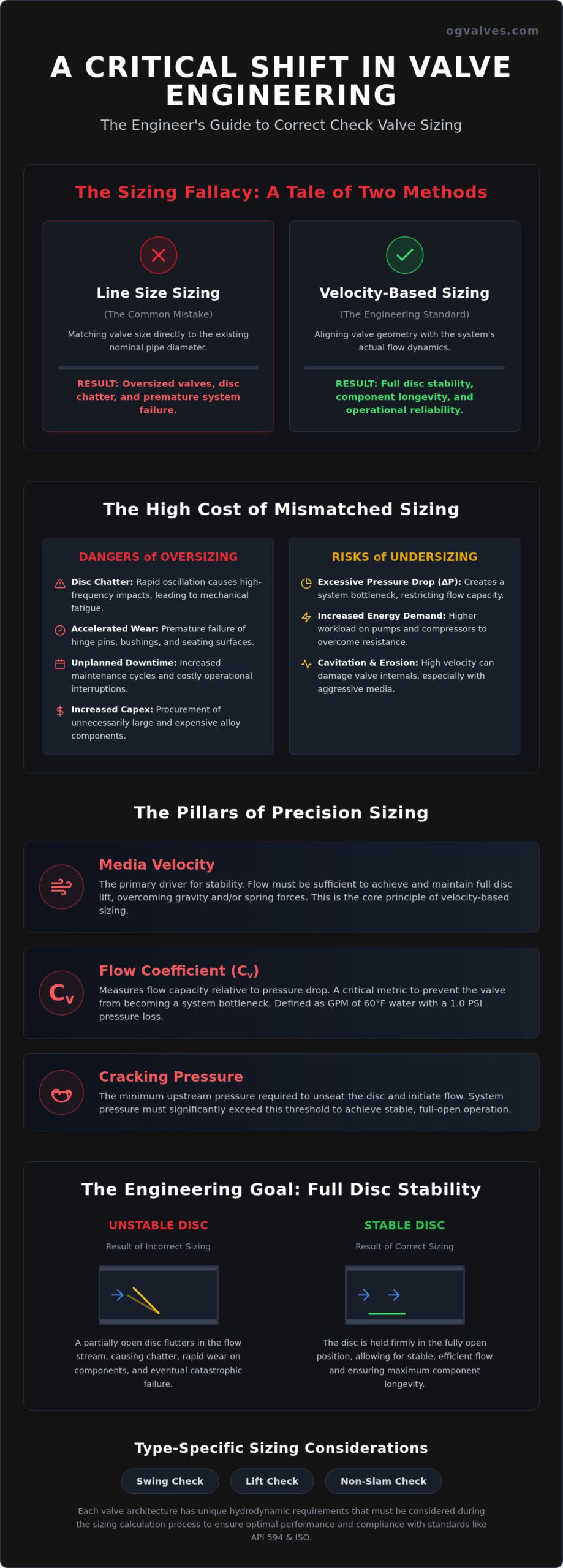
Sizing a check valve based solely on the upstream pipe diameter is a technical error that leads to systemic failure. While it’s common practice to match valve size to existing piping, this approach often results in oversized components that fail to reach full disc lift during standard operations. This comprehensive check valve sizing guide provides the engineering framework necessary to ensure disc stability and prevent the premature wear caused by disc chatter. It’s a clinical shift from nominal pipe sizing to velocity-based selection, prioritizing the mechanical integrity of the flow control system.
You recognize that excessive pressure drop and water hammer aren’t just maintenance nuisances; they’re direct threats to structural integrity and operational uptime. By calculating for minimum flow requirements rather than maximum capacity, engineers can ensure compliance with API 594 and ISO standards while minimizing energy loss. This guide details the technical parameters required to achieve full disc stability, examining the critical relationship between flow coefficients, media density, and component longevity. We’ll provide the data-driven methodology needed to eliminate the root causes of valve failure in high-stakes industrial environments.
Key Takeaways
- Understand why sizing valves based on nominal pipe diameter leads to premature failure and how to transition to velocity-based selection.
- Master the technical application of Flow Coefficient (Cv) and cracking pressure to ensure full disc lift during minimum flow conditions.
- Utilize this check valve sizing guide to implement a rigorous engineering framework for calculating media properties and flow dynamics.
- Identify specific sizing nuances for Swing, Lift, and Non-Slam architectures to optimize performance in high-pressure industrial systems.
- Ensure component integrity by aligning sizing data with precise material specifications and Positive Material Identification (PMI) standards.
The Critical Distinction: Why Line Size Sizing Leads to Check Valve Failure
Check valve sizing is the systematic process of aligning a valve’s internal geometry and mechanical resistance with the actual hydrodynamic conditions of a piping system. It’s a departure from the common but flawed practice of selecting valves based on nominal pipe size (NPS). When a valve is chosen solely to match pipe diameter, the resulting installation often fails to account for the actual flow velocity required to hold the disc in a stable, fully open position. This discrepancy is the primary driver of premature mechanical failure in high-pressure industrial applications.
The fallacy of line-size selection is prevalent in legacy engineering specifications. Installing a valve based on pipe diameter frequently leads to unstable flow because industrial systems are often designed with future capacity in mind, resulting in oversized piping for current flow rates. Various Check valve designs require specific minimum velocities to overcome the gravitational or spring-loaded forces acting on the disc. If the media velocity is insufficient, the disc remains in a partially open state, susceptible to the turbulent forces of the fluid.
This instability manifests as disc chatter. The disc oscillates rapidly, striking the seat or internal stops with high frequency. This kinetic energy transfer causes accelerated wear on hinge pins, bushings, and seating surfaces. Achieving a constant flow velocity above the minimum required for full disc lift is the primary defense against mechanical fatigue and catastrophic component failure.
The Cost of Oversizing in Heavy Industry
Oversizing increases initial capital expenditure through the procurement of larger, more expensive alloy components. Beyond the purchase price, the operational risks are severe. Oversized valves fail to achieve full lift, creating a restricted flow path that induces turbulence and erratic pressure fluctuations. This instability shortens maintenance cycles and leads to unplanned facility downtime, as technicians must replace prematurely worn internals. Precision is mandatory to avoid these unnecessary lifecycle costs.
Undersizing and Pressure Drop Limitations
Undersizing presents a different set of technical challenges. While an undersized valve ensures disc stability, it introduces excessive pressure drop (ΔP), which increases the energy demand on pumps and compressors. In high-velocity systems, undersizing elevates the risk of cavitation and localized erosion, particularly in aggressive media. A comprehensive check valve sizing guide balances these factors to ensure the valve provides sufficient flow capacity while maintaining system safety and efficiency. Engineers must verify that the selected valve doesn’t compromise the pressure-temperature ratings established by ASME B16.34.
Technical precision in an industrial check valve sizing guide requires an analysis of fluid dynamics that goes beyond simple flow rates. The Flow Coefficient (Cv) is the standard metric used to determine flow capacity relative to a specific pressure drop. It defines the volume of 60°F water, in gallons per minute, that flows through the valve with a pressure loss of 1.0 psi. For engineers, Cv is the baseline for ensuring the valve doesn’t become a bottleneck in high-capacity systems.
Cracking pressure is the minimum upstream differential pressure required to unseat the disc and initiate flow, a value that dictates the initial opening percentage and subsequent flow profile. If the system pressure doesn’t significantly exceed this threshold, the valve won’t achieve the necessary lift for stable operation. This parameter is particularly critical in low-pressure systems where the weight of the disc or the resistance of a spring can impede flow. Media density and viscosity also play fundamental roles; sizing for compressible gases requires different mathematical models than those used for incompressible liquids to account for density changes and potential sonic velocity limits.
Calculating Flow Velocity for Disc Stability
Determining the velocity required for full disc lift is essential to prevent the mechanical issues discussed in previous sections. Each valve architecture has a unique threshold where the hydrodynamic force of the media balances the mechanical resistance of the disc assembly. Engineering standards provide the formulas to calculate the minimum velocity for disc stability based on valve geometry and media properties. Spring rates also impact this calculation; higher spring tensions require more upstream pressure to maintain a fully open position. Turbulence near the valve inlet can cause erratic disc behavior, making it necessary to account for upstream piping configurations during the sizing process.
Viscosity and Temperature Corrections
High-viscosity fluids, common in petrochemical applications, increase frictional resistance and necessitate adjustments to the standard Cv calculations. As viscosity increases, the Reynolds number decreases, potentially shifting the flow from turbulent to laminar regimes. In power generation, high-temperature operations require consideration of thermal expansion in both the valve body and the internal trim. These temperature shifts also alter the specific gravity of the media, which directly affects the pressure drop across the valve. Consulting the technical specifications for high-performance check valves ensures that the selected component maintains its pressure-temperature rating across all operational modes. Using standardized reference values for industrial media provides a consistent baseline for these complex calculations.
Type-Specific Sizing Considerations: Swing, Lift, and Non-Slam Architectures
Industrial valve selection requires an exact match between the mechanical architecture and the system’s operational profile. Swing check valves are sized based on their ability to maintain a fully open disc in both horizontal and vertical orientations. In vertical up-flow installations, the media velocity must overcome both the disc weight and gravitational force, necessitating a higher minimum flow than horizontal configurations. Conversely, lift check valves are engineered for high-pressure performance but are restricted by their internal geometry, which often requires vertical alignment to ensure reliable seating. For a deeper technical analysis of these configurations, consult our resource on Understanding Industrial Check Valves: Design, Function, and Critical Selection (2026).
Dual plate and nozzle architectures represent the primary defense against water hammer in critical infrastructure. This check valve sizing guide emphasizes that nozzle (axial) valves are sized specifically for rapid closure, utilizing a short stroke and spring assistance to close before the fluid column reverses direction. This mechanical response prevents the kinetic energy of the reversing fluid from slamming the disc against the seat. It prevents water hammer. Such precision is essential in high-stakes environments like power generation and petrochemical processing where the cost of failure is absolute.
Sizing for Non-Slam Performance
Non-slam performance is a function of disc mass and the deceleration rate of the fluid column. In high-velocity pump discharge lines, the fluid column decelerates rapidly when the pump stops. Sizing must ensure the disc’s inertia is low enough, and the spring force high enough, to complete closure within milliseconds of zero flow. This calculation prevents pressure spikes, protecting sensitive downstream instrumentation and ensuring adherence to API 6D standards. Precision is mandatory.
Dual Plate and Tilting Disc Nuances
Dual plate designs offer space-saving advantages in large-diameter piping but introduce specific flow restriction trade-offs. Sizing requires an evaluation of the pressure drop across the central hinge pin and plates. For systems with low-pressure drop requirements, tilting disc valves provide superior hydrodynamic profiles while maintaining sealing integrity. Correct sizing ensures these valves don’t oscillate during low-flow periods, which is critical for maintaining long-term seat reliability and avoiding unplanned downtime.
Calculating Minimum Flow for Disc Stability: A Step-by-Step Engineering Framework
Precision at the procurement stage is non-negotiable. Heavy industrial infrastructure requires technical accuracy from the outset, as field-based resizing is often impractical and costly. This check valve sizing guide utilizes a five-step engineering framework to ensure operational stability and prevent the mechanical fatigue associated with improper selection.
- Step 1: Define the maximum and minimum system flow rates across all operational modes, including startup, shutdown, and emergency bypass conditions.
- Step 2: Determine media properties, specifically Specific Gravity (SG), Viscosity, and Vapour Pressure at peak operating temperatures.
- Step 3: Calculate the required Flow Coefficient (Cv) for the maximum flow condition to ensure the valve doesn’t exceed the allowable pressure drop.
- Step 4: Verify that the minimum flow velocity exceeds the manufacturer’s specified ‘Full Lift’ velocity. This ensures the disc remains stable against the stop, preventing the chatter described in previous sections.
- Step 5: Validate material compatibility with the calculated flow velocity. High-velocity media can cause localized erosion if the valve trim materials aren’t sufficiently hardened or selected for the specific chemical profile.
Verification of API and ISO Standards
Sizing results must align with global regulatory benchmarks to ensure safety and interchangeability. This includes adherence to API 594 for wafer and lug designs or API 6D for pipeline applications. For a detailed breakdown of these benchmarks, refer to Industrial Valves: The Engineer’s Comprehensive Guide to Selection and Standards (2026). Validating pressure-temperature ratings against ASME B16.34 is also essential to ensure the valve body maintains structural integrity under peak operational stresses. Failure to meet these standards can lead to regulatory non-compliance and increased liability in critical infrastructure projects.
Addressing Cavitation and Flashing
Cavitation occurs when the local pressure drop across the valve internals causes the media pressure to fall below its vapour pressure. This results in the formation and subsequent violent collapse of vapour bubbles, causing severe pitting and vibration. Sizing adjustments, such as selecting a valve with a different flow profile or modifying the upstream pressure, can mitigate these effects. Predicting component lifespan involves calculating the cavitation index based on the ratio of pressure drop to the difference between inlet and vapour pressure. If your system parameters suggest volatile media behavior, consult with our technical specialists to verify your component selection and ensure long-term durability.
Procurement Excellence: Selecting High-Specification Check Valves for Critical Infrastructure
Transitioning from mathematical calculation to physical procurement requires a clinical approach to material science. The data generated by a rigorous check valve sizing guide serves as the technical foundation for specifying metallurgy capable of withstanding calculated flow dynamics. While carbon steel remains the standard for many hydrocarbon services, high-velocity or corrosive environments necessitate the use of stainless steel or super duplex alloys to prevent localized erosion and chemical degradation. Precision in material selection is as vital as the dimensional accuracy of the valve’s internal geometry.
Verification is the final stage of the sizing and procurement workflow. Positive Material Identification (PMI) testing ensures that the delivered component matches the project’s metallurgical requirements, eliminating the risk of material non-compliance in complex global supply chains. Technical partners must validate these selections against project-specific P&IDs to confirm that the valve’s Cv and cracking pressure align with the broader system architecture. This meticulous alignment prevents the mechanical failures associated with mismatched components in high-stakes infrastructure.
Material Integrity and Technical Support
Material selection is as critical as dimensional sizing in ensuring long-term seat reliability and system safety. In power generation, where thermal cycling and high-pressure steam are standard, the interaction between flow velocity and alloy hardness determines the component’s functional lifespan. Utilizing technical expertise to resolve complex sizing dilemmas ensures that the valve survives the operational environment. For insights into adjacent flow control components, see our A Technical Guide to Industrial Gate Valves: Design, Standards, and Selection (2026). Professional consultation bridge the gap between theoretical sizing and practical durability.
Ensuring Minimal Downtime with Global Supply
Inventory availability is the cornerstone of operational resilience in heavy industry. When a check valve fails due to improper legacy sizing or unexpected process shifts, the cost of downtime in the petrochemical sector can be catastrophic. Fast-track delivery of sized-to-order industrial components is essential for urgent maintenance and facility turnarounds. A technical partner with an established global supply chain ensures that high-specification valves reach the site without the delays typical of custom manufacturing cycles. This logistical capability allows procurement specialists to focus on quality assurance rather than lead-time management.
Contact OG VALVES for technical support and high-specification valve procurement.
Optimizing System Longevity Through Precision Flow Control
Precision in check valve selection is the primary defense against mechanical fatigue and operational downtime in critical infrastructure. As established throughout this check valve sizing guide, engineers must prioritize hydrodynamic stability over nominal pipe diameter to prevent the catastrophic effects of disc chatter and water hammer. Validating these technical calculations against API and ISO standards ensures that every component maintains structural integrity under the rigorous demands of the oil, gas, and power generation sectors. Correct sizing is a clinical necessity rather than a mere recommendation.
OG VALVES LTD. operates as a specialized technical partner, providing high-specification components that meet the exact requirements of heavy industry. Our global fast-track delivery capabilities and expertise in industrial specifications allow procurement teams to secure reliable flow control solutions without compromising on lead times. By aligning sizing data with rigorous material validation and quality control, you ensure the long-term reliability of your piping systems. Request a technical quote for high-specification industrial check valves from OG VALVES to begin the validation process. Achieving full disc stability safeguards your facility’s operational output and structural safety.
Frequently Asked Questions
How do I calculate the minimum flow required for a check valve?
Calculate the velocity needed to achieve full disc lift by using manufacturer-specific formulas that account for disc weight, arm length, and media properties like specific gravity. Ensuring the minimum operational flow exceeds this threshold prevents the disc from oscillating against the seat. This calculation is a core component of any professional check valve sizing guide to ensure long-term mechanical reliability and system stability.
Can a check valve be larger than the pipe size?
While technically possible, installing a valve larger than the pipe diameter is discouraged in industrial flow control. This configuration reduces the media velocity within the valve body, often preventing the disc from reaching a stable, fully open position. Such a mismatch typically results in accelerated wear on internal components and increased turbulence. Standard practice involves selecting a valve that matches or is smaller than the line size.
What happens if a check valve is oversized for the application?
Oversized valves suffer from disc chatter because the flow velocity is insufficient to hold the disc against the internal stops. This constant oscillation causes severe mechanical fatigue on hinge pins and seating surfaces, leading to premature failure. Additionally, oversized valves fail to provide a stable flow profile, which can introduce turbulence into downstream equipment. Precise sizing ensures the disc remains stationary under normal operating conditions.
How does cracking pressure affect check valve sizing?
Cracking pressure defines the minimum upstream differential pressure required to initiate flow and move the disc from the seat. In a check valve sizing guide, this parameter is critical for low-pressure systems where the valve must open fully without creating excessive backpressure. If the system’s operational pressure is too close to the cracking pressure, the valve may only partially open, causing flow restriction and potential instability.
What is the difference between Cv and Kv in valve sizing?
Cv and Kv are both flow coefficients used to describe a valve’s capacity, differing primarily in their units of measurement. Cv represents the flow of 60°F water in US gallons per minute with a 1.0 psi pressure drop. Kv measures the flow of water between 5°C and 40°C in cubic meters per hour with a 1.0 bar pressure drop. Engineers use the conversion factor Cv = 1.156 x Kv to align international specifications.
Is it necessary to size check valves differently for vertical flow?
Yes, vertical up-flow orientations require higher velocities to overcome the additional gravitational force acting on the disc. When sizing for vertical lines, the minimum flow velocity must be calculated to account for both the mechanical resistance of the valve and the weight of the media column. Failure to adjust for orientation can result in the disc failing to reach full lift, leading to increased pressure drop and component wear.
How do I prevent water hammer through proper check valve sizing?
Preventing water hammer requires selecting a valve sized for rapid closure before the fluid column reverses direction. Non-slam or nozzle check valves are often sized with shorter strokes and spring assistance to ensure the disc seats at the moment of zero flow. This proactive closure prevents the kinetic energy of the reversing fluid from slamming the disc, protecting the piping from structural damage and pressure surges.
What industrial standards govern check valve sizing and testing?
Industrial check valves are governed by API 594 for wafer and lug designs and API 6D for pipeline applications. These standards define the pressure-temperature ratings, material requirements, and leakage testing protocols necessary for high-stakes environments. Additionally, ASME B16.34 provides the framework for valve body dimensions and pressure containment. Adherence to these global benchmarks ensures that the sized components meet the safety requirements of the oil and gas sectors.
 Responsive Menu