Factory Acceptance Test (FAT) Procedure for Valves: A Technical Engineering Guide
April 25, 2026
Home+Factory Acceptance Test (FAT) Procedure for Valves: A Technical Engineering Guide
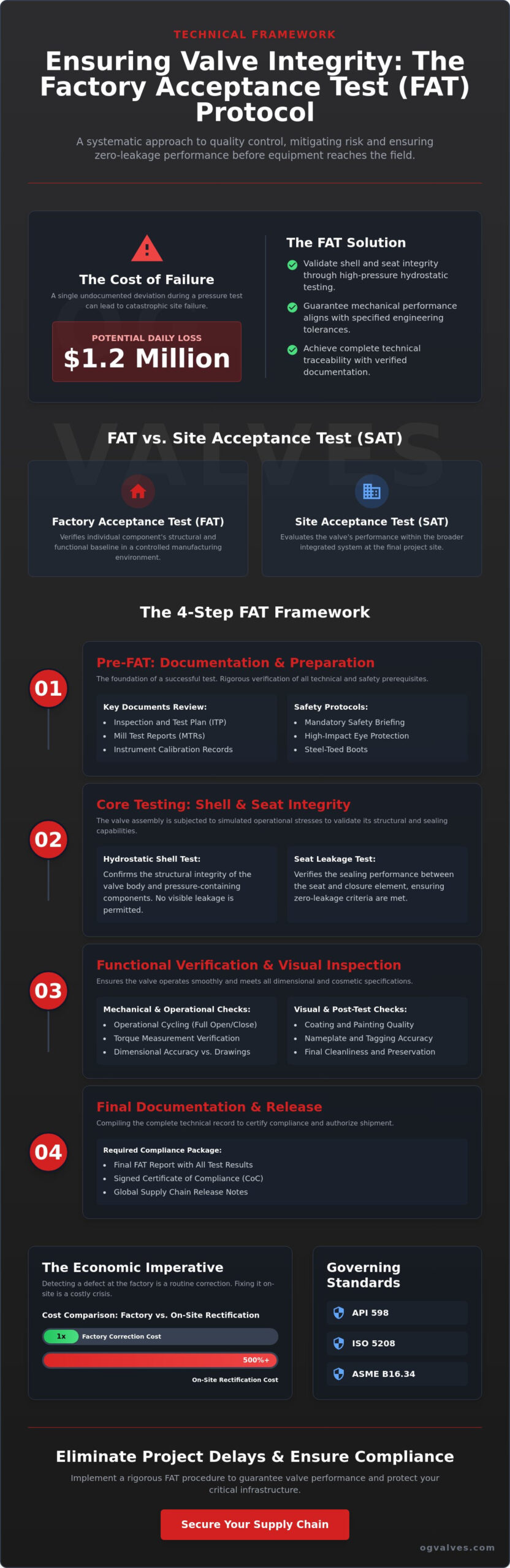
A single undocumented deviation during a pressure test can result in a 1.2 million dollar daily operational loss in high-pressure offshore environments. Engineers understand that technical ambiguity during the final manufacturing stage is the primary driver of catastrophic site failure. You recognize that adherence to API 598 or ISO 5208 isn’t just a regulatory hurdle; it’s a critical safeguard for industrial integrity. Implementing a standardized factory acceptance test procedure for valves is the only way to mitigate these risks before equipment reaches the field.
This guide provides a comprehensive technical framework for executing rigorous factory acceptance tests to ensure valve integrity, compliance, and operational safety. We’ll examine the specific parameters for hydrostatic shell testing, seat leakage criteria, and the documentation required for complete technical traceability. By following this clinical approach to quality control, you’ll achieve verified zero-leakage performance and eliminate the project delays associated with improper documentation. Every technical detail matters when the safety of critical infrastructure is at stake.
Key Takeaways
Establish a rigorous technical framework for verifying the Inspection and Test Plan (ITP) and instrument calibration to ensure precision during the pre-FAT phase.
Execute a standardized factory acceptance test procedure for valves to validate shell and seat integrity through high-pressure hydrostatic testing in accordance with international safety standards.
Perform precise functional verification, including operational cycling and torque measurement, to guarantee that mechanical performance aligns with specified engineering tolerances.
Secure project compliance by mastering the documentation requirements for the final FAT report, Certificate of Compliance (CoC), and global supply chain release notes.
Defining the Factory Acceptance Test (FAT) for Industrial Valves
The factory acceptance test procedure for valves constitutes the definitive quality control stage within the manufacturing lifecycle. This process serves as the final technical gatekeeper, ensuring that every flow control component adheres to specified engineering parameters before it leaves the production facility. Unlike generic mill tests that only validate raw material chemistry or mechanical properties of the steel, a comprehensive FAT evaluates the fully assembled unit under simulated operational stresses. It’s a critical component of Acceptance testing protocols designed to confirm that the equipment meets the rigorous purchase order requirements and engineering specifications of the energy and water sectors.
Engineers distinguish the FAT from Site Acceptance Testing (SAT) by its controlled environment and specific focus. While the SAT evaluates the valve’s performance within the broader integrated system at the project site, the FAT focuses on the individual component’s structural and functional baseline. Implementing a standardized factory acceptance test procedure for valves allows for the identification of manufacturing deviations before global logistics costs are incurred. The procedure verifies three primary categories: dimensional accuracy against technical drawings, structural integrity through high-pressure shell testing, and functional performance of the actuator and seating mechanisms.
Regulatory Framework and Global Standards
Standardization is essential for maintaining industrial safety and interchangeability. The API 598 standard remains the primary benchmark for valve inspection and testing, specifying the required duration and pressure levels for shell and seat tests. Compliance with ISO 5208 and ASME B16.34 provides additional layers of technical assurance, particularly regarding pressure-temperature ratings and permissible leakage rates. A project-specific Quality Assurance Plan (QAP) often dictates the precise scope of these tests, incorporating unique client requirements that exceed base international standards to account for specific service conditions like high-cycle or abrasive media.
The Economic and Safety Imperative
The economic justification for a rigorous FAT is absolute. Detecting a seat leak or a casting defect at the factory is a routine correction; identifying the same failure after the valve is welded into a subsea manifold or a high-pressure refinery line can increase rectification costs by 500% or more. Beyond financial risk, FAT procedures include fugitive emission testing to ensure environmental compliance with local and international regulations. Witnessed testing protocols, where a third-party inspector or client representative observes the procedure, establish the necessary technical trust for critical infrastructure projects. This systematic approach ensures that only valves with documented performance integrity reach the installation phase.
Pre-FAT Requirements: Documentation and Preparation
Success in any factory acceptance test procedure for valves relies on the rigor of the preliminary phase. Before the physical application of pressure, the manufacturer must present a comprehensive documentation package for review. The primary document is the Inspection and Test Plan (ITP), which outlines every verification step, witness point, and acceptance criteria. It’s a common cause of project delays when an ITP lacks the engineering firm’s approval stamp. Material traceability is equally critical. Verification of Mill Test Reports (MTRs) ensures that pressure-containing components, such as forged steel bodies or duplex stainless steel stems, meet the chemical and mechanical requirements defined in the procurement specification. Every heat number on the physical valve must correlate exactly with the provided documentation to maintain the integrity of the supply chain.
Safety protocols are non-negotiable during high-pressure testing. All personnel, including third-party witness inspectors, must attend a safety briefing covering emergency shutdown procedures and designated safe zones. Required Personal Protective Equipment (PPE) includes high-impact eye protection, steel-toed boots, and hearing protection for gas-based testing. These measures align with the API 598 valve testing standard, which dictates the environmental and procedural safety controls necessary for high-pressure shell and seat leakage examinations. If the facility’s safety standards don’t meet these international benchmarks, the FAT cannot proceed.
Calibration and Instrument Integrity
Testing accuracy depends on the precision of the measurement tools. All pressure gauges must demonstrate an accuracy within +/- 1 percent of the full-scale range. Calibration certificates for gauges, torque sensors, and thermometers must be valid, typically dated within the previous 12 months. For critical service valves, digital chart recorders provide the necessary duration logging to prove pressure stability over the required hold times. If the procedure involves gas testing, the sensitivity of electronic leak detectors or bubble-forming fluids must be verified against ISO 5208 standards to ensure even minute leaks are identified. You can review our quality assurance protocols to see how we maintain these instrument standards for every project.
Document Review and Preliminary Checks
The inspector performs a physical-to-drawing correlation before the test bench is energized. This involves checking the General Arrangement (GA) drawings against the physical valve dimensions, flange ratings, and face-to-face lengths. The Bill of Materials (BOM) is cross-referenced to ensure internal trim materials match the technical data sheet. Finally, the manufacturer must provide Non-Destructive Examination (NDE) reports. These include Radiography (RT) for cast components or Dye Penetrant (PT) for weld overlays. Verifying these reports ensures that no subsurface defects exist that could lead to catastrophic failure during the pressure cycle. It’s a vital step in the factory acceptance test procedure for valves that prevents the testing of compromised hardware.
The Core Pressure Testing Protocol: Shell and Seat Integrity
The factory acceptance test procedure for valves centers on the validation of pressure-containing boundaries. This phase ensures the assembly withstands operational stresses without catastrophic failure or environmental release. Technical staff must execute the High-Pressure Hydrostatic Shell Test by applying a test pressure typically 1.5 times the Cold Working Pressure (CWP) at 100°F. This rigorous benchmark identifies casting or forging defects that aren’t visible under nominal conditions.
During the shell test, the valve remains partially open to ensure the entire body cavity and bonnet area are pressurized. Inspection teams look for “sweating” or visible droplets through the metal body. Retention times vary by valve size; for instance, a 2-inch valve usually requires a 15-second hold, while valves over 10 inches require at least 300 seconds to ensure stabilization. These durations are strictly governed by API 598 or ASME B16.34 standards to ensure data repeatability.
Hydrostatic Shell Testing Procedures
Engineers calculate test pressures based on the specific material grade and pressure class. The medium is usually water containing corrosion inhibitors to prevent internal oxidation. For check valves, technicians must observe back-pressure limits to avoid damaging internal hinges or discs during reverse flow testing. When the valve is intended for gas service, pneumatic testing with air or nitrogen at 1.1 times the CWP is often required. This provides a more sensitive detection of micro-porosity in the casting compared to liquid mediums.
Seat Leakage and Closure Verification
Seat integrity testing determines the valve’s ability to provide a bubble-tight shutoff. API 598 defines allowable leakage rates, distinguishing between “Zero Leakage” (Rate A) for resilient-seated valves and specific drop counts for metal-seated variants. For gate valves, the protocol requires testing both sides of the wedge to verify bidirectional sealing capability. This is vital for isolation safety in high-pressure pipelines.
Low-pressure seat tests use air or nitrogen at 60 to 100 psi to detect leaks that high-pressure water might bridge due to surface tension. Conversely, high-pressure seat tests verify the mechanical strength of the closure members under maximum service conditions. Backseat testing is mandatory for globe and gate valve designs. It confirms that the stem-to-bonnet seal functions correctly when the valve is fully open. This allows for packing adjustments under pressure without risking a blow-out. Every result is documented in the final quality certification to verify that the factory acceptance test procedure for valves met all project specifications.
Functional Verification and Visual Inspection Procedures
Operational cycling constitutes the primary phase of functional verification. Each unit undergoes a minimum of five complete cycles from full open to full close to confirm smooth travel and the absence of mechanical interference. Engineers measure breakaway torque, the force required to initiate movement, and running torque, the force required to maintain it. These values must align with the torque signatures defined in the technical specification. If torque exceeds 10% of the calculated design limit, the unit fails the factory acceptance test procedure for valves. This data is recorded to establish a performance baseline for future field maintenance.
Dimensional verification requires calibrated vernier calipers and ultrasonic thickness gauges. Technicians compare the physical unit against approved General Arrangement (GA) drawings. Critical measurements include end-to-end dimensions, flange thickness, and bolt hole alignment. A deviation of 1.5mm in face-to-face length can compromise pipeline integrity during installation. Precise adherence to ASME B16.10 standards ensures that the valve integrates seamlessly into the existing piping infrastructure without inducing stress on flange connections.
Automated Valve Assembly Testing
Integration of valve actuators into the FAT cycle is mandatory for automated packages. This phase verifies limit switch settings to ensure precise signal feedback at 0% and 100% travel. Fail-safe positions, whether Open, Closed, or Last, are tested by simulating a loss of power or pneumatic supply. For emergency shutdown (ESD) valves, stroke time testing is critical. The valve must reach its safe position within the specified time, often less than 1 second per inch of pipe diameter, to prevent catastrophic system overpressure in high-flow environments.
Visual and Cosmetic Standards
Visual inspection targets surface integrity and identification accuracy. Inspectors examine the valve body for casting defects like porosity or sand inclusions using MSS SP-55 standards as a benchmark. Every nameplate must display clear, indelible data, including heat numbers, pressure class, and material grades. Coating integrity is verified through Dry Film Thickness (DFT) measurements and spark testing. A standard three-layer epoxy coating typically requires a minimum thickness of 250 to 300 microns to ensure long-term corrosion resistance in harsh offshore environments. Any evidence of mechanical damage or burrs on sealing surfaces results in immediate rejection until remediation is performed.
Verify your project specifications by contacting our engineering team to review compliance documentation for critical service valves.
Final Documentation, Release, and Compliance
The conclusion of the factory acceptance test procedure for valves marks the transition from physical verification to formal certification. This phase ensures that the valve assembly meets every contractual specification and international standard before leaving the facility. A Release Note acts as the final gatekeeper in the global supply chain, confirming that the Third Party Inspector and the manufacturer have verified all test results. Without this document, international logistics cannot proceed; it serves as the definitive proof of technical acceptance for project stakeholders. The Certificate of Compliance (CoC) follows, providing a legal guarantee that the materials and performance meet the purchase order requirements.
The FAT Report Structure
Post-Test Preservation and Logistics
Post-test handling is critical to maintaining the mechanical integrity of the unit. After hydrotesting, technicians must thoroughly dry the internal cavities to prevent microbial corrosion or oxidation. Specialized corrosion inhibitors are applied to the internal surfaces and machined faces. Flange faces are protected with heavy-duty plastic or metallic blanking plates to prevent mechanical damage during transit. For international projects, OG Valves utilizes ISPM 15 compliant heat-treated timber crates, ensuring the equipment survives the rigors of sea or air freight.
A final checklist before the valve leaves the facility includes:
Verification of stainless steel tagging and serial numbers against the packing list.
Confirmation that all blanking plugs and thread protectors are securely installed.
Verification of paint thickness and coating integrity per the project specification.
Inclusion of the signed inspection release note in the shipping documentation.
Technical compliance management at OG Valves ensures that standards are maintained across complex global jurisdictions. By adhering to a rigorous factory acceptance test procedure for valves, the company provides engineering teams with the certainty that every unit will perform as specified in high-pressure oil, gas, and water treatment environments. This methodical approach to documentation and preservation minimizes the risk of site-arrival damage and ensures immediate readiness for installation in critical infrastructure.
Ensuring Long-Term Operational Integrity through Rigorous Verification
Adhering to a rigorous factory acceptance test procedure for valves is essential for ensuring long-term operational integrity in high-pressure environments. By strictly following API 598 and ISO 5208 standards, engineers verify that every component meets specified shell and seat leakage tolerances before site delivery. This methodical verification process, supported by complete material test reports and detailed inspection test plans, effectively mitigates risk in critical oil and gas infrastructure. It’s a proven method for eliminating field failures before they occur. OG Valves maintains an extensive inventory of API 6D and ISO 9001 certified components to support immediate project requirements. We provide comprehensive technical support and compliance auditing for every order; this ensures that high-specification equipment aligns with international safety mandates. Our logistics network facilitates global fast-track delivery for urgent infrastructure repairs. Precision engineering and documented compliance form the foundation of a safe industrial facility. Securing verified components today protects the operational lifespan of your entire system.
What is the standard duration for a valve hydrostatic shell test?
The duration for a valve hydrostatic shell test is determined by the nominal pipe size (NPS) and pressure class as defined in API 598. For valves with an NPS of 2 or smaller, the minimum test duration is 15 seconds. Larger units, specifically those between NPS 2.5 and NPS 6, require a minimum hold time of 60 seconds to ensure pressure boundary integrity. These durations represent the minimum period for visual inspection of external surfaces for leakage.
Can a factory acceptance test be conducted virtually via video link?
Virtual factory acceptance tests are conducted via high-definition video links and real-time data streaming. This practice became standard in 2020 to maintain project timelines during travel restrictions. Remote inspectors verify gauge readings and valve operation through multi-angle camera setups. While effective, the protocol must be detailed in the Quality Assurance Plan (QAP) to ensure all verification points meet the project’s technical specifications and safety standards.
What happens if a valve fails the seat leakage test during FAT?
If a valve fails the seat leakage test during the factory acceptance test procedure for valves, it’s immediately rejected and quarantined. Technicians must conduct a root cause analysis to identify if the failure stems from seat damage, debris, or misalignment. Following corrective actions or component replacement, the valve undergoes a full retest of all FAT parameters. Repeat failures often necessitate a comprehensive review of the manufacturing process or material batch integrity.
How does API 598 differ from ISO 5208 in testing requirements?
API 598 and ISO 5208 differ primarily in their leakage rate classifications and test duration requirements. API 598 is the standard for refinery and petrochemical valves, often allowing zero visible leakage for resilient-seated valves. ISO 5208 utilizes a Rate A through Rate G scale to define permissible leakage based on the valve’s intended application. Engineers select the standard based on the specific pressure ratings and operational criticalities of the piping system.
Are third-party inspectors mandatory for a valve FAT?
Third-party inspectors aren’t mandatory under ASME or API codes, but 85% of high-pressure oil and gas contracts require them. Their presence provides an independent verification layer that ensures the manufacturer adheres strictly to the approved Inspection and Test Plan (ITP). For critical service valves, such as those in subsea or cryogenic applications, third-party witness points are standard to mitigate the risk of catastrophic field failure and ensure full regulatory compliance.
What specific documentation is required before the FAT can commence?
Before the FAT commences, the manufacturer must provide a complete documentation package including the approved Inspection and Test Plan (ITP) and General Arrangement (GA) drawings. Material Test Reports (MTRs) for pressure-containing parts must be verified against ASME Section II requirements. Non-Destructive Testing (NDT) reports, such as radiography or dye penetrant results, must also be signed off to confirm the structural integrity of the valve castings or forgings.
Is a pneumatic test required for all industrial valves?
Pneumatic testing isn’t required for all industrial valves and is typically reserved for gas service or low-pressure applications. API 598 specifies it as an optional high-pressure test or a mandatory low-pressure closure test for certain valve types. Because compressed air stores 200 times more energy than water at the same pressure, pneumatic tests require specialized safety bunkers and rigorous risk assessments to protect personnel from potential explosive decompression.
How is torque measured during the functional test of a manual valve?
During the functional test of a manual valve, torque is measured using a calibrated torque wrench or a specialized load cell mounted on the stem. This measurement ensures the valve operates within the maximum allowable stem torque (MAST) limits. Engineers record the break-to-open and running torque values to verify that the valve’s internal friction and seating forces align with the design specifications. Accurate torque data is vital for ensuring long-term operational reliability.
 Responsive Menu