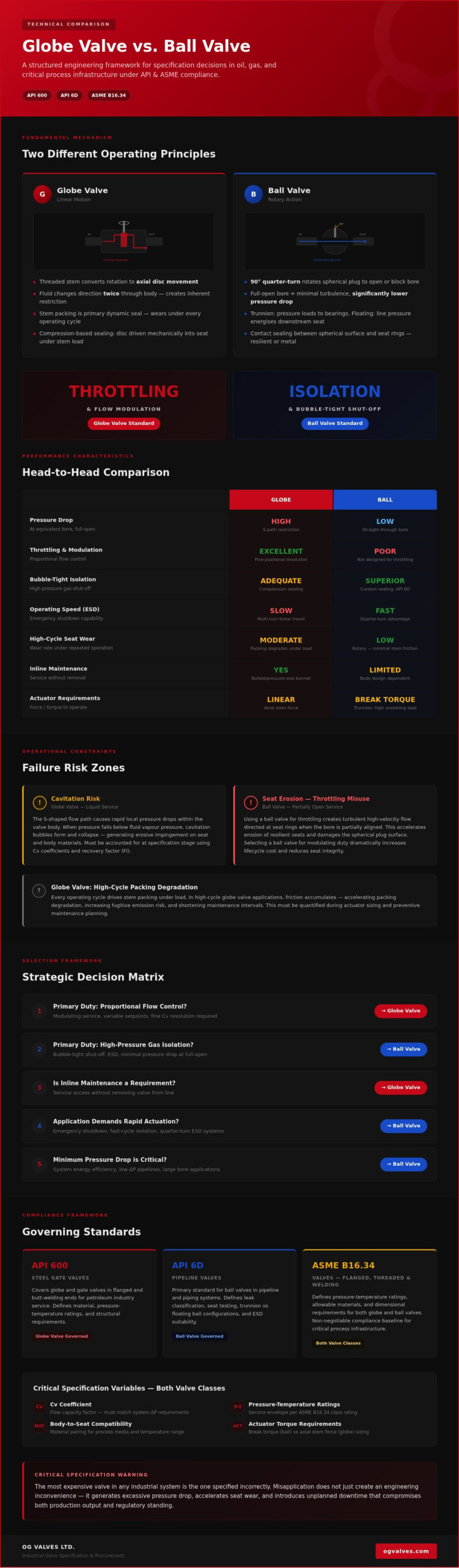
The most expensive valve in any industrial system is the one specified incorrectly. In the globe valve vs ball valve debate, the wrong choice doesn’t just create an engineering inconvenience; it generates excessive pressure drop, accelerates seat wear, and introduces the kind of unplanned downtime that compromises both production output and regulatory standing. For procurement specialists and process engineers operating under API and ASME compliance frameworks, this is not a theoretical risk.
The instinct to treat valve selection as a binary choice between throttling and isolation is understandable. It’s a reasonable starting point. But it omits the variables that determine long-term system performance: Cv coefficients, actuator torque requirements, body-to-seat material compatibility, and the specific pressure-temperature ratings that define acceptable service envelopes under API 600 and API 6D.
This analysis moves beyond general application guidance. It delivers a structured, technical comparison of globe and ball valve architectures, covering flow characteristics, seat integrity under cyclic service, pressure drop behaviour, and the regulatory standards governing each valve class. The objective is a specification framework that engineers can apply directly to high-stakes procurement decisions.
Key Takeaways
- The globe valve vs ball valve decision is governed by mechanical architecture: linear stem movement and an S-shaped flow path versus 90-degree rotary action and a straight-through bore, with each design producing fundamentally different pressure drop and flow control outcomes.
- Globe valves are the engineering standard for throttling and modulating service, while ball valves deliver superior bubble-tight shut-off in high-pressure gas isolation applications — selecting the wrong type for the duty cycle accelerates seat wear and increases lifecycle cost.
- Cavitation and high inherent pressure drop are quantifiable operational risks in globe valve installations; this article identifies the specific process conditions under which these failure modes are triggered and how to account for them at the specification stage.
- API 600, API 6D, and ASME B16.34 define the compliance boundaries for each valve class — understanding which standard governs your application is a non-negotiable prerequisite for procurement in oil, gas, and critical process infrastructure.
- A structured decision matrix covering flow control priority, pressure recovery requirements, and inline maintenance capability provides a direct framework for resolving high-stakes valve selection without ambiguity.
Fundamental Mechanisms: Linear Globe vs. Rotary Ball Design
The mechanical distinction between globe and ball valves isn’t a matter of degree; it’s a difference in fundamental operating principle. One converts rotational input into linear disc travel. The other rotates a spherical plug through 90 degrees to align or block a bore. These two mechanisms produce entirely different flow characteristics, sealing behaviours, and actuator requirements, and understanding them at the component level is the prerequisite for any credible globe valve vs ball valve specification decision.
The Globe Valve: Precision Through Linear Motion
Globe valve operation is governed by the vertical displacement of a disc or plug against a machined seat ring. As the threaded stem rotates, it translates that rotational input into axial movement, advancing or retracting the disc across the seat face. This arrangement creates an S-shaped internal flow path, where the process fluid changes direction twice as it passes through the valve body. The geometry is inherently restrictive, which is why globe valves carry a higher pressure drop coefficient than equivalent-bore ball valves, but it’s also what enables proportional flow modulation with fine positional resolution.
The bonnet assembly is central to pressure containment in this design. Bolted or pressure-seal bonnets maintain structural integrity under high-pressure service conditions, while the packing gland around the stem provides the primary dynamic seal against fugitive emissions. It’s this stem-packing interface that introduces a wear consideration specific to linear motion: every operating cycle drives the packing against the stem under load, generating friction that accumulates over time. In high-cycle applications, this translates to accelerated packing degradation and increased maintenance frequency, a factor that must be quantified during actuator and maintenance interval planning.
The Ball Valve: Efficiency Through Rotary Action
Ball valve architecture centres on a precision-machined spherical plug with a through-bore aligned to the pipeline diameter. A 90-degree rotation either presents the bore to the flow path for full open conditions or presents the solid face of the sphere for shut-off. This straight-through bore geometry, when fully open, produces minimal turbulence and a pressure drop significantly lower than a globe valve in equivalent service.
The quarter-turn operating cycle is a structural advantage in emergency shutdown (ESD) and rapid isolation applications. Actuator sizing for ball valves in large-diameter lines must account for the break torque required to unseat the ball from its seat rings, particularly in trunnion-mounted designs where upstream pressure loads are transferred to the trunnion bearings rather than the seats. Floating ball designs, by contrast, rely on line pressure to energise the downstream seat, which limits their practical application in larger bore sizes where seat load forces become unmanageable.
The sealing mechanism in each design reflects this architectural split. Globe valves use compression-based sealing, where the disc is mechanically driven into the seat under stem load. Ball valves use contact sealing between the spherical plug surface and resilient or metal seat rings, with floating designs relying on differential pressure to maintain the downstream seat seal. Each principle carries distinct implications for seat material selection, leak classification under API 6D, and suitability for specific process media.
Mechanical architecture determines operational capability. The S-shaped flow path of a globe valve and the straight-through bore of a ball valve don’t just produce different pressure drop profiles; they define the boundaries of what each valve can reliably do in service. Specifying outside those boundaries is where seat erosion, cavitation, and premature failure begin.
Throttling Precision and Pressure Regulation
The flow coefficient (Cv) is a standardised measure of a valve’s capacity to pass fluid at a given pressure differential, and it’s the primary sizing variable that separates a globe valve from a ball valve in modulating service.
Globe valves carry a lower inherent Cv than equivalent-bore ball valves, but that restriction is precisely engineered. The disc geometry is the critical variable. A parabolic or contoured plug produces an approximately equal-percentage flow characteristic, where each increment of stem travel delivers a proportional percentage increase in flow rather than a linear one. This characteristic is well-matched to pressure control loops and flow regulation applications where rangeability across a wide operating band is required. A flat disc, by contrast, produces a more linear characteristic with reduced resolution at low-lift positions, making it less suitable for fine modulating duty.
High differential pressure across a partially open globe valve introduces two quantifiable risks that most application guides understate: cavitation and flashing. Cavitation occurs when localised static pressure at the vena contracta drops below the fluid’s vapour pressure, forming vapour bubbles that collapse violently as pressure recovers downstream. The implosion energy is sufficient to pit hardened trim surfaces and erode valve bodies over time. Flashing occurs when the downstream pressure remains below vapour pressure, producing a sustained two-phase flow condition. Both phenomena are functions of the pressure recovery factor (FL) and the inlet pressure-to-vapour pressure ratio, and both must be evaluated at the specification stage, not after installation.
Isolation Integrity and Quick-Closing Requirements
Ball valves deliver what globe valves structurally cannot: bubble-tight shut-off at high differential pressure with minimal actuator input and a 90-degree stroke. This makes them the primary isolation component in industrial valves systems where emergency shutdown (ESD) response time and leak classification under API 6D are non-negotiable requirements.
The failure mode that results from misapplying a ball valve to throttling service is well-documented: wire drawing. When a ball valve is held at a partially open position under high differential pressure, the high-velocity fluid jet cuts across the exposed seat ring and ball surface, eroding the sealing geometry progressively. Once that geometry is compromised, the valve cannot achieve the leak-tight classification it was specified for. The seat damage is typically irreversible without full trim replacement.
The gate valve vs ball valve comparison for pure isolation tasks follows a similar logic. Gate valves offer a straight-through bore with low pressure drop when fully open, but their multi-turn operation and susceptibility to seat damage under partial opening conditions make them unsuitable for frequent cycling. Ball valves, with quarter-turn actuation and robust seat contact geometry, are the preferred isolation solution where cycle frequency is high and response time is critical.
In any globe valve vs ball valve specification review, the operational duty cycle is the deciding variable. If the valve will modulate, a globe valve with appropriate trim geometry is the correct selection. If it will isolate, a ball valve rated to the correct API 6D seat leak class is the engineering standard. Applying either valve outside its design envelope creates a failure condition, not a compromise.
Procurement teams sourcing both valve types for comparative evaluation or parallel system supply can review available API-rated globe and ball valve inventory through OG Valves’ industrial valve supply capability.
Operational Constraints: Cavitation, Pressure Drop, and Seat Integrity
Mechanical architecture determines failure mode. The S-shaped flow path that gives a globe valve its throttling precision also creates the conditions for cavitation, accelerated seat wear, and measurable energy loss under sustained differential pressure. These aren’t theoretical concerns; they’re quantifiable operational risks that must be evaluated before a valve reaches the specification sheet.
Managing Pressure Drop and Energy Efficiency
The resistance inherent in a globe valve’s directional flow changes produces a pressure drop coefficient significantly higher than an equivalent-bore ball valve in fully open service. In high-frequency cycling applications, this head loss accumulates into a real pumping cost burden. Systems with multiple globe valves in series compound the effect: each valve adds resistance that the pump must overcome continuously, increasing energy consumption across the operational lifetime of the installation.
Where system efficiency is the governing constraint, the straight-through bore of an industrial ball valve is the technically correct selection. A full-bore ball valve in the open position presents negligible obstruction to flow, with pressure drop approaching that of an equivalent length of straight pipe. For isolation duties on high-throughput lines, the energy cost differential between globe and ball valve installations is a legitimate lifecycle cost variable that procurement specifications should quantify, not assume.
Cavitation Mitigation in High-Pressure Systems
Cavitation in globe valves is a function of three variables: inlet pressure, downstream pressure, and the fluid’s vapour pressure at operating temperature. When the pressure at the vena contracta drops below vapour pressure, bubble formation begins. The subsequent pressure recovery causes those bubbles to collapse against trim surfaces with sufficient force to pit hardened metal. The physical evidence is unmistakable: cratered plug faces, eroded seat rings, and a characteristic crackling noise during operation.
Anti-cavitation trim addresses this through staged pressure reduction. Rather than allowing a single large pressure drop across the seat, multi-stage trim geometries distribute the total pressure differential across a series of flow restrictions, keeping localised static pressure above vapour pressure at each stage. This approach extends trim service life significantly in severe-service applications involving high differential pressures or fluids with elevated vapour pressure characteristics.
In the globe valve vs ball valve comparison, ball valves carry a different vulnerability. Their seating geometry is not designed for sustained partial-open conditions, and while they’re less susceptible to cavitation in isolation service, soft seat materials, particularly PTFE in elevated-temperature applications, are subject to deformation under thermal cycling. Metal-seated ball valves address temperature limitations but require higher actuator torque and more precise surface finish tolerances to maintain the leak classifications required under API 6D.
Seat wear profiles reflect this divide directly. Metal-to-metal globe valve seats, when correctly matched to trim hardness specifications, tolerate the compressive loading of modulating service across extended cycle counts. Soft ball valve seats offer superior initial sealing performance but degrade faster when exposed to abrasive media, thermal excursions beyond material rating, or the wire-drawing erosion that results from partial-open operation under high differential pressure. Material selection at the specification stage, not during maintenance planning, is where seat longevity is determined.
Material Specifications and Regulatory Standards (API & ASME)
Compliance isn’t a documentation exercise. In oil, gas, and critical process infrastructure, the standards governing globe and ball valve construction define the physical boundaries within which a valve can operate safely. Specifying outside those boundaries, whether through incorrect material grade, inadequate pressure-temperature rating, or non-compliant seat leak classification, creates a liability that no maintenance programme can fully recover from.
Critical Standards for the Petrochemical Sector
API 600 governs bolted bonnet steel globe valves for general refinery service, setting requirements for body wall thickness, trim material combinations, and pressure-temperature ratings across Class 150 through Class 2500. API 603 addresses the same valve class but specifies corrosion-resistant construction, typically austenitic stainless steel, for services where carbon steel body integrity would be compromised by the process medium. The distinction matters at the specification stage: using an API 600-compliant carbon steel globe valve in a chloride-bearing process stream is a material selection failure, not a standards compliance issue.
For ball valves in pipeline transportation service, API 6D defines the testing protocols that establish fitness for purpose. These include seat leak tests to specified acceptance criteria, hydrostatic shell tests at 1.5 times the rated working pressure, and operational torque verification across the full pressure range. API 6D also classifies allowable seat leakage rates, from Class A through Class D, with Class D representing zero-leakage bubble-tight performance required in gas isolation applications.
ASME B16.34 sets the governing pressure-temperature ratings and minimum wall thickness requirements for all pressure-containing valve components, providing the dimensional and material compliance baseline that both API 600 globe valves and API 6D ball valves must satisfy.
Fire safety introduces an additional compliance layer for ball valves in hydrocarbon service. API 607 defines the fire-testing protocol for soft-seated quarter-turn valves, verifying that the valve maintains acceptable leakage performance during and after fire exposure. Any ball valve specified for hazardous area isolation in a flammable media service should carry a confirmed API 607 fire-safe certification, not a self-declared compliance statement.
Material Selection for Severe Service
Carbon steel body construction, typically ASTM A216 WCB, covers the majority of general industrial service conditions. Where process media introduces corrosion risk, the material specification must escalate accordingly:
- 316 stainless steel: Suitable for moderately corrosive aqueous media and temperatures up to the material’s rated service limit under ASME B16.34.
- Duplex stainless steel (2205): Specified where chloride stress corrosion cracking is a credible failure mode, combining austenitic corrosion resistance with ferritic structural strength.
- Inconel 625 or 825: Applied in high-temperature, high-pressure services involving aggressive acids or elevated sulphur content where standard stainless grades are insufficient.
Sour gas environments introduce a non-negotiable compliance requirement: NACE MR0175 (ISO 15156). This standard defines the material hardness limits, heat treatment requirements, and alloy restrictions that prevent hydrogen-induced stress cracking in hydrogen sulphide-bearing service. In any globe valve vs ball valve specification for upstream oil and gas, NACE MR0175 compliance is a procurement prerequisite, not an optional enhancement.
Material selection decisions don’t stop at the primary isolation or control valve. Check valves installed in the same service line must carry equivalent material certification, since a non-compliant check valve body in a sour gas system represents the same structural risk as a non-compliant globe or ball valve body. Treating each valve class in isolation during material specification is a common procurement error that creates inconsistent corrosion resistance across the same process loop.
Procurement teams requiring API-rated globe and ball valves across the full material spectrum can review available inventory and technical specifications through OG Valves’ industrial valve supply capability.
Strategic Selection for Critical Infrastructure Projects
Every globe valve vs ball valve specification decision ultimately resolves into a structured set of trade-offs: flow control resolution against pressure recovery efficiency, inline serviceability against actuator simplicity, and procurement lead time against certified documentation requirements. Treating these as separate considerations produces inconsistent specifications. Evaluating them as an integrated decision matrix produces a defensible procurement position.
The primary decision variable is duty classification. If the valve will modulate flow across a continuous operating range, the globe valve’s equal-percentage characteristic and proportional stem travel are non-negotiable advantages. If the valve will isolate under high differential pressure with infrequent cycling, the ball valve’s quarter-turn geometry and bubble-tight seat contact are the correct engineering selection. Where both duties are required on the same process line, the answer is two valves with distinct specifications, not a single compromise selection.
Maintenance and Serviceability
Globe valves carry a practical maintenance advantage that’s frequently underweighted in initial procurement decisions: the seat and disc are accessible through the bonnet without removing the valve body from the line. In abrasive services where seat erosion is predictable, in-situ resurfacing or disc replacement extends service life without incurring the downtime cost of full valve extraction. This inline serviceability directly reduces total cost of ownership across installations with high cycle frequency or aggressive process media.
Ball valve maintenance access depends on body configuration. Top-entry designs allow seat ring and ball inspection without line removal, making them the preferred specification for critical isolation points where access is constrained. End-entry designs require full body extraction for internal maintenance, which increases planned downtime duration and should be factored into maintenance interval planning at the specification stage, not after installation.
Soft seat replacement in ball valves is a defined maintenance interval activity, not a failure event, provided the valve hasn’t been subjected to wire-drawing erosion from partial-open operation. When it has, the sealing geometry on both the ball surface and seat ring is compromised, and full trim replacement is the only path to restoring the original leak classification.
Automated Control and Actuation
Actuator selection follows directly from valve architecture. Globe valves require linear actuators, either pneumatic cylinder or electric linear types, sized to overcome packing friction, stem load under differential pressure, and the seating force required to achieve the specified shut-off class. Modulating service demands a positioner with sufficient resolution to maintain stem position accurately across the full Cv range, since control loop stability depends on the actuator holding precise intermediate positions under varying process loads.
Ball valves pair with quarter-turn pneumatic or electric actuators. Break torque, the force required to initiate rotation from the seated position under maximum differential pressure, governs actuator sizing. Undersizing the actuator on a trunnion-mounted ball valve in high-pressure service is a commissioning failure that becomes an operational liability. Refer to industrial valve actuators specification guidance for torque calculation methodology applicable to both linear and rotary configurations.
Procurement teams sourcing API-rated globe and ball valves with full certified test documentation for critical infrastructure projects can request a technical specification and quote from OG Valves directly. Verified material certification, pressure-temperature ratings, and compliance documentation are standard components of the supply package, not optional additions.
Specifying with Confidence: Your Next Step
The globe valve vs ball valve decision isn’t a preference; it’s an engineering determination governed by duty classification, pressure recovery requirements, and compliance obligations under API 600, API 6D, and ASME B16.34. Modulating service demands globe valve trim geometry. High-pressure isolation demands ball valve quarter-turn architecture with verified seat leak classification. Applying either valve outside its design envelope creates failure conditions that no maintenance programme can fully offset.
Material compatibility and regulatory compliance aren’t optional layers to address after procurement. They’re the foundation of a specification that holds under operational stress, regulatory audit, and long-term lifecycle cost scrutiny.
OG Valves supplies API 6D and API 600 compliant inventory across both valve classes, with technical support for heavy industry procurement and global fast-track delivery for critical infrastructure projects. Whether you’re resolving a single specification question or sourcing across a full project bill of materials, the right technical guidance at the specification stage prevents the far greater cost of a wrong selection in service.
Consult with our technical engineers for valve specification and get your procurement decision right the first time.
Frequently Asked Questions: Globe Valve vs Ball Valve
Can a ball valve be used for throttling in industrial applications?
A ball valve should not be used for throttling service. Holding a ball valve at a partially open position under high differential pressure directs a high-velocity fluid jet across the exposed seat ring and ball surface, producing wire-drawing erosion that progressively destroys the sealing geometry. Once that geometry is compromised, the valve cannot recover its original leak classification without full trim replacement.
For applications requiring flow modulation, a globe valve with correctly specified trim geometry is the appropriate selection. The ball valve’s quarter-turn architecture is designed for full open and full closed positions, not intermediate positions under sustained process load.
Why do globe valves have a higher pressure drop than ball valves?
The pressure drop difference is a direct consequence of internal flow path geometry. A globe valve forces process fluid through two directional changes as it passes through the body, producing a resistance coefficient considerably higher than a straight-bore ball valve. This restriction is inherent to the design and cannot be eliminated, only managed through correct sizing and Cv calculation at the specification stage.
A full-bore ball valve in the open position presents minimal flow obstruction, with pressure drop approaching that of an equivalent straight pipe section. In high-throughput isolation applications, this difference represents a quantifiable energy cost over the operational lifetime of the installation.
Which valve type is better for high-temperature steam service?
Globe valves are generally the preferred specification for high-temperature steam service. Their metal-to-metal seating, bolted or pressure-seal bonnet construction, and compatibility with body materials rated under ASME B16.34 for elevated temperature service make them well-suited to the thermal cycling and sustained pressure conditions that steam systems impose. Disc and seat material combinations, typically hardened stellite-faced trim, must be matched to the specific temperature and pressure envelope.
Soft-seated ball valves are unsuitable for high-temperature steam due to seat material limitations; PTFE and similar polymers degrade rapidly above their rated temperature thresholds. Metal-seated ball valves can operate in elevated temperature service but require tighter actuator torque tolerances and more precise surface finish specifications to maintain acceptable leak classification.
What is the main difference between a floating ball and a trunnion-mounted ball valve?
In a floating ball design, the spherical plug is not mechanically fixed to the body; it relies on line pressure to push the ball against the downstream seat ring to form a seal. This arrangement works effectively in smaller bore sizes and moderate pressure ratings, but becomes impractical in larger diameters where the resulting seat contact forces exceed acceptable seat load limits.
A trunnion-mounted design fixes the ball to upper and lower trunnion bearings, transferring upstream pressure loads to the valve body structure rather than the seat rings. This configuration is the correct specification for large-bore, high-pressure applications where floating ball seat loads would cause premature seat deformation and loss of the required API 6D leak classification.
Are globe valves more expensive to maintain than ball valves?
Globe valves carry a practical maintenance advantage that partially offsets their higher inherent maintenance frequency in high-cycle service: the seat and disc are accessible through the bonnet without removing the valve body from the pipeline. In abrasive or erosive services where seat wear is predictable, in-situ disc replacement or seat resurfacing reduces the downtime cost associated with full valve extraction.
Ball valve maintenance cost depends significantly on body configuration and whether the valve has been subjected to wire-drawing erosion from partial-open operation. Top-entry ball valves allow seat ring inspection without line removal; end-entry designs require full body extraction. When a ball valve seat has been eroded by misapplication in throttling service, full trim replacement is the only remediation path, which typically exceeds the cost of equivalent globe valve seat maintenance.
Which valve provides a better seal for high-pressure gas isolation?
In the globe valve vs ball valve comparison for high-pressure gas isolation, the ball valve is the engineering standard. Its quarter-turn seating geometry, combined with the differential pressure energisation of the downstream seat in floating designs or the trunnion bearing load transfer in fixed designs, produces bubble-tight shut-off classified under API 6D seat leak criteria. Class D performance, representing zero measurable leakage, is achievable in correctly specified metal-seated or soft-seated ball valve configurations.
Globe valves can achieve tight shut-off but are not the primary specification for high-pressure gas isolation where API 6D compliance and rapid emergency shutdown response are required. Their multi-turn operation and compression-based seating mechanism are better suited to modulating and control duties than to the isolation performance demanded in ESD applications.
When should I specify a needle valve instead of a globe valve?
A needle valve is the correct specification when precise flow control at very low flow rates is required, typically in instrument sensing lines, sample connections, or bypass circuits where the Cv requirement is a fraction of what a standard globe valve body would provide. The tapered needle plug and fine-thread stem give needle valves a rangeability and resolution at low-lift positions that a standard globe valve disc geometry cannot match.
Globe valves are the appropriate selection for larger bore modulating and control duties across a wide flow range. Needle valves are not substitutes for globe valves in mainline flow control; they’re precision instruments for small-diameter, low-flow applications where positional resolution at the micro-flow level governs the specification.
What API standards apply to globe and ball valves in the oil and gas industry?
API 600 governs bolted bonnet steel globe valves for general refinery service, covering body wall thickness, trim material combinations, and pressure-temperature ratings from Class 150 through Class 2500. API 603 applies to corrosion-resistant globe valves, typically austenitic stainless steel construction, for services where carbon steel would be unsuitable. Both standards must be read alongside ASME B16.34, which defines the pressure-temperature ratings and minimum wall thickness requirements for all pressure-containing valve components.
Ball valves in pipeline and oil and gas service are governed by API 6D, which specifies seat leak testing acceptance criteria, hydrostatic shell test pressures, and operational torque verification requirements. For ball valves in soft-seated configurations installed in hydrocarbon service, API 607 fire-safe certification is a separate and non-negotiable compliance requirement, confirming acceptable leak performance during and after fire exposure.
 Responsive Menu