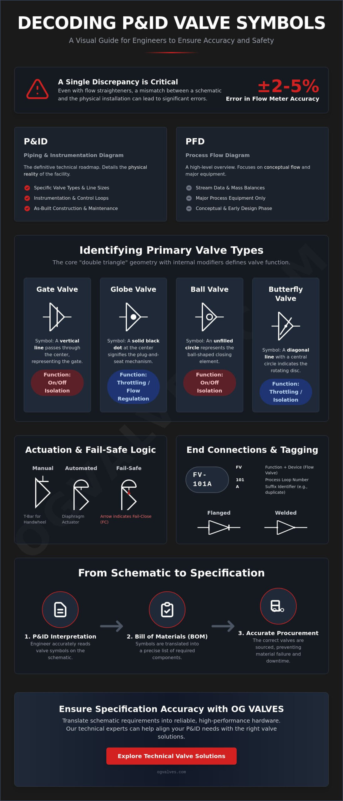
A single discrepancy between a physical installation and its schematic can result in a ±2-5% error in flow meter accuracy, even when flow straighteners are present. For engineers managing critical infrastructure, mastering how to read a valve P&ID symbol with clinical precision is a fundamental safety requirement. You likely recognize that conflicting symbols between ANSI/ISA-5.1-2024 and ISO 10628-2:2012 often create ambiguity that leads to the mis-specification of essential components like globe or butterfly valves.
This guide establishes the technical rigor necessary for interpreting complex schematics across diverse international frameworks. You’ll gain the specific knowledge required to differentiate between basic geometries and complex fail-safe actuation logic. We’ll examine the specific identifiers for gate, ball, and needle valves while detailing the transition from static drawings to intelligent, data-driven digital twins. This systematic approach ensures that procurement and technical audits remain accurate, ultimately reducing operational risk in high-pressure environments.
Key Takeaways
- Distinguish between Process Flow Diagrams and P&IDs to ensure structural and operational clarity within critical industrial infrastructure.
- Master the fundamental “Double Triangle” logic to understand how to read a valve P&ID symbol for gate, ball, and butterfly configurations with clinical accuracy.
- Interpret actuation and fail-safe symbols, such as T-bars and stem indicators, to verify manual or automated logic in high-stakes environments.
- Decipher alphanumeric tagging and end connection markers, including flanged and welded symbols, to prevent errors in technical audits and material selection.
- Bridge the gap between engineering design and procurement by accurately translating P&ID symbols into a comprehensive Bill of Materials.
The Fundamentals of Piping and Instrumentation Diagrams (P&ID)
A Piping and Instrumentation Diagram (P&ID) represents the definitive technical roadmap for process plant construction and maintenance. While a Process Flow Diagram (PFD) focuses on conceptual stream data and mass balances, the P&ID details the physical reality of the facility. This includes every line size, instrument loop, and specific valve type. Mastering how to read a valve P&ID symbol is the prerequisite for any engineer tasked with ensuring that the as-built environment matches the design intent. Without this proficiency, the risk of commissioning errors in heavy industrial sectors increases substantially.
The operational logic of a plant is codified in the Lead Sheet, often referred to as the Legend. This document serves as the project’s primary reference for all graphical notation. Since industrial standards provide a baseline rather than a rigid mandate, individual engineering firms may implement slight variations in symbol modifiers. You must verify the Lead Sheet before interpreting the main schematics to confirm the specific meanings of line weights and valve orientations. This clinical attention to detail prevents the misinterpretation of critical infrastructure components during technical audits.
ISA S5.1 vs. ISO 14617 Standards
Regulatory adherence requires a deep understanding of the differences between North American and European drafting conventions. The ANSI/ISA-5.1-2024 standard governs the majority of domestic industrial projects, emphasizing instrumentation and control logic. Conversely, ISO 14617 and ISO 10628 are frequently mandated for international petrochemical projects. These standards differ in how they depict internal valve trim and fail-safe logic. Familiarity with both sets of standards is essential for engineers involved in global procurement, where a symbol’s geometric nuances dictate the structural soundness of the specified hardware.
The Workflow: From Engineering Design to Procurement
A P&ID isn’t merely a drawing; it’s a functional specification. When an engineer defines a component on a schematic, they’re setting the technical benchmarks for industrial valves. Precision in how to read a valve P&ID symbol ensures that the procurement specialist receives an accurate Bill of Materials (BOM) that accounts for pressure ratings, metallurgy, and end connections. This workflow is the primary safeguard against material failure and unplanned downtime, as it ensures that the physical valve delivered to the site possesses the exact capabilities required for the intended application.
Identifying Primary Valve Types via Geometric Symbols
The foundation of valve symbology is the “double triangle” or bowtie configuration. This geometry represents the valve body and its connection to the process piping. When learning how to read a valve P&ID symbol, you must focus on the internal modifiers that define mechanical function. These markers are standardized by the ANSI/ISA 5.1-2024 standard for P&ID symbols to ensure that engineers and procurement specialists share a common technical language across global supply chains. Precision at this stage prevents the mis-specification of critical components in heavy industrial sectors.
Linear and rotary actions are depicted through distinct visual cues. A vertical line, a solid circle, or a diagonal bar within the body triangles differentiates an isolation valve from a throttling one. These symbols provide the first layer of technical data needed to build an accurate Bill of Materials. If you require specific material classifications or pressure ratings for your project, reviewing a technical valve catalog can help align these schematic symbols with physical hardware requirements.
Linear Motion Valves: Gate and Globe Symbols
Industrial gate valves are identified by a vertical line passing through the center of the double triangle. This line represents the gate or wedge that moves perpendicular to the flow path. In contrast, globe valves feature a solid dot at the intersection. This dot signifies the plug-and-seat mechanism designed for precise flow regulation. While gate symbols imply on/off service, globe symbols indicate a component capable of high-pressure throttling. Additionally, check valves use a “C” or diagonal line to show unidirectional flow, preventing backflow in critical infrastructure.
Quarter-Turn and Specialized Symbols
Rotary valves use circular or diagonal modifiers to denote their 90-degree action. Industrial ball valves are represented by a circle placed at the center of the body triangles. For high-performance applications, butterfly valves utilize a diagonal line through the triangles, representing the disc rotating on a central stem. Plug valves often use a rectangle within the chassis, while needle valves are depicted with an arrow-like point to emphasize their role in fine instrumentation control. Butterfly valve symbols may also include additional notation to distinguish between double-offset and triple-offset designs, which is critical for zero-leakage requirements. Understanding these nuances is vital for how to read a valve P&ID symbol in high-stakes environments where misidentification leads to catastrophic operational failure.
Deciphering Actuation and Fail-Safe Logic Symbols
Beyond the geometric chassis of the valve body, the method of operation defines how a component responds within a control loop. The stem line, extending vertically from the center of the valve symbol, indicates the interface between the internal trim and the external operator. A horizontal “T-bar” at the top of this line signifies manual operation, such as a handwheel or lever. For engineers, understanding how to read a valve P&ID symbol involves analyzing these vertical extensions to determine if a valve is manually throttled or integrated into an automated Safety Instrumented System (SIS). This distinction is critical for maintaining the operational safety of heavy industrial plants.
Reliable schematic interpretation depends on adhering to verified documentation. The Official P&ID Symbol List provided by the U.S. Nuclear Regulatory Commission serves as a benchmark for these operators, ensuring that power generation and petrochemical facilities maintain absolute clarity in their documentation. Misidentifying an actuator type can lead to procurement errors where the wrong power source is specified for critical Gate or Ball valves, resulting in system-wide integration failures.
Automated systems utilize specific shapes to denote the actuator’s power source. A square box represents an electric motor, typically marked with an “M” to indicate its role in remote control loops. Pneumatic diaphragm actuators are depicted by a semi-circle or “umbrella” shape, while hydraulic systems use a diamond modifier. For high-speed safety applications, a solenoid operator is identified by a square containing the letter “S”. These visual markers dictate the technical requirements for the control system’s infrastructure, including electrical wiring or pneumatic tubing runs, and must be verified against the project’s lead sheet.
Fail-Safe Modes: FO, FC, and FL
Fail-safe notation is a non-negotiable safety requirement in heavy industrial sectors. It defines the valve’s default position during a loss of power or signal. The diagram uses arrows or alphanumeric codes near the stem to indicate these states. An arrow pointing toward the valve body signifies Fail Closed (FC), while an arrow pointing away indicates Fail Open (FO). If a valve must retain its current position upon failure, it’s marked as Fail Locked or Fail Last (FL). Spring-return symbols, often shown as a zigzag line within the actuator housing, provide additional confirmation of the mechanical default state. Mastery of how to read a valve P&ID symbol in this context ensures that emergency shutdown procedures are correctly reflected in the plant’s operational logic.
Reading the ‘Fine Print’: Tagging, Materials, and End Connections
Identifying the basic geometry of a valve is insufficient for high-stakes procurement or technical audits. To achieve absolute clarity, you must analyze the alphanumeric data and line markers surrounding the symbol chassis. Mastering how to read a valve P&ID symbol requires an understanding of how these identifiers dictate material selection, mechanical interface, and regulatory adherence. This technical “fine print” ensures the physical component matches the design’s structural requirements and safety benchmarks.
Valve tagging follows a rigid alphanumeric convention. A code such as V-101 generally denotes a manual process valve, while HV-202 indicates a hand-operated or hydraulic component within a specific control loop. These tags correlate directly with the Bill of Materials (BOM) and the project’s master valve list. Beyond tagging, end connection symbols define the physical installation method. Flanged connections are represented by double parallel bars perpendicular to the process line. Welded connections utilize an “X” or a solid dot to signify a permanent joint, while screwed or threaded ends are marked with a small diagonal line. These markers are essential for determining the correct face-to-face dimensions and pressure-retaining capabilities during the procurement phase.
Process and Signal Line Interfacing
Engineers distinguish between primary process lines and secondary sensing or signal lines to define the system’s infrastructure. Process lines are depicted as solid, heavy strokes, while signal lines use specific modifiers. Dashed lines typically represent pneumatic signals, whereas lines with cross-hatches or “hash” marks indicate electronic signals, such as 4-20mA loops. In high-viscosity applications, symbols for heat tracing or jacketed valves include a secondary enclosure line around the valve body. These details are vital for ensuring that the specified gate valves or ball valves are compatible with the plant’s thermal management systems.
Trim and Material Selection Codes
Material specifications and trim codes are often noted adjacent to the valve symbol to ensure durability in corrosive or high-pressure environments. Engineers use these callouts to mandate compliance with standards like API 600 for gate valves or API 6D for pipeline service. In sour gas applications, a “NACE” notation signifies that the valve must meet MR0175/ISO 15156 requirements for sulfide stress cracking resistance. This intersection of symbology and Positive Material Identification (PMI) is a critical safeguard against catastrophic material failure. For projects requiring these rigorous material standards, you should verify your component specifications against the latest API and NACE benchmarks to maintain operational integrity.
From Schematic to Specification: High-Stakes Procurement
The cost of failure in heavy industry is measured in both safety and financial losses. For example, misinterpreting a check valve symbol or its flow direction can lead to severe water hammer or backflow events that compromise the structural integrity of the entire piping system. Quality assurance protocols must ensure that every physical valve delivered to the site matches the schematic’s regulatory intent. This involves verifying material certifications and pressure-testing data against the P&ID’s specific callouts. Adherence to these protocols is a fundamental safeguard in high-pressure petrochemical and power generation environments.
Global Supply and Technical Support
Global infrastructure projects rely on a dependable partner to navigate complex supply chains. Leveraging extensive industrial inventory allows for the fast-track delivery of Gate, Globe, or Butterfly valves to international project sites. Technical experts play a vital role here, cross-referencing P&ID requirements with manufacturer data sheets to ensure absolute compatibility. This rigorous verification process minimizes downtime and prevents the installation of non-compliant hardware. Accuracy in component identification is the primary driver of operational output and long-term reliability.
Final Checklist for P&ID Verification
Before finalizing any procurement order, engineers should follow a systematic verification checklist. Mastery of how to read a valve P&ID symbol is only effective when paired with a methodical review process. Every specification must be anchored in rigorous testing and quality control data. Use the following steps for final validation:
- Verify the Standard: Confirm if the diagram adheres to ISA-5.1-2024 or ISO 10628 conventions.
- Confirm Valve Type: Ensure the geometric markers correctly identify the chassis, such as a Ball, Plug, or Needle valve.
- Analyze Actuation: Verify if the operator is manual, pneumatic, or electric motor-driven.
- Validate Fail-Safe Logic: Confirm the default state (FO, FC, or FL) matches the safety requirements of the loop.
Cross-referencing the P&ID with the official Valve Data Sheet is the only way to guarantee technical accuracy. For specialized procurement needs, engaging with an established global entity ensures that your hardware meets the highest industrial safety standards and regulatory benchmarks.
Standardizing Schematic Interpretation for Operational Excellence
Achieving absolute clarity in process documentation requires an integrated understanding of geometry, actuation logic, and regulatory material standards. This guide has established the technical rigor necessary for interpreting complex schematics across diverse international frameworks, from ISA S5.1 to ISO 14617. Proficiency in how to read a valve P&ID symbol ensures that every physical component aligns with the plant’s design intent and safety protocols. This systematic approach reduces operational risk and prevents the mis-specification of critical infrastructure.
Reliability in heavy industrial sectors is built on the foundation of engineering precision and a clinical focus on durability. We maintain an extensive inventory of API and ISO certified valves, supported by global logistics and fast-track delivery capabilities to meet demanding project timelines. Our specialist technical support team is prepared to verify your specifications against the most rigorous industrial benchmarks. To ensure your procurement matches your technical schematics, Request a Technical Quote for Your Industrial Valve Requirements. Your commitment to standardized precision remains the benchmark for industrial safety and engineering excellence.
Frequently Asked Questions
What is the difference between a gate valve and a globe valve symbol on a P&ID?
Gate valves are represented by a vertical line passing through the center of the double-triangle chassis, signifying the perpendicular movement of the wedge. Globe valves utilize a solid dot at the intersection of the triangles to denote the plug-and-seat mechanism. This distinction is vital for determining if a component is intended for isolation or throttling service in high-pressure systems. Misidentifying these symbols can lead to improper flow regulation and premature trim wear.
How do I identify a fail-safe position for an automated valve in a diagram?
Fail-safe positions are identified by arrows located on the valve stem or by specific alphanumeric codes like FC (Fail Closed) and FO (Fail Open). An arrow pointing toward the valve body indicates the component will close upon loss of power or signal. Understanding how to read a valve P&ID symbol in this context is a critical safety requirement for emergency shutdown logic and risk mitigation in petrochemical environments.
Are P&ID valve symbols standardized across all industries globally?
While international standards like ANSI/ISA-5.1-2024 and ISO 10628-2:2012 provide a uniform framework, site-specific variations often exist. Engineers must consult the project’s lead sheet or legend to account for these nuances. Global procurement requires a clinical focus on these standards to prevent the mis-specification of hardware across different regulatory jurisdictions. Reliability depends on verifying the specific standard used by the drafting entity before finalizing a Bill of Materials.
What does a circle inside the valve triangle indicate?
A circle positioned at the intersection of the two triangles indicates a ball valve. This symbol represents the rotary action of the internal ball. In some advanced schematics, the circle’s size or additional internal lines might differentiate between standard and full-bore configurations. This visual clarity ensures that the flow characteristics required by the process design are accurately reflected in the physical hardware selected for the installation.
How are 3-way and 4-way valves represented in process schematics?
Multi-port valves are depicted by adding additional triangles to the standard bowtie chassis to represent the third or fourth flow path. These symbols often include internal lines or arrows to define the specific flow pattern, such as “L-port” or “T-port” configurations. Accurate interpretation of these symbols is essential for complex diversion or mixing applications where fluid routing is critical to the process’s chemical or thermal balance.
What does the ‘S’ or ‘M’ modifier above a valve symbol mean?
The ‘S’ and ‘M’ modifiers indicate the specific type of actuator driving the valve stem. ‘S’ denotes a solenoid operator, commonly used in safety instrumented systems for rapid response. ‘M’ represents an electric motor actuator integrated into a continuous control loop. These identifiers dictate the necessary electrical infrastructure and signal requirements for the automated component within the plant’s larger control architecture and power distribution system.
How do I distinguish between flanged and welded end connections on a P&ID?
Flanged connections are marked by two parallel bars perpendicular to the process line at the valve’s inlet and outlet. Welded connections are shown with an ‘X’ or a solid dot at the joint to signify a permanent, pressure-retaining seal. These markers are critical for calculating face-to-face dimensions and ensuring the mechanical integrity of the piping system matches the schematic’s technical requirements during the procurement phase.
Why do some valve symbols have a diagonal line through the center?
A diagonal line through the double-triangle chassis typically identifies a butterfly valve, representing the disc rotating on a central axis. In some contexts, a diagonal line might also denote specific check valve designs or high-performance rotary components. Mastering how to read a valve P&ID symbol involves cross-referencing these geometric modifiers with the project legend to ensure the correct valve type is procured for high-stakes industrial applications.
 Responsive Menu