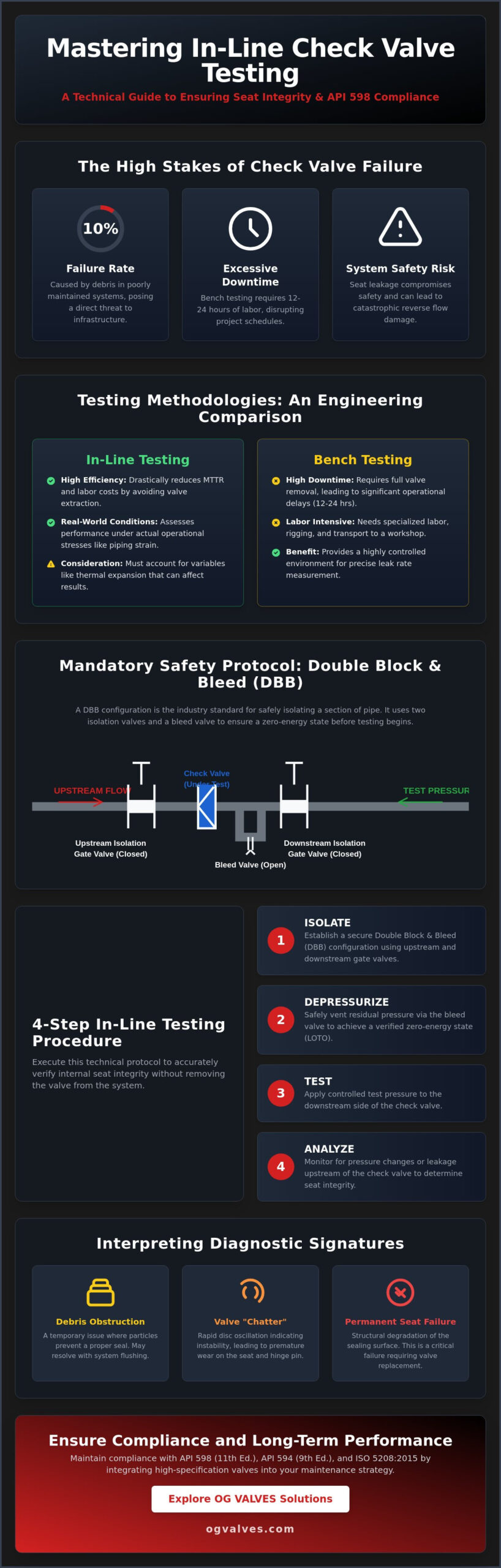
In poorly maintained industrial systems, backflow failures caused by debris result in a 10% failure rate for check valves; this level of degradation poses a direct threat to high-pressure infrastructure. You likely recognize that removing these critical components for bench testing creates excessive operational downtime that your project schedule cannot afford. However, ignoring potential seat leakage compromises system safety and risks non-compliance with international engineering standards.
This technical guide details the precise protocols for how to test a check valve in-line to verify seat integrity and ensure compliance with the 11th Edition of API 598, published in February 2023. By mastering these diagnostic procedures, you’ll accurately identify internal leakage without extracting the valve from the piping system. Our analysis covers isolation methodologies, differential pressure verification, and the specific performance requirements outlined in the 9th Edition of API 594 and ISO 5208:2015 to maintain the highest levels of industrial safety and operational reliability.
Key Takeaways
- Identify why in-line verification is essential for protecting upstream pumps and compressors from catastrophic reverse flow damage.
- Establish a secure testing environment by utilizing a Double Block and Bleed configuration with redundant isolation gate valves.
- Execute the technical protocol for how to test a check valve in-line using controlled downstream pressure to verify internal seat integrity.
- It’s essential to analyze diagnostic signatures to distinguish between temporary debris obstructions and permanent mechanical seat failure.
- Maintain compliance with API 598 (11th Edition) and ISO 5208:2015 by integrating high-specification materials into your maintenance strategy.
The Critical Necessity of In-Line Check Valve Verification
In-line check valve verification is the systematic assessment of seat integrity and mechanical disc functionality while the component remains within the operational piping system. This process is a fundamental requirement for maintaining the reliability of safety instrumented systems (SIS). The primary objective is the prevention of reverse flow; this phenomenon can cause catastrophic mechanical failure in upstream assets such as centrifugal pumps or reciprocating compressors. By establishing a rigorous protocol for how to test a check valve in-line, engineers ensure that the pressure boundary remains secure without the extensive labor costs associated with valve extraction.
The economic advantages of in-line diagnostics are quantifiable through the reduction of Mean Time to Repair (MTTR). In high-pressure industrial environments, removing a flanged or butt-welded valve for bench testing often requires 12 to 24 hours of specialized labor and rigging. In-line testing protocols significantly compress this timeline, allowing for rapid verification of system readiness. Beyond efficiency, this practice ensures strict compliance with safety management systems and international environmental protocols, such as those governed by API 598 and ISO 5208:2015.
Industrial Failure Modes and Their Indicators
Mechanical degradation often manifests as “chatter,” a condition where the disc oscillates rapidly against the seat or stop. This behavior leads to premature wear of the hinge pin and seat surfaces, eventually compromising the valve’s ability to provide a bubble-tight seal. High-stakes trust in industrial valves depends on the early detection of these failure modes. Engineers must recognize reverse flow signatures, such as downstream pressure fluctuations or abnormal acoustic profiles, which indicate that the internal seal is no longer maintaining the required pressure boundary.
In-Line vs. Bench Testing: An Engineering Comparison
Evaluating the performance of a check valve in-line relies heavily on differential pressure monitoring. While hydrostatic shop tests provide a controlled environment for leak rate measurement, they don’t account for the real-world stresses of the installed piping. However, in-line diagnostics must account for variables like thermal expansion, which can distort diagnostic results if the system hasn’t reached thermal equilibrium. While in-line methods are highly effective for routine verification, full removal remains mandatory if the diagnostic signatures suggest major structural fatigue or if seat leakage exceeds the specific tolerances defined in API 594 (9th Edition).
Pre-Test Requirements: Isolation and Safety Protocols
The integrity of a check valve verification procedure depends entirely on the security of the isolation boundary. Engineers shouldn’t attempt to execute how to test a check valve in-line without first establishing a redundant isolation zone. This requires the deployment of high-specification gate valves both upstream and downstream of the test subject. A Double Block and Bleed (DBB) configuration is the mandatory industrial standard for this setup. By utilizing two isolation points with a bleed valve in between, you ensure that any leakage from the main process line is diverted, preventing it from skewing the test data or creating a safety hazard.
Media compatibility is another critical technical consideration. The test fluid, whether liquid or gas, must align with the process media to prevent cross-contamination or chemical reactions that could damage internal seat materials. Additionally, data integrity requires that all pressure gauges used during the test cycle carry a current calibration certificate. For high-stakes industrial environments, gauges should offer a minimum accuracy of ±0.5% of the full-scale reading. If you’re upgrading your infrastructure to meet these rigorous demands, consider the long-term reliability of industrial check valves designed for high-pressure service.
System Depressurisation and Venting
Before beginning seat integrity assessments, the system must reach a zero-energy state. Residual pressure must be safely vented to a flare system or a dedicated containment vessel. Engineers must verify the absence of pressure using redundant monitoring points. Lock-out/tag-out (LOTO) procedures are strictly enforced during this phase to ensure that no accidental valve actuation occurs while the test boundary is active. This methodical approach eliminates the risk of high-pressure release during the diagnostic phase.
Technical Documentation and Standards Compliance
All in-line testing protocols must align with the 11th Edition of API 598, published in February 2023. This standard defines the specific closure test requirements and durations necessary for validating valve performance. Adhering to API 598 Testing Standards ensures that the results are legally and technically defensible. Documentation must include baseline ambient temperatures to adjust for pressure-temperature (P-T) ratings as specified in ASME B16.34. Recording these variables is essential for an accurate interpretation of how to test a check valve in-line under varying field conditions.
Step-by-Step Procedure for In-Line Seat Integrity Testing
Executing a precise protocol for how to test a check valve in-line requires a methodical approach to pressure application and monitoring. Once the isolation boundary is verified through the Double Block and Bleed configuration, you must isolate the check valve by closing the primary upstream and downstream isolation valves. A controlled pressure source, typically a high-pressure nitrogen cylinder or a hydrostatic test pump, is then connected to the downstream side of the check valve. This orientation is critical because it simulates the backflow conditions the valve is designed to prevent. You must introduce the test medium slowly to avoid pressure spikes that could cause mechanical shock to the internal disc or hinge assembly.
Monitoring the upstream side for leakage is the most critical phase of the procedure. With the downstream side pressurized, you must open the upstream vent port or bleed valve to observe any fluid accumulation or pressure increase. Engineers must measure the leakage rate against the specific allowable limits defined by API Valve Inspection and Testing protocols. For a successful verification, the pressure must remain stabilized for a minimum duration, typically between 60 to 120 seconds depending on the valve size, to ensure no slow-seeping failures exist that might be missed during a rapid cycle.
Differential Pressure Monitoring
Calculating the required test pressure is a function of the valve’s maximum rated working pressure (MWP). For seat integrity tests, the pressure is typically maintained at 110% of the MWP. In gaseous systems, you should utilize high-accuracy electronic transducers rather than analog gauges to detect micro-leakage. Interpreting pressure decay curves is essential here. A steady decline in pressure often indicates seat leakage, whereas a rapid initial drop followed by stabilization usually points to thermal cooling of the test medium as it enters the piping system.
Testing Nuances for Different Valve Designs
Diagnostic Interpretation and Troubleshooting
Identifying the root cause of a failed integrity test is as critical as the execution of the test itself. When you implement the protocol for how to test a check valve in-line, the resulting data must be scrutinized for specific failure signatures. A fluctuating leakage rate during the stabilization period often suggests debris entrapment on the seating surface rather than structural damage. Conversely, a steady, linear pressure decay usually indicates permanent seat deformation or material loss. Industry data indicates that 15% of lower-quality valves experience these leakage problems within the first five years of service, highlighting the necessity of precise diagnostic analysis.
Water hammer events leave distinct diagnostic signatures on check valves that are detectable through specialized monitoring. These signatures include high-intensity acoustic “thumps” and physical deformation of the clapper or hinge pin assembly. If your in-line test reveals a seal failure despite a clean system, you must correlate these results with upstream pressure surges recorded in the SCADA logs. In highly regulated sectors like nuclear power, where premature degradation is limited to 1% or 2% of the valve population, this level of forensic correlation is mandatory for maintaining system-wide safety standards.
Addressing Seat Leakage and Scaling
In-line flushing can sometimes remediate minor seat obstructions without requiring a full teardown. By cycling the valve under high-velocity flow conditions, particulates may be dislodged from the seating interface. However, if diagnostics reveal “wire-drawing” marks-narrow, high-velocity erosion channels on the seat-the integrity is permanently compromised. These marks indicate that the medium has bypassed the seal at extreme speeds, typically requiring a full internal inspection and component replacement. If your current infrastructure fails these rigorous integrity tests, review our high-specification industrial check valves designed for extreme service conditions.
Acoustic and Ultrasonic Diagnostics
Ultrasonic leak detection is a non-invasive diagnostic for valve integrity that identifies turbulent flow frequencies invisible to the naked eye. In high-noise environments, these tools pinpoint the exact location of a bypass by filtering out ambient mechanical noise. Lower frequencies often suggest mechanical binding of the clapper or hinge, while high-frequency profiles correlate with micro-leakage across the seat. Correctly interpreting these acoustic signatures is a vital component of how to test a check valve in-line while maintaining operational continuity.
Establishing long-term reliability in high-pressure systems requires more than just knowing how to test a check valve in-line; it requires components engineered for extreme durability. OG VALVES LTD. focuses on providing check valves that exceed the minimum requirements of the 11th Edition of API 598. By prioritizing industrial precision, we ensure that your system-wide safety boundaries remain intact even under severe service conditions. Our clinical focus on engineering excellence minimizes the risk of backflow, protecting your upstream assets from the mechanical stresses identified in previous sections.
Seat degradation remains a primary driver of testing failures in the oil and gas sectors. We utilize advanced material grades, such as forged steel and specialized alloys, to resist the erosive effects of high-velocity bypass. This focus on metallurgical excellence directly addresses the 15% leakage rate reported by users of sub-standard equipment within their first five years of operation. By sourcing components that maintain seat integrity over thousands of cycles, you reduce the frequency of failed in-line tests and the subsequent operational downtime required for valve extraction.
Material Integrity and Specification
High-pressure and high-temperature cycles demand uncompromising material traceability and compliance. OG VALVES LTD. maintains comprehensive documentation for every component, ensuring adherence to ASME B16.34 and project-specific safety management systems. Our engineering team supports specialists in the procurement of high-performance ball valves and check valves for critical infrastructure. This specialized material selection, including forged steel and cryogenic service grades, ensures that the valve’s pressure-temperature ratings remain stable throughout its service life.
Global Supply Chain and Technical Expertise
Our global entity operates as a dependable partner in large-scale industrial projects rather than a mere vendor. We leverage an extensive inventory of API-certified valves to minimize operational downtime during critical replacement cycles. Expert technical consultation is available for precise valve sizing and selection, ensuring that every installation is optimized for its specific flow profile and pressure requirements. This methodical approach to project management ensures that technical data is communicated without ambiguity. For technical assistance or procurement inquiries, contact OG VALVES LTD. for high-integrity industrial valve solutions.
Advancing Industrial Safety Through Rigorous Diagnostic Protocols
Mastering the technical requirements for how to test a check valve in-line ensures that your infrastructure remains compliant with the 11th Edition of API 598. This methodical approach to seat integrity verification prevents the 10% failure rate commonly seen in debris-laden systems without the operational penalties of valve removal. By integrating redundant isolation through Double Block and Bleed configurations and utilizing ultrasonic diagnostics, engineers accurately identify mechanical wear before it leads to catastrophic reverse flow. Maintaining these high standards of precision is essential for protecting upstream pumps and compressors in high-pressure environments.
Reliable performance depends on sourcing components built for extreme service. OG Valves maintains an extensive inventory of API-certified industrial valves and provides specialist technical support for global heavy industry projects. Our commitment to quality ensures fast-track delivery for critical infrastructure components, allowing you to maintain project schedules without compromising on engineering excellence. If your current systems require high-integrity upgrades, Request a Technical Quote for Industrial Check Valves to secure your pressure boundaries with proven technology. It’s a strategic investment in the long-term durability of your facility.
Frequently Asked Questions
Can I test a check valve in-line while the system is fully operational?
No, you cannot test a check valve in-line while the system is fully operational. The procedure requires the component to be isolated from the main flow to establish a zero-energy state and prevent process interference. Establishing a Double Block and Bleed boundary is a mandatory safety requirement for high-pressure industrial applications. This ensures that the test pressure source remains the only variable influencing the diagnostic data.
What is the allowable leakage rate for an industrial check valve under API 598?
Allowable leakage rates are defined in Table 6 of the 11th Edition of API 598. For metal-seated check valves, the standard permits zero leakage for liquid tests in valves up to 4 inches in diameter; larger sizes allow for a specific drop-per-minute count. Resilient-seated valves must demonstrate zero visible leakage for the entire duration of the closure test. These quantifiable limits ensure the pressure boundary meets rigorous industrial safety specifications.
How often should in-line check valve testing be performed in oil and gas applications?
Testing intervals are generally determined by the Safety Integrity Level (SIL) of the system and typically range from 12 to 36 months. In critical infrastructure, engineers often align these tests with planned turnaround cycles to minimize production impacts. Systems handling corrosive or abrasive media may require more frequent verification, potentially every 6 months, to monitor for accelerated seat erosion or metallurgical degradation.
What equipment is required for a professional in-line check valve test?
A professional test requires high-accuracy calibrated gauges, a regulated pressure source, and specialized connection fittings. You’ll need electronic transducers with a minimum accuracy of ±0.5% to detect micro-leakage in gaseous systems. Additionally, the setup must include vent ports on the upstream side to monitor for bypassed media. These tools are essential for executing how to test a check valve in-line with technical precision.
Is it possible to test a check valve using compressed air if it normally carries liquid?
Testing with compressed air is permissible for low-pressure seat verification but requires strict adherence to safety protocols. Air tests are typically conducted at 60 to 80 psi (4 to 5.5 bar) to identify initial seating issues. However, if the valve is designed for high-pressure liquid service, a hydrostatic test at 110% of the maximum working pressure is necessary to validate structural integrity under operational loads.
What are the signs of a failing check valve before performing a pressure test?
Physical indicators include audible chatter, excessive vibration in the piping, or abnormal upstream pressure spikes. If you notice a pump spinning backward during shutdown, it’s a definitive sign of check valve failure. These mechanical signatures often precede total seal loss and serve as early warnings. Identifying these symptoms allows for proactive maintenance before a full diagnostic pressure test confirms the extent of the internal damage.
How does a non-slam check valve differ during in-line testing procedures?
Non-slam check valves require a more nuanced assessment of spring-assisted closure speed. During the test, the disc must reach the seat before the backflow pressure peaks to prevent mechanical shock. You must verify that the internal spring provides sufficient force to initiate seat contact in zero-flow conditions. This differs from standard swing designs that rely primarily on gravity or high-velocity backflow to achieve a seal.
Can in-line testing detect a broken spring in a lift check valve?
Yes, differential pressure monitoring can identify a compromised internal spring. When you implement the protocol for how to test a check valve in-line, a broken spring often prevents the disc from seating at low differential pressures. If the valve only seals when high pressure is applied, it indicates the mechanical assist is no longer functional. This condition requires immediate internal inspection to prevent disc oscillation and subsequent hinge pin fatigue.
 Responsive Menu