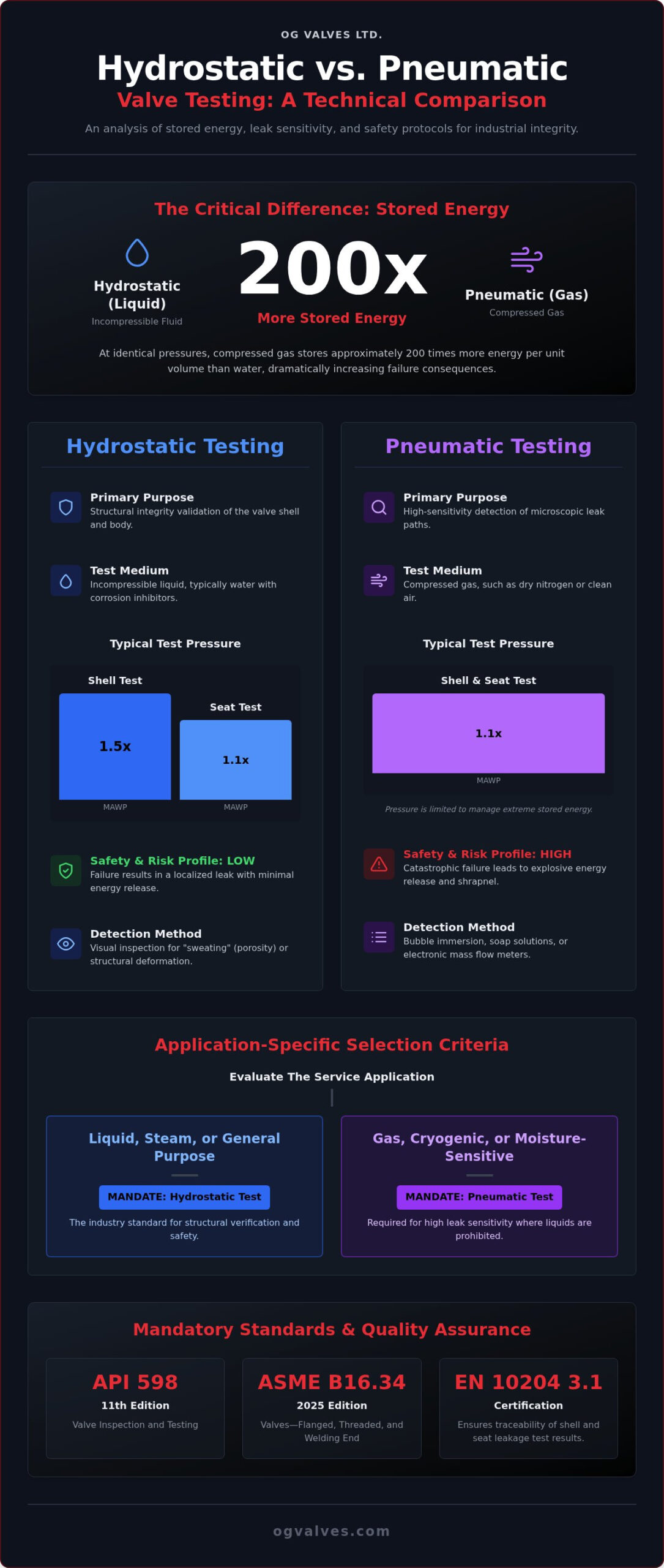
Compressed gas stores approximately 200 times more energy per unit volume than water at an identical pressure, transforming a routine validation into a high-stakes safety event. Engineers understand that the decision between hydrostatic vs pneumatic valve testing is rarely a matter of convenience; it’s a calculated assessment of stored energy risks and material compatibility. You’re likely managing the tension between the need for absolute seat tightness and the strict safety protocols required by high-pressure gas applications.
This technical analysis delivers a definitive comparison of these pressure testing methodologies to ensure both industrial valve integrity and regulatory compliance. We provide the data necessary to align your quality control processes with the 11th Edition of API 598 and the 2025 Edition of ASME B16.34. By examining the clinical differences in leak detection sensitivity and the potential for water-based corrosion, this guide clarifies exactly when to mandate specific test mediums for your gate, ball, or check valves. We conclude with a detailed look at risk mitigation strategies for high-pressure systems.
Key Takeaways
- Analyze the divergent stored energy profiles of incompressible fluids versus compressed gases to mitigate catastrophic failure risks during pressure containment verification.
- Differentiate between the structural integrity validation of hydrostatic testing and the superior leak-path sensitivity offered by pneumatic testing for specialized gas applications.
- Identify the mandatory selection criteria for hydrostatic vs pneumatic valve testing based on the latest 2025 ASME B16.34 and 11th Edition API 598 standards.
- Implement rigorous procurement standards by mandating EN 10204 3.1 certification to ensure total traceability of shell and seat leakage testing results.
Core Principles of Hydrostatic and Pneumatic Valve Testing
The validation of pressure-containing components is a fundamental requirement for industrial safety and regulatory adherence. In the technical evaluation of hydrostatic vs pneumatic valve testing, the selection of the medium depends on the physical properties of the fluid and the specific operational environment of the valve. The primary objective remains the verification of the pressure boundary, ensuring that the shell and seat can withstand stresses exceeding the Maximum Allowable Working Pressure (MAWP). Engineers must balance the need for structural verification with the sensitivity required to detect microscopic leak paths.
The Mechanism of Hydrostatic Shell and Seat Tests
Hydrostatic testing is the standard procedure for verifying the structural soundness of the valve body and its internal components. This process involves the complete evacuation of air from the valve cavity, followed by the introduction of an incompressible liquid, typically water treated with corrosion inhibitors to prevent material degradation. According to the Core Principles of Hydrostatic Testing, the test pressure for the shell is usually maintained at 1.5 times the rated working pressure at 100°F (38°C). This ensures that the casting or forging can handle the mechanical loads of the system.
Technicians monitor the external surfaces for “sweating,” which indicates porosity in castings, or visible structural deformation. Seat tests are typically conducted at 1.1 times the rated pressure. The lack of compressibility in the test medium ensures that if a rupture occurs, the release of kinetic energy is minimal, significantly reducing the risk of catastrophic equipment failure. This method is the default for most industrial valves used in liquid service or high-pressure steam applications.
The Mechanism of High-Pressure Pneumatic Testing
Pneumatic testing utilizes compressed gases, such as dry nitrogen or clean air, to identify minute leak paths that might be bridged by the surface tension of water. Because gas molecules are smaller and more mobile, this method provides superior sensitivity for detecting microscopic defects in seat seals. The test pressure is typically restricted to 1.1 times the MAWP to manage the high levels of stored potential energy inherent in compressed gases. It’s a precise methodology that demands rigorous safety protocols.
Common detection methods include:
- Immersion of the pressurized valve in a water tank to observe bubble formation at the seat or stem.
- Application of bubble-forming solutions to critical joints, seals, and gaskets.
- Utilization of electronic mass flow meters for quantifiable leakage measurement in high-purity systems.
This methodology is essential for valves intended for low-pressure gas service or applications where moisture contamination is prohibited, such as cryogenic or oxygen systems. While pneumatic testing offers high sensitivity, it requires stringent safety exclusion zones due to the massive increase in stored energy compared to hydrostatic methods. It doesn’t replace the structural verification of a hydrotest but acts as a specialized supplement for specific service requirements.
Comparative Analysis: Energy Levels, Sensitivity, and Safety
The divergence in safety profiles between hydrostatic vs pneumatic valve testing stems fundamentally from the physical properties of the test medium. While hydrostatic testing remains the industrial default for structural verification, pneumatic methods are often necessitated by application-specific leak sensitivity requirements. The decision to employ one over the other involves a clinical assessment of stored energy risks versus the necessity for detecting microscopic leak paths that liquid mediums might fail to reveal.
Stored Kinetic Energy and Failure Consequences
Water is nearly incompressible, meaning a failure during a hydrostatic test typically results in a rapid pressure drop and a localized leak. Compressed gas behaves differently. Because gas stores approximately 200 times more energy per unit volume than water at an identical pressure, the failure consequences are significantly more severe. A catastrophic shell breach during high-pressure pneumatic testing releases this potential energy instantaneously, resulting in shockwaves and high-velocity shrapnel.
Engineering teams often calculate the “TNT equivalent” energy of a pneumatic test to determine the required radius for safety exclusion zones. These calculations dictate the necessity for blast-resistant enclosures or remote testing bunkers. Adhering to ASME B16.34 Compliance ensures that the valve body design accounts for these stresses, yet the inherent risk of gas expansion remains a primary reason why hydrostatic testing is preferred for general industrial plumbing and high-pressure steam systems.
Leak Detection Sensitivity and Fluid Properties
Pneumatic testing offers superior sensitivity due to the molecular size of the test medium. Gas molecules, such as nitrogen or helium, penetrate smaller orifices than water molecules. The surface tension of water can effectively bridge minute cracks or seat imperfections, temporarily masking leaks that would be evident under gas pressure. This makes pneumatic seat tests essential for gas service applications where even negligible leakage rates are unacceptable.
When selecting butterfly valves for high-purity gas systems or vacuum service, pneumatic validation is the only method that ensures long-term performance. Fluid compatibility is another decisive factor. Water-based testing can introduce moisture that leads to internal corrosion or catastrophic contamination in oxygen or cryogenic systems. In these specialized environments, dry nitrogen is the mandatory medium. If you require guidance on aligning testing protocols with specific material classifications, you can contact our technical experts for a detailed specification review.
International Standards: API 598 and ASME B16.34 Compliance
Global industrial infrastructure relies on standardized validation protocols to ensure the reliability of pressure-containing equipment. When evaluating hydrostatic vs pneumatic valve testing, engineering specifications must align with the 11th Edition of API 598 and the 2025 Edition of ASME B16.34. These benchmarks provide the technical framework for verifying that check valves, gate valves, and ball valves can perform under extreme operational stresses without compromise. Adherence to these standards isn’t optional; it’s a prerequisite for high-stakes industrial trust.
API 598 Requirements for Shell and Seat Testing
API 598 is the primary standard for industrial valve inspection. It mandates specific hydrostatic shell test durations that scale with the Nominal Pipe Size (NPS). For instance, valves with an NPS of 2 or smaller require a minimum holding time of 15 seconds. Those NPS 14 or larger demand at least 300 seconds to ensure structural integrity. These durations allow for the thorough observation of the body and stem seals under 1.5 times the rated working pressure.
The standard also defines stringent allowable leakage rates for seat tests. Resilient-seated valves, such as those with Teflon or elastomer seals, must demonstrate zero visible leakage during the test duration. Metal-seated valves are permitted a specific number of drops per minute based on the valve type and size. While hydrostatic methods are the default, API 598 permits pneumatic testing as a substitute for low-pressure closure tests or when specified by the purchaser for high-pressure applications. This flexibility is supported by documents like the ISA Hydrostatic Testing of Control Valves, which further refines testing parameters for automated systems.
ASME B16.34 and Pressure-Temperature Ratings
ASME B16.34 provides the foundational criteria for valve design, focusing on pressure-temperature ratings and material classifications. The test pressure isn’t a static value; it’s calculated based on the material group and the maximum allowable pressure at the specified temperature class. This ensures the valve body is capable of withstanding the mechanical loads encountered in heavy industrial service. It’s a clinical approach to casting integrity that’s vital for high-stakes environments.
The standard requires a shell test at 1.5 times the 100°F (38°C) pressure rating. The “Special Class” designation within ASME B16.34 mandates additional non-destructive examination (NDE) such as radiography or ultrasonic testing. These enhanced protocols, combined with rigorous hydrostatic validation, ensure that the valve meets the highest global safety benchmarks. By following these structured requirements, engineers mitigate the risk of catastrophic failure in high-pressure systems.
Application-Specific Selection: When to Choose Pneumatic vs. Hydrostatic
While international standards establish the procedural framework, the specific industrial application dictates the technically appropriate medium. In the technical assessment of hydrostatic vs pneumatic valve testing, engineers must evaluate the long-term impact of the test fluid on the valve internals and the broader system. Hydrostatic testing remains the primary choice for liquid service, high-pressure steam, and general industrial plumbing. It provides a reliable structural baseline for the pressure boundary. However, the introduction of water necessitates rigorous post-test procedures. Residual moisture can lead to localized corrosion or the degradation of soft-seated materials if the valve isn’t immediately dried and treated with inhibitors.
Testing for Oxygen and Cryogenic Service
Oxygen-rich environments strictly prohibit the presence of hydrocarbons and moisture. Even minute traces of water can lead to catastrophic failure or flash fires in these systems. For cryogenic valves, residual moisture freezes at operational temperatures, causing seat damage or mechanical seizure of the stem. Pneumatic testing with dry nitrogen or helium is the only viable methodology for these systems. This approach maintains the high-purity requirements of the process and avoids the intensive cleaning and degreasing protocols required after any fluid exposure. It’s a clinical requirement for maintaining the integrity of the specialized seals used in these environments.
Field Testing vs. Factory Acceptance Testing (FAT)
Factory Acceptance Testing (FAT) allows for controlled environments where high-pressure pneumatic tests can be conducted within blast-resistant enclosures. This level of control is rarely available during field commissioning. Field testing presents significant structural limitations; filling a large-bore pipeline with water for a hydrostatic test significantly increases the static load on pipe supports, often requiring temporary reinforcement. Drainage also presents a logistical challenge, as large volumes of test water must be treated or disposed of according to environmental regulations.
Integrating actuators into the pressure test cycle during FAT is essential for automated systems. This validates that the actuator’s torque output is sufficient to maintain seat integrity under full differential pressure. Ensuring that your procurement specifications account for these application-specific nuances is critical for long-term operational reliability and safety. To align your material specifications with the appropriate testing protocol, partner with OG VALVES LTD. for technical guidance on your next infrastructure project.
Quality Assurance in Procurement: Documentation and Certification
The transition from engineering specification to field installation requires a clinical focus on documentation. Procurement specialists must ensure all industrial valves arrive with verifiable test reports that confirm the successful completion of the mandated pressure cycles. In the technical assessment of hydrostatic vs pneumatic valve testing, the choice of medium isn’t just a technical preference. It’s a recorded variable that must align perfectly with the project’s Quality Control Plan (QCP).
EN 10204 3.1 and 3.2 certifications represent the gold standard for traceability in the energy and chemical sectors. A 3.1 certificate is issued by the manufacturer’s authorized representative, independent of the production department. A 3.2 certificate requires an additional independent inspector or third-party agency. These documents provide the necessary validation for high-stakes projects, such as offshore platforms or nuclear facilities, where the cost of component failure is unacceptable. It’s the only way to prove that a valve doesn’t just look the part but actually meets the pressure rating.
Understanding Test Certificates and Traceability
Verifying a valve test report involves more than checking for a signature. Technicians must confirm the specific test pressure, the holding duration, and the test medium used. These data points should be cross-referenced with the heat numbers stamped on the valve body and the corresponding Material Test Reports (MTRs). This ensures that the physical component matches the metallurgical and pressure-testing data provided. Compliance with the QCP ensures that every ball, gate, or globe valve meets the specific safety thresholds required for the intended service. If the report doesn’t explicitly state the medium used, it’s impossible to confirm if the valve is suitable for dry gas or liquid service.
Mitigating Risk in the Global Supply Chain
Managing global supply chains requires a partner that understands the nuances of technical auditing. OG VALVES conducts rigorous evaluations of manufacturing facilities to ensure consistent adherence to international benchmarks. This oversight is critical when managing fast-track delivery schedules where the pressure to bypass protocols can increase. We maintain 100% testing compliance even under tight project timelines, ensuring that speed never compromises the structural integrity of the valve. Our process guarantees that every component is ready for immediate integration into critical infrastructure.
Technical expertise is vital when procuring specialized alloys like Super Duplex or Inconel. These materials require precise handling and specific test parameters to avoid stress-induced cracking or surface contamination. Our support team assists in selecting the optimal test medium and pressure levels for these complex specifications. OG VALVES ensures every component undergoes exhaustive shell and seat testing before global dispatch. Third-party witness testing provides an additional layer of validation, often required for high-stakes projects where external verification is mandatory for regulatory adherence.
Standardizing Pressure Containment Verification for Critical Infrastructure
The technical selection of hydrostatic vs pneumatic valve testing is a clinical decision based on stored energy management and fluid compatibility. While hydrostatic testing remains the benchmark for structural integrity, pneumatic methods provide the sensitivity required for high-purity gas service. Adhering to the 11th Edition of API 598 and the 2025 Edition of ASME B16.34 ensures that your infrastructure meets global safety benchmarks. It’s essential to align these protocols with specific material classifications to avoid long-term operational failure.
OG VALVES maintains an extensive inventory of API-compliant valves supported by global fast-track delivery capabilities. We guarantee EN 10204 3.1 traceability for all components, ensuring that your procurement process remains rigorous and transparent. Our team understands the technical nuances of shell and seat validation for specialized alloys and complex material specifications. We’re ready to support your next project with precision-engineered solutions.
Request a Technical Quote for API-Tested Industrial Valves
Secure your operations with components validated to the highest industrial standards.
Frequently Asked Questions
Is pneumatic testing more sensitive than hydrostatic testing?
Pneumatic testing is significantly more sensitive than hydrostatic testing due to the molecular size of the test medium. Gas molecules, such as nitrogen, penetrate minute orifices that the surface tension of water would otherwise seal. This makes gas the preferred medium for detecting microscopic leak paths in high-purity gas or vacuum systems. It’s a critical distinction in the technical comparison of hydrostatic vs pneumatic valve testing for specialized industrial applications.
Can hydrostatic testing be substituted for pneumatic testing under API 598?
API 598 allows the substitution of pneumatic testing for hydrostatic testing under specific conditions. It’s typically permitted for low-pressure closure tests or when the purchaser explicitly specifies a high-pressure pneumatic test. However, the standard maintains hydrostatic testing as the primary method for shell integrity verification. Technicians must ensure that the test facility meets the rigorous safety requirements for high-pressure gas expansion before proceeding with any substitution.
What are the primary safety risks associated with pneumatic valve testing?
The primary safety risk in pneumatic testing is the massive amount of stored potential energy within the compressed gas. Because gas is highly compressible, a structural failure releases this energy instantaneously, potentially resulting in catastrophic explosions, high-velocity shrapnel, and powerful shockwaves. This necessitates the implementation of strict exclusion zones and blast-shielding protocols. These risks are why hydrostatic methods are the industrial default for structural validation of most valve architectures.
Why is water usually preferred over gas for high-pressure shell tests?
Water is preferred for high-pressure shell tests because it’s nearly incompressible. In the event of a material failure or casting defect, the pressure drops almost immediately, resulting in a localized leak rather than an explosive release of energy. This inherent safety profile allows for closer inspection of the valve body under stress. It provides a reliable means of verifying structural soundness without the extreme safety hazards associated with high-pressure gas expansion.
What is the standard test pressure for a hydrostatic shell test?
The standard test pressure for a hydrostatic shell test is 1.5 times the maximum allowable working pressure (MAWP) at 100°F (38°C). This pressure level is defined by ASME B16.34 to ensure the valve body and stem seals can withstand stresses beyond their operational limits. It’s a clinical baseline used to identify porosity or structural weaknesses in the casting. All test results must be documented on the EN 10204 3.1 certificate for traceability.
Does hydrostatic testing cause corrosion in carbon steel valves?
Hydrostatic testing can cause internal corrosion in carbon steel valves if the test water isn’t treated or removed. To mitigate this risk, technicians utilize water containing corrosion inhibitors and ensure the valve is thoroughly dried post-test. In systems where moisture is strictly prohibited, such as oxygen or cryogenic service, engineers typically mandate a dry pneumatic test. This prevents the formation of rust or material degradation that could compromise seat integrity.
How long must a valve hold pressure during an API 598 test?
Holding times under API 598 are determined by the Nominal Pipe Size (NPS) of the valve. Smaller valves typically require a minimum duration of 15 seconds for a valid pressure check. For larger infrastructure components, the holding time can extend to 300 seconds or more. This duration ensures sufficient time for a thorough visual inspection of the shell and seat under full test pressure, confirming the absence of any visible leakage.
What is the difference between a shell test and a seat test?
A shell test verifies the structural integrity of the valve body, bonnet, and stem seals at 1.5 times the rated pressure. A seat test specifically evaluates the closure mechanism’s ability to prevent leakage across the valve port, typically conducted at 1.1 times the rated pressure. Both are essential components of hydrostatic vs pneumatic valve testing protocols. While the shell test focuses on pressure containment, the seat test ensures operational tightness during service.
 Responsive Menu