In high-pressure process loops, the margin between operational stability and catastrophic system failure often rests on a component no larger than a technician’s thumb. For engineers managing sour gas environments or volatile chemicals, industrial needle valves represent the final line of defense against fugitive emissions and pressure excursions. You understand that premature stem packing failure or material non-compliance isn’t just a maintenance inconvenience; it’s a direct threat to facility integrity and regulatory standing under the TSG 92-2026 safety technical regulations enforced as of July 1, 2026.
This technical guide provides a clinical analysis of needle valve mechanics and material selection protocols required to achieve zero-leakage performance. We’ll examine the critical intersection of ASME B16.34 pressure-temperature ratings and MSS SP-99 testing requirements. This analysis transitions from material integrity verification to the interface requirements for automated multi-turn actuator attachments specified by ISO 5210:2026, ensuring your specifications remain compliant with the latest global benchmarks for industrial safety and engineering excellence.
Key Takeaways
- Understand how fine-threaded stems and tapered plungers enable the incremental flow regulation necessary for high-precision industrial applications.
- Identify the optimal metallurgy for industrial needle valves, ranging from 316 Stainless Steel to high-performance alloys like Monel and Inconel for corrosive environments.
- Ensure regulatory adherence by aligning component specifications with MSS SP-99 for instrument-grade performance and ASME B16.34 for pressure-temperature integrity.
- Evaluate the structural performance differences between barstock and forged body constructions to meet specific high-pressure service requirements.
- Mitigate unplanned facility downtime and prevent catastrophic material failure through rigorous Positive Material Identification (PMI) and fast-track procurement strategies.
Technical Design and Operating Principles of Needle Valves
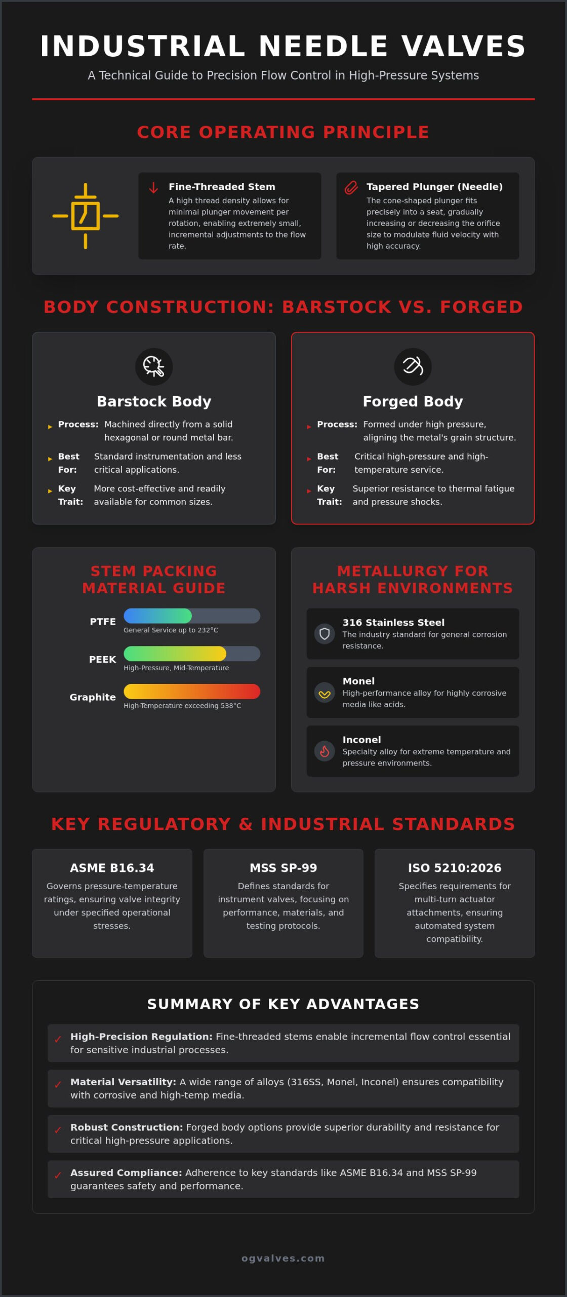
The needle valve is a precision flow-control instrument engineered for high-pressure industrial systems where incremental regulation is a prerequisite for operational safety. Unlike quarter-turn ball valves or linear gate valves designed primarily for isolation, industrial needle valves utilize a multi-turn mechanism to achieve high-resolution throttling. This design incorporates a tapered, needle-like plunger that fits precisely into a matching seat to modulate fluid velocity with extreme accuracy. The primary mechanical advantage of this configuration lies in the fine-threaded stem. This high thread density allows for minimal longitudinal movement of the plunger per rotation. Consequently, operators can achieve flow regulation sensitivity that’s impossible with the coarse travel of standard isolation valves.
The engineering of the seat-to-plunger interface is vital for maintaining system integrity. Most high-specification models employ a metal-to-metal seal. This configuration ensures a high-integrity shutoff even in environments where soft seats would degrade due to thermal or chemical exposure. The precision of the machining on these components dictates the valve’s ability to prevent leakage at high differential pressures. For a basic overview of these components, a Needle valve typically consists of a small port and a threaded, needle-shaped plunger that allows for precise control of flow in systems requiring low flow rates.
The Tapered Plunger Mechanism
The relationship between the plunger taper angle and flow sensitivity is a fundamental design consideration. A shallower angle increases the stem travel required for a specific change in flow, providing superior resolution for critical applications. Many advanced industrial needle valves now feature a non-rotating stem design. This prevents the plunger from rotating against the seat during the final stages of closure, which significantly reduces galling and mechanical wear. This structural choice directly extends service life in high-cycle environments. Additionally, the port size must be balanced against the desired Flow Coefficient (Cv). Smaller ports offer better low-flow control but result in higher pressure drops across the valve body, a factor that must be calculated during the specification phase.
Stem Packing and Seal Integrity
Maintaining a pressure-tight seal around the stem is a common pain point in high-temperature service. Material selection for packing is dictated by the thermal and chemical profile of the media. PTFE is standard for general service up to 232°C, while Graphite is required for high-temperature applications exceeding 538°C. PEEK offers a reliable middle ground for high-pressure, mid-temperature requirements. For safety, a back-seating feature is essential. This design creates a secondary metal-to-metal seal when the valve is fully open, preventing stem blowout and allowing for packing adjustments while the system remains under pressure. For a broader look at regulatory requirements, see our Industrial Valves: The Engineer’s Comprehensive Guide to Selection and Standards (2026).
Classification by Configuration and Actuation
Selecting the appropriate configuration for industrial needle valves requires an evaluation of both the physical housing and the method of operation. Body construction typically falls into two categories: barstock and forged. Barstock valves are machined from solid hexagonal or round bars, providing a cost-effective solution for standard instrumentation. In contrast, forged bodies are manufactured through high-pressure forming processes that align the metal’s grain structure. This metallurgical alignment provides superior resistance to thermal fatigue and pressure shocks, making forged valves the preferred choice for critical high-pressure service. For projects requiring specific metallurgical integrity, procurement teams often rely on technical partners like OG VALVES LTD. to verify material certifications before deployment.
Beyond individual units, these valves are frequently integrated into multi-valve manifolds. Instrumentation loops in oil and gas refineries utilize 2-valve, 3-valve, or 5-valve manifolds to consolidate isolation, calibration, and vent functions into a single block. This integration reduces the number of potential leak points and simplifies the installation of pressure transmitters and gauges. The efficiency of the entire system depends on the synergy between the valve geometry and the surrounding piping architecture.
Inline vs. Angle Body Geometries
The flow path within the valve body dictates piping efficiency and system pressure drop. Inline (globe) designs are the standard for most process regulation tasks where a straight-through piping run is maintained. However, angle body designs offer a distinct mechanical advantage by facilitating a 90-degree turn within the valve itself. This eliminates the need for an additional elbow fitting, reducing the total component count and minimizing turbulent flow at the corner. These configurations are particularly effective in panel-mount applications for control room instrumentation. In specialized scientific fields, such as the use of Needle Valves in Gas Chromatography, the ability to mount these components securely to a bench or panel while maintaining precise flow control is critical for analytical accuracy.
Automated Needle Valve Actuation
While manual operation is sufficient for static calibration, modern industrial projects increasingly demand automated flow regulation. Pneumatic actuators are the primary choice for hazardous petrochemical zones due to their inherent explosion-proof characteristics and fail-safe capabilities. These units can be configured to close or open automatically upon loss of pilot air, protecting downstream equipment. Alternatively, electric actuators are specified for automated process loops where precise, repeatable positioning is required for SCADA integration. For a detailed analysis of these systems, refer to our Industrial Valve Actuators: A Technical Guide to Automation and Control. Transitioning from manual to automated control allows for real-time adjustments based on sensor feedback, significantly improving the stability of high-pressure process environments with industrial needle valves.
Material Selection and Pressure-Temperature Ratings
Material selection for industrial needle valves is the primary determinant of system longevity and safety in volatile process environments. While 316 Stainless Steel remains the industry standard due to its excellent mechanical properties and broad-spectrum corrosion resistance, high-pressure applications require rigorous metallurgical evaluation. Engineering for 6,000 PSI and 10,000 PSI service classes necessitates more than just increased wall thickness. It demands high-integrity alloys that maintain their structural soundness under extreme tensile stress. In these high-pressure tiers, the thread engagement and bonnet-to-body seal must be engineered to withstand mechanical forces that’d deform lower-grade materials.
When process media involve aggressive chemical agents, standard stainless steel isn’t always sufficient. Monel’s frequently specified for hydrofluoric acid or oxygen service, while Inconel and Hastelloy are required for extreme high-temperature or highly oxidizing environments. These alloys prevent premature failure in conditions that’d otherwise lead to rapid pitting or localized corrosion. Conversely, cryogenic service requires materials that retain ductility at sub-zero temperatures, preventing the brittle fractures that occur in many carbon steels.
Alloy Integrity in Corrosive Environments
In chloride-rich offshore environments, Stress Corrosion Cracking (SCC) is a significant risk for standard alloys. Specifying Duplex or Super Duplex materials can mitigate this, though 316 Stainless Steel is often sufficient if it’s properly passivated. For sour gas service containing hydrogen sulfide, adherence to NACE MR0175/ISO 15156 standards isn’t negotiable. These standards dictate hardness limits and heat treatment protocols to prevent sulfide stress cracking. While Carbon Steel (WCB) offers a cost-effective alternative for high-pressure isolation in non-corrosive utility lines, it doesn’t have the inherent resistance required for aggressive process loops.
Understanding Pressure-Temperature Curves
The performance of industrial needle valves is governed by the inverse relationship between operating temperature and maximum allowable working pressure (MAWP). ASME B16.34 provides the definitive framework for these ratings, categorizing materials into specific groups to define their safe operating envelopes. As temperatures rise, the material’s yield strength decreases, necessitating a de-rating of the valve’s pressure capacity. It’s critical to evaluate not just the metal body, but also the thermal limits of seats and seals. A valve rated for 10,000 PSI at ambient temperature might only support a fraction of that pressure at 400°C, particularly if soft-seated components are used.
Industrial Standards and Regulatory Compliance
Regulatory compliance in the manufacturing of industrial needle valves is the primary mechanism for mitigating operational risk in high-pressure systems. MSS SP-99 serves as the fundamental standard for instrument-grade valves, defining the design and testing parameters specifically for small-bore regulation components. Unlike general-purpose valves, components adhering to MSS SP-99 undergo rigorous pressure testing to ensure seat integrity and shell soundness. Complementing this, ASME B16.34 dictates the minimum wall thickness and pressure-temperature ratings based on material classification. Adherence to these benchmarks ensures that a valve specified for high-pressure service won’t suffer from structural deformation or catastrophic failure under load.
For applications involving flammable media, fire-safe certification according to API 607 or ISO 10497 is required. These standards evaluate the valve’s ability to maintain a seal during and after exposure to high-intensity thermal events. Beyond performance testing, 100% component traceability is mandatory in heavy industrial sectors. Material Test Reports (MTRs) provide the documented proof of chemical composition and mechanical properties, ensuring that the alloy delivered matches the engineering specification. This documentation is vital for maintaining the safety of critical infrastructure and ensuring compliance with global insurance and safety audits.
Adherence to ASME and MSS Benchmarks
Technical requirements for pressure testing protocols are split into shell and seat evaluations. The shell test verifies the pressure-retaining capability of the body, while the seat test confirms zero-leakage performance across the plunger interface. In gas systems, fugitive emission standards like ISO 15848 are increasingly prioritized to meet environmental mandates. These protocols quantify the leakage rate of the stem seal, ensuring long-term containment of volatile organic compounds. For a technical comparison of related components, review our guide on Understanding Industrial Check Valves: Design, Function, and Critical Selection (2026).
Certification for Hazardous Environments
Actuated industrial needle valves operating in explosive atmospheres must hold ATEX or IECEx certifications. These verify that the electrical or pneumatic components won’t act as an ignition source. In upstream oil and gas infrastructure, NACE MR0175 compliance is essential for preventing hydrogen-induced cracking in sour environments. Procurement specialists must distinguish between EN 10204 Type 3.1 and Type 3.2 certifications. While Type 3.1 is issued by the manufacturer’s authorized representative, Type 3.2 requires independent third-party verification, providing the highest level of assurance for critical infrastructure projects. To ensure your project meets these rigorous benchmarks, you can view our certified valve inventory.
Procurement Excellence and Quality Control Protocols
Securing industrial needle valves for critical infrastructure requires a transition from commodity-based purchasing to technical procurement excellence. Even a valve that meets all ASME B16.34 wall thickness requirements on paper can fail in the field if the delivered metallurgy doesn’t match the engineering specification. For procurement specialists in heavy industrial sectors, the focus must remain on material traceability and the verification of structural soundness. This process ensures that the precision flow control capabilities established during the design phase are maintained through the entire lifecycle of the component.
High-stakes environments, particularly in the offshore oil and gas or chemical processing sectors, demand a procurement partner that acts as a technical extension of the engineering team. This involves more than just fulfilling an order; it requires the provision of comprehensive documentation packages, including Material Test Reports and pressure testing certifications. By anchoring procurement in rigorous quality control, organizations can mitigate the risk of unplanned facility downtime caused by the installation of non-compliant components.
Positive Material Identification (PMI) Verification
The necessity of X-ray Fluorescence (XRF) or Optical Emission Spectroscopy (OES) testing for high-specification alloy valves is non-negotiable. PMI testing provides a non-destructive method to verify that the chemical composition of the valve body and stem matches the intended alloy. This step is vital for preventing material failure in corrosive or high-pressure loops where the wrong grade of stainless steel could lead to rapid pitting or stress corrosion cracking. Integrating PMI data into the final technical documentation package ensures 100% component traceability, providing a verifiable audit trail for safety inspectors and regulatory bodies.
Fast-Track Logistics and Global Supply
Managing the supply chain for international projects involves overcoming significant logistical hurdles, especially when delivering to remote sites. Strategic inventory management is the primary tool for reducing lead times on non-standard industrial needle valves made from exotic alloys. OG VALVES LTD. maintains an extensive stock of high-specification components, enabling rapid response to urgent project demands. This capability is paired with global fast-track delivery protocols designed to minimize the impact of component failure on operational output.
While needle valves are essential for fine regulation, many process systems also rely on robust isolation valves to manage larger flow volumes. For a clinical analysis of these components, see our Industrial Ball Valves: A Technical Engineering & Specification Guide. Combining technical expertise in material testing with a dependable global logistics network allows project managers to secure the high-integrity components necessary for safe and efficient industrial operations.
Securing System Integrity through Technical Specification
Achieving zero-leakage performance in high-pressure process loops requires a methodical approach to component selection. As established in this analysis, the efficacy of industrial needle valves depends on the clinical alignment of plunger geometry, metallurgical integrity, and adherence to ASME B16.34 and MSS SP-99 standards. Relying on baseline certifications isn’t sufficient for critical infrastructure; instead, engineers must prioritize documented material verification and rigorous pressure testing to prevent catastrophic failure in volatile environments.
Operational reliability is maintained through the synergy of technical expertise and logistical precision. By integrating in-house PMI testing and material verification protocols, project managers can ensure that every installed component meets the exact hardness and chemical composition requirements for its specific environment. We maintain an extensive stock of high-specification API and ASME compliant valves to support your most demanding infrastructure requirements. Contact OG VALVES LTD. for technical support and fast-track needle valve procurement. Our global logistics expertise ensures your facility maintains operational continuity without the risk of non-compliant component failure. We look forward to supporting your next critical project.
Frequently Asked Questions
What is the primary difference between a needle valve and a globe valve?
The primary difference lies in the resolution of flow control and the geometry of the closure element. While both utilize a rising stem design, industrial needle valves incorporate a slender, tapered plunger that allows for incremental flow adjustments in small-bore systems. Globe valves are generally intended for higher flow volumes where such extreme precision isn’t required for system stability.
Can needle valves be used for high-pressure steam applications?
Needle valves are suitable for high-pressure steam provided the specification includes high-temperature packing materials like Graphite. Standard PTFE seals will degrade rapidly at steam temperatures. It’s essential to verify that the body material and pressure-temperature ratings comply with ASME B16.34 Group 2.2 or higher to ensure the component maintains its structural ductility under thermal load.
What are the most common causes of needle valve failure in heavy industry?
Failure typically results from stem packing degradation or seat galling. In high-pressure service, improper packing maintenance leads to fugitive emissions and pressure loss. Seat galling occurs when a rotating plunger grinds against the seat during closure, creating microscopic leak paths. Particulate contamination also causes erosion of the needle tip, which prevents the valve from achieving a bubble-tight shutoff.
How do I calculate the flow coefficient (Cv) for a needle valve?
The Flow Coefficient is calculated using the formula Cv = Q * sqrt(SG / ΔP), where Q is the flow rate, SG is the specific gravity of the media, and ΔP is the pressure drop across the valve. Because industrial needle valves are throttling instruments, manufacturers provide Cv tables mapped to the number of stem turns. This allows engineers to select a valve that operates within its most linear control range.
Are needle valves suitable for handling slurries or media with solids?
Needle valves are not recommended for slurries or any media containing suspended solids. The narrow flow path and tight tolerances of the seat-to-plunger interface are highly susceptible to clogging and abrasive erosion. In these environments, solids will quickly damage the needle tip and prevent proper seating. For media with particulates, ball valves or specialized slurry valves are more appropriate selections.
What industrial standards govern the testing of needle valves?
Testing is primarily governed by MSS SP-99, which defines the design and performance requirements for instrument-grade valves. Manufacturers also reference API 598 for pressure testing protocols and ASME B16.34 for body integrity and wall thickness. These standards ensure that the valve can withstand its rated pressure without shell deformation or seat leakage in critical infrastructure applications.
When should I specify a non-rotating stem needle valve?
Specify a non-rotating stem for high-cycle applications or when utilizing soft-seated configurations. This design allows the plunger to move linearly into the seat without a twisting motion. By eliminating the friction associated with standard rotating stems, you prevent galling and significantly extend the service life of the seat. This is a critical requirement for maintaining seal integrity over thousands of operational cycles.
What is the maximum pressure rating typically available for industrial needle valves?
Most standard units are rated for 6,000 PSI or 10,000 PSI service classes. Specialized forged-body valves are available for extreme applications reaching 15,000 PSI or higher, such as chemical injection systems. These maximum ratings are always subject to temperature de-rating according to ASME B16.34 tables, meaning the allowable pressure decreases as the operating temperature of the process media increases.
 Responsive Menu