A single undocumented deviation in a high-pressure valve casting can result in catastrophic mechanical failure, leading to significant financial loss and environmental hazards. Engineering teams often encounter technical ambiguity when reconciling international standards, which increases the risk of structural compromise in high-stress environments. Establishing a rigorous industrial valve inspection and testing plan is not a secondary administrative task; it’s a fundamental requirement for operational safety and strict regulatory adherence.
You recognize that clinical precision in quality control is the only method to ensure long-term asset integrity. This article provides a comprehensive roadmap to master the valve inspection framework, allowing you to secure zero-failure performance across your infrastructure. We will analyze critical hold points, material verification protocols under MSS-SP-55, and the latest pressure testing requirements defined by the API 598 11th Edition and ASME B16.5 2025 standards. This technical guide outlines the necessary verification steps for Gate, Ball, Globe, and Check valves to ensure your procurement meets the highest engineering benchmarks.
Key Takeaways
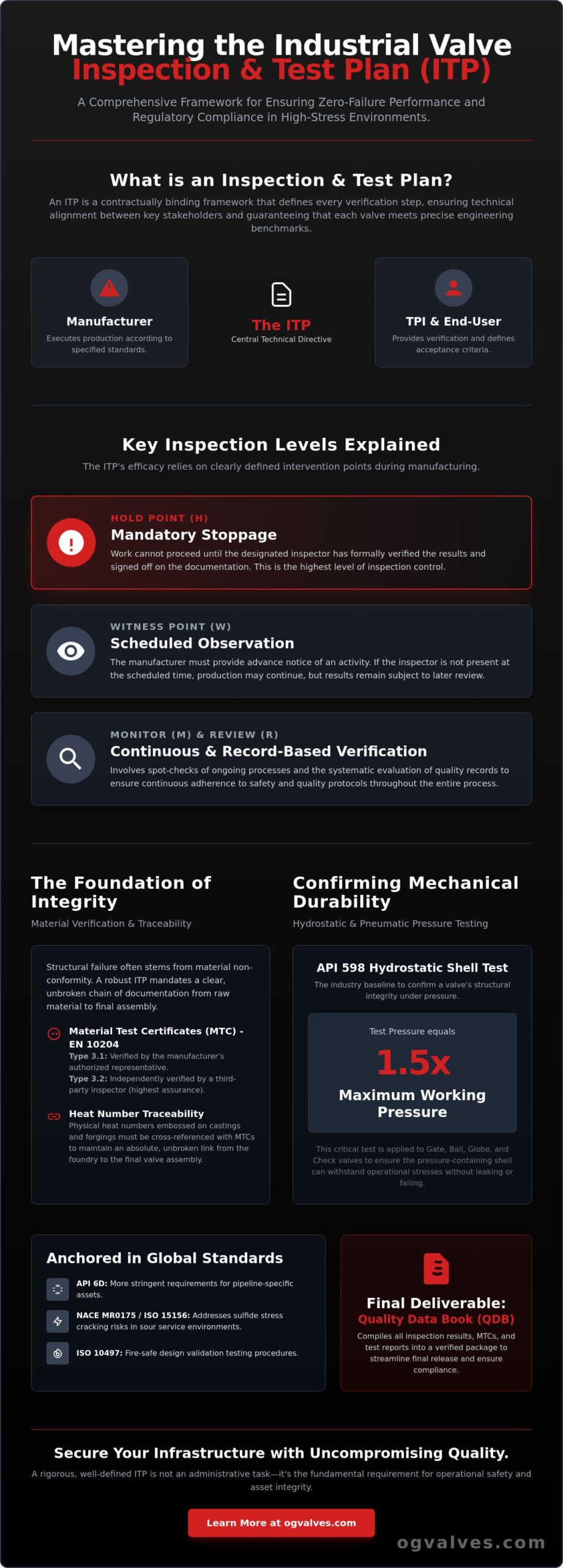
- Define the essential components of a robust industrial valve inspection and testing plan to ensure technical alignment between manufacturers, third-party inspectors, and end-users.
- Secure structural integrity by validating Material Test Certificates against EN 10204 standards for all pressure-containing components.
- Execute standardized hydrostatic shell tests at 1.5 times the maximum working pressure to confirm the mechanical durability of gate, ball, and check valves.
- Compile all inspection results into a verified Quality Data Book to streamline final release and ensure compliance with global safety regulations.
Fundamentals of a Valve Inspection and Test Plan (ITP)
An industrial valve inspection and testing plan (ITP) serves as the primary technical directive for the procurement of high-specification flow control assets. It isn’t a generic quality checklist but a structured, contractually binding framework that defines every verification step from raw material procurement to final certification. For critical infrastructure projects, the ITP ensures that each gate valve, ball valve, or check valve meets the precise mechanical and chemical properties required for high-pressure service. This document facilitates technical alignment between three primary stakeholders: the manufacturer, who executes the production; the Third-Party Inspector (TPI), who provides independent verification; and the end-user, who defines the acceptance criteria.
While a Quality Management System (QMS) provides the broad organizational standards for a facility, the ITP is a granular, project-specific document. It translates high-level engineering requirements from ASME B16.34 and API standards into actionable inspection steps. This level of detail is necessary to mitigate the risk of material failure in volatile environments. Without a finalized industrial valve inspection and testing plan, the path to regulatory compliance remains ambiguous, often leading to costly documentation delays or technical non-conformities during final handover.
Defining Hold, Witness, and Monitor Points
The efficacy of an ITP relies on the clear definition of inspection levels. A Hold Point (H) represents a mandatory stoppage in the manufacturing sequence. Work cannot proceed beyond this stage until the designated inspector has verified the results and signed off on the documentation. Witness Points (W) require the manufacturer to provide advance notice of an activity. If the inspector isn’t present at the scheduled time, production may continue, though the results remain subject to later review. Monitor Points (M) and Review Points (R) involve spot-checks of ongoing processes and the systematic evaluation of quality records, such as Partial Stroke Testing (PST) data for automated valve assemblies, to ensure continuous adherence to safety protocols.
The Role of International Standards in ITP Development
Technical excellence in valve manufacturing is anchored in global benchmarks. API 598 remains the industry baseline for the inspection and testing of most industrial valves, including globe and butterfly configurations. For pipeline-specific assets, API 6D introduces more stringent requirements for seat leakage and cavity relief. When valves are destined for sour service, the ITP must integrate NACE MR0175/ISO 15156 to address sulfide stress cracking risks. Fire-safe designs require validation through ISO 10497. These standards aren’t optional suggestions; they’re the clinical metrics used to verify that an asset can withstand the operational stresses of heavy industrial applications.
Material Verification and Traceability Requirements
Structural failure in high-pressure systems often stems from material non-conformity. Raw material validation establishes the foundation of valve integrity within any industrial valve inspection and testing plan. Every pressure-containing component, including the body, bonnet, and stem, requires comprehensive verification to ensure chemical and mechanical properties align with the design specification. This process begins with the examination of Material Test Certificates (MTC) according to EN 10204 standards. A 3.1 certificate provides validation by the manufacturer’s authorized representative; however, a 3.2 certificate requires independent verification by a third-party inspector or an end-user representative. This documentation must be cross-referenced with the physical heat numbers embossed on the castings or forgings to maintain absolute traceability from the foundry to the final assembly.
The technical necessity of traceability extends beyond mere record-keeping. It’s a safeguard against the accidental introduction of sub-standard materials into the production line. Similar to the protocols found in a comprehensive Inspection and Test Plan (ITP) for Control Valves, the documentation must reflect the exact metallurgical composition of the batch. If a heat number is lost during machining, the component is effectively disqualified from high-specification service. Maintaining this link is critical for ensuring that the finished product can withstand the calculated operational stresses without premature fatigue or rupture.
Casting and Forging Inspection Protocols
Visual inspection standards for surface defects must adhere to MSS SP-55. This standard defines the acceptance criteria for various surface irregularities, ensuring that castings are free from cracks, hot tears, and shrinkage. Inspectors verify chemical composition and mechanical properties, such as tensile strength and elongation, against specific ASTM specifications like A216 for carbon steel or A351 for stainless steel. For industrial gate valves in high-pressure service, these protocols are mandatory to prevent localized stress concentrations that could lead to casing failure under load.
Advanced Material Testing: PMI and Hardness
Positive Material Identification (PMI) is a critical non-destructive requirement for high-alloy and duplex steels. Using X-ray Fluorescence (XRF) technology, technicians verify the elemental composition of the alloy without damaging the component. This step prevents material mix-ups that could compromise corrosion resistance. Hardness testing is equally vital for valves intended for sour gas or corrosive environments, where exceeding specific Brinell or Rockwell limits increases the risk of hydrogen-induced cracking. Ensuring material compliance for specialized industrial ball valves in chemical processing protects the asset against aggressive media. If you require components that meet these rigorous metallurgical standards, you can evaluate our technical specifications for heavy-duty industrial applications.
Non-Destructive Testing (NDT) and In-Process Inspections
Non-destructive testing (NDT) serves as the clinical verification phase within an industrial valve inspection and testing plan. While material certificates provide historical validation, NDT identifies physical discontinuities in the present state of the component. These methods are categorized into volumetric and surface inspections, each targeting specific defect types that could compromise pressure containment. Acceptance criteria for these tests must strictly follow ASME Section V and Section VIII standards to ensure engineering excellence and operational safety.
Establishing a comprehensive Valve Inspection and Test Plan requires selecting NDT methods based on the specific manufacturing process. Castings typically demand different volumetric protocols than forged bodies. Surface integrity is equally vital; even minor linear indications can propagate into major cracks when subjected to thermal cycling or high-velocity flow. Precision in these inspections prevents the deployment of defective assets into critical infrastructure where the cost of failure is absolute.
Volumetric vs. Surface Inspection Methods
- Radiographic Testing (RT): Technicians utilize ionizing radiation to detect internal voids, shrinkage, or gas inclusions. It’s standard practice to mandate RT for high-pressure check valves where internal casting quality is paramount for seat integrity and long-term durability.
- Ultrasonic Testing (UT): High-frequency sound waves provide an effective alternative for forged components and thick-walled sections where RT sensitivity might be limited. UT is highly efficient for determining precise wall thickness and detecting laminar defects.
- Magnetic Particle Testing (MT): This method identifies surface and near-surface flaws in ferromagnetic materials by inducing a magnetic field. It’s essential for inspecting weld prep areas and highly stressed transitions in carbon steel components.
- Dye Penetrant Testing (PT): For non-ferromagnetic alloys, PT reveals surface-breaking cracks through capillary action. It’s a mandatory requirement for stainless steel and duplex components to ensure surface soundness.
Dimensional Control and Visual Examination
Dimensional verification ensures that the valve integrates into the piping system without inducing mechanical stress. Inspectors verify face-to-face and end-to-end dimensions against the approved General Arrangement (GA) drawings and ASME B16.10 2022 standards. This step’s non-negotiable for ensuring installation interchangeability across global supply chains. Visual examination focuses on flange serrations and gasket contact surfaces, which must be free from scratches or dents that could cause external leakage. Finally, wall thickness is measured at multiple points to confirm compliance with the minimum requirements of ASME B16.34, ensuring the pressure-retaining envelope can withstand the specified design pressure without deformation.
Hydrostatic and Pneumatic Pressure Testing Procedures
Pressure testing represents the final mechanical validation within an industrial valve inspection and testing plan. It’s the physical proof that the pressure-retaining envelope and sealing interfaces can withstand operational loads without compromise. This phase must follow a specific sequence to ensure that the primary structural integrity is verified before evaluating the seat’s sealing performance. Any failure during these procedures requires immediate rejection and a full root-cause analysis of the material or assembly process. Technical precision here is non-negotiable for assets destined for critical infrastructure.
The Shell Test is the primary method for validating the structural soundness of the valve body and bonnet. Per API 598 11th Edition and ASME B16.34, this test is conducted at 1.5 times the maximum working pressure at 100°F. The valve is partially open, and the ends are blinded, allowing the internal cavity to reach full test pressure. Following the shell verification, high-pressure closure (seat) tests and low-pressure gas tests are performed. While hydrostatic seat tests use liquid to verify sealing at high pressures, low-pressure pneumatic tests are more sensitive at detecting minute leak paths that liquid might bridge. For gate and globe valves, a backseat test is also required to ensure the stem seal can be isolated while the valve is in the fully open position.
Execution of the Valve Shell and Seat Tests
Execution begins with meticulous preparation of the test medium. For stainless steel or duplex components, the water’s chloride content must remain below 30ppm to prevent stress corrosion cracking. Testing durations are strictly governed by valve size and pressure class. According to API 598, a 2-inch valve shell test requires a minimum duration of 15 seconds, whereas a 12-inch valve demands at least 120 seconds of sustained pressure. Acceptance criteria are absolute for soft-seated valves, which require zero-leakage performance. Metal-seated valves, however, are evaluated against allowable leakage rates defined by the standard, typically measured in drops per minute or bubbles per minute for gas tests.
Functional and Operational Testing
Functional testing verifies that the valve operates within the specified torque limits under differential pressure. This is particularly critical for actuated valves, where the actuator must provide sufficient force to overcome seat friction and hydrodynamic loads. Inspectors verify the calibration of limit switches and the responsiveness of pneumatic or electric control systems. For ball and plug valves, anti-static testing is a mandatory safety requirement; it ensures electrical continuity between the stem, ball, and body to prevent static discharge in volatile environments. If your project requires verified performance under extreme pressures, you can review our technical testing protocols for high-specification industrial valves.
Final Inspection, Certification, and Quality Data Books (QDB)
The completion of physical testing doesn’t signal the end of technical oversight. Every verification point within the industrial valve inspection and testing plan must be formally closed before an asset is cleared for shipment. This final phase involves a clinical review of all preceding data points to ensure they align with the project’s engineering specifications. Once the manufacturer and the third-party inspector verify that all non-conformities are resolved, the valve moves into the final preservation and documentation stage. This process ensures that the technical integrity established during manufacturing is maintained throughout the global supply chain.
A finalized Release Note serves as the terminal gatekeeper. It’s a declarative statement that the product meets every requirement of the industrial valve inspection and testing plan. This document is essential for procurement specialists and site engineers, as it provides the necessary authorization to integrate the valve into critical infrastructure. Without this verified pedigree, the risk of installing an unvetted component remains unacceptably high in heavy industrial sectors.
Preservation, Packaging, and Marking
Proper preservation prevents environmental degradation during transit and long-term storage. SS316 stainless steel tags are mandatory; they’re permanently attached and must clearly display the heat number, tag number, and pressure rating class. Flange faces are highly vulnerable to mechanical damage, so high-density plastic caps or bolted wooden protectors are utilized for end protection. For valves destined for maritime or tropical environments, specialized corrosion-inhibiting coatings are applied to unpainted surfaces. Internal cleaning is equally critical; for example, valves designated for oxygen service require rigorous degreasing and specialized sealing to prevent combustion risks during operation.
Compiling the Quality Data Book (QDB)
The Quality Data Book (QDB) is the definitive technical dossier for each asset. It isn’t merely a collection of papers but a vital tool for life-cycle management and future industrial valve maintenance. A comprehensive QDB provides the traceability required for safety audits and operational troubleshooting. It must contain the following verified components:
- Approved Material Test Certificates (MTCs) for all pressure-containing parts.
- Non-Destructive Testing (NDT) reports and radiographic films.
- Hydrostatic and pneumatic pressure test certificates.
- Dimensional inspection reports and GA drawings.
- The final Certificate of Conformance (COC) signed by the quality manager.
This documentation package ensures that the end-user has a complete record of the valve’s manufacturing history. It establishes the clinical proof of durability and regulatory adherence required for high-pressure and high-temperature applications.
Securing Infrastructure through Technical Compliance
Implementing a rigorous industrial valve inspection and testing plan is the only viable method to mitigate the risks associated with high-pressure fluid control. Technical excellence depends on the clinical verification of material heat numbers, the execution of volumetric NDT, and the strict adherence to API 598 pressure testing durations. These protocols ensure that every gate, ball, or check valve performs according to its engineering design. By consolidating all verification data into a verified Quality Data Book, you establish a permanent record of structural integrity and regulatory adherence.
Our organization acts as a dependable partner for large-scale industrial demands. We maintain an extensive stock of API and ASME compliant valves, supported by global logistics and fast-track delivery capabilities. Our team provides full technical support and comprehensive documentation management to streamline your procurement process. Request a Technical Quote for High-Specification Industrial Valves to ensure your critical infrastructure meets the highest global benchmarks. Professional precision is the foundation of operational safety.
Frequently Asked Questions
What is the primary difference between API 598 and API 6D testing?
The primary difference lies in the application and test duration. API 598 serves as the standard for general-purpose valves, but it’s not the correct choice for pipeline service. API 6D is strictly for pipeline valves and mandates longer pressure holding times. It includes specific functional tests for cavity relief and double block and bleed (DBB) capabilities that aren’t required by API 598. These additional requirements ensure pipeline integrity under varying operational conditions.
Why is a Low-Pressure Gas Test required if the Hydrostatic Test passed?
A low-pressure gas test is required because air or nitrogen has a significantly lower viscosity than water. While a hydrostatic test verifies structural integrity, it’s the gas test that identifies minute leak paths. Water can bridge small apertures due to surface tension, potentially masking a failure that a gas test would identify. This step is essential for ensuring seat integrity in gas service applications where even minor leaks are unacceptable.
What are the mandatory hold points in a standard valve ITP?
Standard hold points in an industrial valve inspection and testing plan typically include raw material verification, the hydrostatic shell test, and the final visual and dimensional examination. These stages require a mandatory stoppage of work until the authorized inspector provides a formal sign-off. Work cannot proceed to the next phase without this technical validation. This ensures that any non-conformity is identified before the asset reaches the final assembly stage.
How is chloride content managed during the hydrostatic testing of stainless steel valves?
Chloride content management is achieved by using demineralized or treated water for the test medium. For stainless steel and duplex alloys, the chloride concentration must remain below 30 ppm to prevent the risk of stress corrosion cracking. Technicians must verify and document the water quality through laboratory analysis before the testing sequence begins. This clinical focus on water chemistry protects the metallurgical integrity of high-alloy valve components during the testing phase.
What is the significance of an EN 10204 3.2 certificate over a 3.1 certificate?
An EN 10204 3.2 certificate requires independent verification by a third-party inspector or customer representative who must witness the material testing at the mill. In contrast, a 3.1 certificate is a self-declaration by the manufacturer’s authorized quality department. The 3.2 certification provides a higher level of technical assurance for critical, high-specification projects. It confirms that the material properties meet the design requirements through independent oversight and validation.
Can a valve be released if a witness point was missed by the TPI?
A valve can technically be released if a witness point was missed, provided the manufacturer gave the required notice and documented the results correctly. Unlike hold points, witness points don’t mandate a stoppage of work if the inspector is absent at the scheduled time. However, the manufacturer remains responsible for providing all quality records for subsequent review and approval. If the records are insufficient, the inspector may request a re-test.
What are the allowable leakage rates for metal-seated valves under API 598?
Under API 598, soft-seated valves must demonstrate zero-leakage performance during closure tests. For metal-seated valves, the standard defines allowable leakage rates based on the nominal valve size and the test medium. For example, a metal-seated check valve or gate valve up to 2 inches has a maximum allowable leakage of zero drops per minute for liquid. Larger valves permit specific leakage rates, typically measured in drops or bubbles per minute, according to size-based tables.
How does an ITP address the requirements for fire-safe testing?
An industrial valve inspection and testing plan addresses fire-safe requirements by referencing standards such as ISO 10497 or API 607. The ITP specifies the testing protocols where the valve is exposed to high temperatures to destroy primary soft seals, followed by a measurement of the secondary metal-to-metal seal performance. These results are recorded in the final Quality Data Book. This verification ensures that the valve maintains containment if it’s exposed to fire.
 Responsive Menu