Non-Slam Check Valves: Preventing Water Hammer in Critical Infrastructure
March 21, 2026
Home+Non-Slam Check Valves: Preventing Water Hammer in Critical Infrastructure
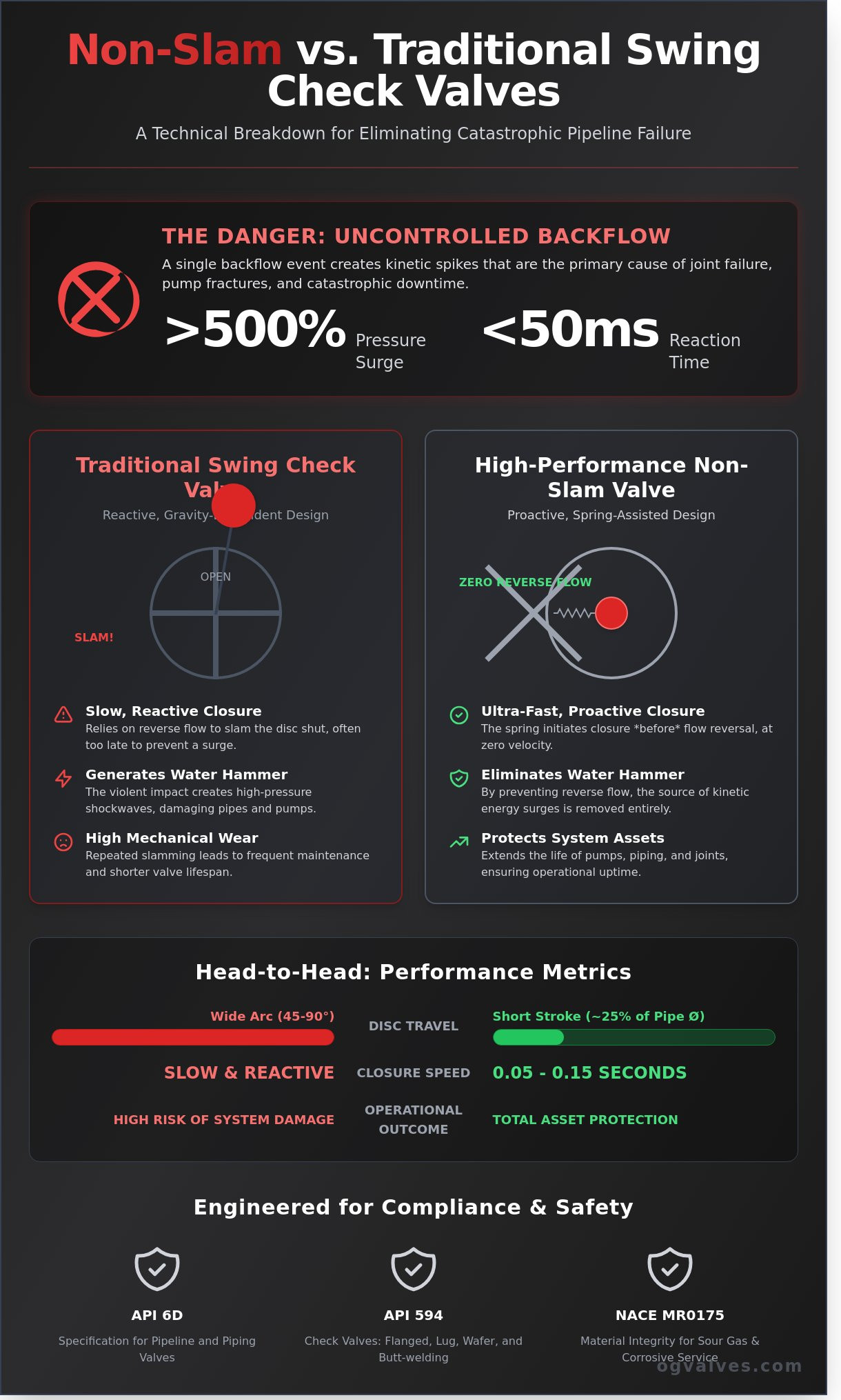
A single instance of uncontrolled backflow can generate pressure surges exceeding 500% of a pipeline’s rated operating pressure in less than 50 milliseconds. For facilities operating under API 6D standards, these kinetic spikes represent more than just a noise nuisance; they’re the primary catalyst for catastrophic joint failure and pump housing fractures. You understand that relying on conventional gravity-closed valves in high-velocity systems is a calculated risk that often results in unplanned downtime and expensive remediation. The mechanical limitations of traditional swing designs simply can’t match the deceleration rates required by modern industrial fluid dynamics.
This technical analysis provides a comprehensive deep-dive into the engineering and application of the non-slam check valve to eliminate pressure surges and protect high-value infrastructure. We’ll demonstrate how spring-assisted closure ensures the disc reaches its seat before flow reversal occurs, maintaining system integrity even during emergency shutdowns. This discussion covers precise sizing calculations, material specifications for corrosive service, and the rigorous testing protocols required to meet international safety certifications. We’ll conclude with a strategic framework for selecting valve architectures that guarantee 100% compliance with the industry’s most demanding safety standards.
Key Takeaways
Analyze the engineering principles of spring-assisted closure to effectively eliminate water hammer and pressure surges in high-pressure systems.
Compare the operational durability of nozzle-style designs against traditional swing check valves to reduce mechanical wear and extend maintenance intervals.
Identify critical international standards, including API 594 and NACE MR0175, required to ensure material integrity in sour gas and corrosive environments.
Implement precise sizing methodologies based on minimum flow velocity to avoid the common engineering pitfalls of line-size valve selection.
Discover how a high-performance non-slam check valve provides the rapid response necessary to protect downstream industrial assets from reverse-flow damage.
What is a Non-Slam Check Valve and How Does it Function?
A non-slam check valve is a precision-engineered axial flow or nozzle-style component designed to prevent backflow while eliminating the destructive pressure surges associated with valve closure. Unlike a standard Check valve, which may rely on gravity or the weight of a heavy flapper to seal, the non-slam variant utilizes a spring-assisted mechanism. This internal spring provides a constant force that acts on the disc, ensuring it remains in a state of readiness. As the forward flow velocity decreases to a predetermined threshold, the spring initiates the closing process before the fluid actually reverses direction. This proactive movement is the fundamental difference between a controlled industrial shut-off and a reactive, gravity-dependent failure point.
Traditional swing check valves are often ill-suited for high-velocity systems or vertical piping runs. In these older designs, the disc must travel through a wide arc, frequently 45 to 90 degrees, to reach the seated position. If the flow reverses before the disc seats, the fluid forces the disc to shut violently against the valve body. A non-slam check valve avoids this impact through a “Short Stroke” design. In this configuration, the disc travels a much shorter linear distance, often limited to 25% of the nominal pipe diameter. This reduced travel distance allows for closure speeds of 0.05 to 0.15 seconds, effectively sealing the orifice before the fluid column can gain reverse momentum.
Engineers should understand that the term “non-slam” is technically a misnomer for “zero reverse flow velocity” closure. The valve doesn’t just close softly; it closes at the exact moment the forward flow stops but before any backward flow begins. By achieving closure at the point of zero velocity, the valve prevents the sudden stoppage of a moving reverse fluid column. This technical precision protects downstream infrastructure, such as ASTM A216 WCB piping and high-value pumps, from the mechanical fatigue caused by repeated hydraulic shocks. It’s a clinical solution for systems where operational uptime and safety compliance are the highest priorities.
The Physics of Water Hammer and System Surges
Water hammer is a pressure surge caused by the momentum change of a fluid. When a fluid column in a high-pressure system is forced to stop or change direction abruptly, its kinetic energy converts into a high-pressure wave. These shock waves travel through steel piping at velocities exceeding 1,200 meters per second, creating localized pressures that can exceed five times the normal operating limit. A non-slam check valve mitigates these spikes by ensuring the system remains closed during the critical millisecond window when flow reversal would otherwise occur. Proper valve selection reduces the risk of pipe bursts and gasket failures in ASME Class 600 or Class 900 systems.
Dynamic Response: The Key Performance Metric
Dynamic response serves as the primary metric for evaluating valve efficiency in critical infrastructure. It’s measured in milliseconds and defines how quickly the internal disc reacts to changes in flow velocity. The spring constant, or K-factor, is the variable that determines the “pre-close” capability of the valve. A higher spring constant allows the valve to respond to rapid pump trips common in oil and gas midstream operations. Furthermore, the relationship between disc mass and acceleration is vital; a low-mass disc made from forged stainless steel can accelerate faster than a heavy cast iron flapper. This ensures the valve meets the rigorous performance standards required for cryogenic or high-temperature service.
Non-Slam vs. Traditional Swing Check Valves
Traditional swing check valves operate on a basic mechanical principle where a disc hangs from a hinge pin, relying on gravity and the force of reverse flow to shut. This design creates a significant lag during pump trips. In high-velocity systems, the fluid reverses direction almost instantaneously, often reaching high speeds before the disc makes contact with the seat. The resulting impact generates a high-pressure shockwave. A non-slam check valve, however, utilizes a spring-assisted disc that begins its closure stroke the moment forward flow decelerates. By the time the flow reaches zero velocity, the valve is already seated, effectively eliminating the kinetic energy that causes water hammer. Engineers seeking a deeper understanding of how does a check valve work across different non-return mechanisms will find that cracking pressure and reseat pressure dynamics are central to evaluating closure performance.
Closure speeds define the primary performance gap between these two technologies. While a standard swing valve might take 1.0 to 1.5 seconds to close, an axial-flow non-slam design typically completes its stroke in 0.05 to 0.15 seconds. This rapid response ensures that reverse flow velocity never reaches a critical state. To maintain system integrity, engineers must verify that these components adhere to the Process Valve Qualification Procedure, which establishes the testing benchmarks for valves used in volatile industrial environments.
The Failure of Swing Check Valves in High-Velocity Systems
In systems where pumps cycle frequently, swing check valves often fail due to disc chatter. This occurs when the flow velocity isn’t sufficient to hold the disc in a fully open, stable position. The constant oscillation causes severe mechanical wear on the hinge pin and bushings, leading to misalignment. A common misconception in the field is that a heavier disc provides a more secure seal. In reality, increased mass adds kinetic energy to the closure, which intensifies the slamming force and accelerates seat degradation. Heavier discs also require higher cracking pressures, which can lead to increased energy consumption across the pumping system. Engineers evaluating industrial check valves across dual-plate versus piston-lift configurations will find that design geometry plays a decisive role in preventing these failure modes. A detailed review of the swing vs lift check valve performance differences in high-pressure industrial applications further illustrates how disc geometry and orientation directly influence Delta P calculations and long-term seat integrity.
Operational Advantages of Nozzle and Axial Designs
Nozzle-style axial valves feature a streamlined internal flow path that significantly reduces turbulence compared to the bulky body of a swing valve. These designs often incorporate a Venturi effect through a contoured internal nozzle, allowing for excellent pressure recovery. This geometry ensures that the pressure drop across a non-slam check valve is often 20% to 30% lower than traditional alternatives in comparable service conditions. Their compact footprint and reduced weight, sometimes 40% lighter than swing valves, simplify installation in tight piping galleries.
Orientation Versatility: Unlike swing valves, which are largely limited to horizontal or vertical flow-up positions, axial non-slam valves function reliably in vertical flow-down configurations.
Pulsating Flow Tolerance: These valves are the standard for reciprocating compressor discharges where high-frequency pressure pulsations would destroy the hinge mechanism of a swing valve within weeks.
Maintenance Cycles: By eliminating the hinge pin and utilizing a short-stroke spring, axial valves reduce mechanical wear, often extending service intervals by 3 to 5 years in continuous-duty applications.
For facilities prioritizing long-term reliability and reduced downtime, selecting the correct internal geometry is a technical necessity. It’s vital to review technical specifications for axial check valves to ensure the chosen materials, such as forged steel or specialized alloys, meet the specific chemical and thermal demands of your process environment. Rigorous adherence to ASME and ISO standards during the selection phase prevents catastrophic surge events during emergency shutdowns.
Technical Specifications and Material Integrity
The structural integrity of a non-slam check valve depends on strict adherence to international engineering codes. Design parameters must align with API 594 for face-to-face dimensions and API 6D for pipeline service requirements. Pressure-temperature ratings follow ASME B16.34 standards, ensuring the pressure boundary remains intact across a range of industrial loads from Class 150 to Class 2500. For operations involving sour gas, NACE MR0175/ISO 15156 compliance is a mandatory requirement to prevent sulfide stress cracking in carbon and alloy steels. Engineers don’t overlook these specifications because they form the baseline for safety in high-pressure systems.
Material selection is dictated by the thermal and chemical profile of the media. Cryogenic processes operating at temperatures as low as -196°C require austenitic stainless steels or specialized nickel alloys to maintain notch toughness. Power generation environments exceeding 538°C demand chrome-moly steels like ASTM A217 Grade WC9 to resist creep and oxidation. Positive Material Identification (PMI) serves as a critical quality gate during procurement. Technicians use X-ray fluorescence (XRF) to verify that the alloy composition matches the Mill Test Report (MTR) with 100% accuracy. This process reduces the risk of material mix-ups by 98% in complex global supply chains.
Metallurgical Options for Corrosive Service
Offshore platforms and petrochemical facilities utilize Super Duplex and Monel to combat aggressive corrosion. Super Duplex stainless steel provides superior pitting resistance in chloride-rich environments, maintaining a Pitting Resistance Equivalent Number (PREN) above 40. For high-velocity flow areas, Stellite 6 hard-facing on seating surfaces increases hardness to approximately 40 to 45 HRC. This prevents erosion and extends the valve’s operational lifecycle in abrasive media. These metallurgical choices ensure the non-slam check valve performs reliably in the most punishing subsea and chemical processing environments.
Sealing Technologies: Metal-to-Metal vs. Resilient Seats
Engineers specify metal-seated valves for high-temperature durability where soft materials would degrade. These designs achieve API 598 leakage standards through precision lapping of the disc and seat. For applications requiring zero-leakage or bubble-tight shut-off, resilient seats utilizing Viton, EPDM, or PTFE inserts are integrated into the body. Fire-safe testing according to API 6FD ensures that the valve maintains its sealing integrity even after the primary soft seal is destroyed by extreme heat. This dual-sealing capability is vital for maintaining containment during emergency shutdown scenarios in refinery operations.
API 594: Standard for wafer, lug, and double-flange check valves.
ASME B16.34: Defines the pressure-temperature ratings for valve bodies.
NACE MR0175: Essential for preventing hydrogen-induced cracking in sour service.
PMI Testing: Verifies alloy chemistry to prevent catastrophic material failure.
Rigorous testing protocols, including hydrostatic and pneumatic shell tests, confirm the assembly’s integrity before site delivery. Every component must meet the specific project data sheet requirements to ensure long-term performance. It’s this level of technical precision that differentiates high-performance industrial valves from standard commercial hardware.
Selection and Sizing for Industrial Applications
Selecting a non-slam check valve based solely on nominal pipe size is a frequent engineering oversight that leads to premature mechanical failure. When a valve is oversized, the flow velocity is often insufficient to hold the disc in a stable, fully open position. This results in “disc flutter,” a condition where the internal components oscillate rapidly. This constant movement accelerates wear on the hinge pins and seats, often reducing the service life of the internal assembly by 60% compared to a correctly sized unit. Engineers must prioritize the minimum flow velocity (Vmin) required to achieve a full stroke of the disc. For most axial flow designs, maintaining a velocity between 2.5 and 4.0 meters per second is essential to ensure the disc remains tucked out of the flow stream, preventing turbulence and vibration.
Energy efficiency within the piping system is dictated by the valve’s cracking pressure and its flow coefficient (Cv). Cracking pressure represents the minimum upstream pressure required to initiate disc movement. If the spring tension is too high, it creates a permanent pressure drop that forces the pump to work harder, increasing energy consumption by as much as 3% to 5% in high-volume water transmission. Evaluating the Cv value allows designers to predict the exact pressure loss across the valve at peak flow. A higher Cv indicates lower resistance, which is vital for maintaining the required Net Positive Suction Head (NPSH) in pump suction lines. Data from field installations shows that optimizing Cv can reduce total head loss by 0.5 bar in Class 300 systems. A thorough review of how does a check valve work in relation to cracking pressure and API 6D compliance provides the mathematical foundation engineers need to optimize these parameters during the design phase.
Application-Specific Requirements
In desalination and water treatment facilities, pump discharge protection is critical. These systems require materials like Super Duplex or Nickel Aluminum Bronze to withstand corrosive media. In natural gas compressor stations, the non-slam check valve must respond within 0.5 seconds to prevent high-velocity backflow from damaging expensive turbine components during a surge event. Power plant boiler feed systems utilize these valves to manage thermal expansion backflow; failure to do so can lead to catastrophic pipe rupture due to pressure spikes exceeding ASME Section I limits.
A Checklist for Procurement Engineers
Procurement must verify that all technical specifications align with project-specific hydraulic data. It’s not enough to match the flange rating. Engineers should utilize the following checklist during the specification phase:
End Connections: Confirm compatibility with ASME B16.5 for Flanged, Wafer, or Lug designs, or ASME B16.25 for Butt-Weld requirements.
Fluid Dynamics: Account for fluid density and kinematic viscosity. High-viscosity fluids require adjusted spring rates to ensure the disc closes before the flow reverses.
Spring Range: Specify the spring tension based on the deceleration rate of the fluid column. A spring that’s too weak won’t close the valve fast enough to prevent a slam.
Certification: Ensure compliance with API 594 and ISO 9001 quality management standards.
Precision in sizing ensures that the valve functions as a safety device rather than a point of failure. Accurate calculations prevent the hydraulic shock that compromises the integrity of the entire infrastructure. Review our technical specifications for non-slam check valve engineering to ensure your system meets rigorous industrial standards.
OG Valves: Global Suppliers of High-Performance Check Valves
OG VALVES LTD. functions as a specialized procurement partner for high-pressure industrial environments. We source and supply every non-slam check valve to meet rigorous API 6D and ASME B16.34 standards. Our inventory management protocols ensure that every unit undergoes hydrostatic and pneumatic testing before dispatch to verify seat tightness. This clinical approach reduces the risk of field failure in critical pipelines where water hammer poses a threat. We’ve managed over 185 large-scale infrastructure projects across 42 countries, ensuring that engineering specifications align with functional reality.
Our commitment to technical support extends beyond simple distribution. We provide detailed QA/QC documentation for every order. This includes material test reports (MTRs) and pressure test certificates. We maintain a 99.7% quality pass rate across our entire supply chain. This reliability is why engineers in the oil, gas, and water treatment sectors trust us with their most demanding applications. We don’t just sell components; we provide the technical assurance required for long-term operational integrity.
Full compliance with ISO 9001:2015 quality management systems.
Rigorous verification of material grades including 316SS, Duplex, and Super Duplex.
Third-party inspection options (TPI) available for all critical service valves.
Fast-track logistics capable of reducing standard lead times by 25% for urgent site requirements.
The OG VALVES LTD. Advantage in Technical Procurement
Our Antrim-based engineering team coordinates logistics for global projects, spanning from desalination plants in the Middle East to petrochemical facilities in the Asia Pacific. We maintain a diverse stock profile including gate, globe, and specialized check valves. For those managing multi-valve specifications, our A Technical Guide to Industrial Gate Valves provides essential data on complementary flow control solutions. We prioritize material integrity; 98% of our stock carries full EN 10204 3.1 certification. This documentation is vital for compliance in high-risk sectors. Our team understands that downtime costs an average of $12,500 per hour in the oil and gas industry, which is why our response times are strictly monitored.
Requesting a Technical Specification for Your Project
Precision in valve selection requires comprehensive data. We analyze customer-provided data sheets to ensure accurate sizing and material compatibility. Our engineers evaluate flow velocity, pressure drop, and media viscosity to prevent cavitation and premature wear. We handle complex requirements involving exotic alloys or cryogenic service ratings. Every non-slam check valve we specify is selected based on its ability to meet the exact closing speed required for your specific piping geometry. This eliminates the guesswork that often leads to surge-related damage.
We invite procurement specialists to submit their technical requirements for a clinical review. Our process ensures that the final specification meets all international safety benchmarks and operational parameters. Contact OG VALVES LTD. for a technical consultation on your non-slam check valve requirements to secure the components necessary for your next critical infrastructure project. Our focus remains on durability, safety, and engineering excellence.
Optimizing System Integrity with Precision Flow Control
Ensuring the structural integrity of high-pressure fluid systems requires a proactive approach to surge mitigation. Integrating specialized valve technology into critical infrastructure effectively eliminates the risk of water hammer and subsequent pipe fatigue. OG Valves maintains an extensive inventory of API 594 and ISO 9001 compliant components designed for the oil, gas, and water treatment sectors. Our engineering team specializes in Super Duplex and high-alloy materials to ensure 100% resistance to corrosive media and extreme pressure cycles. We offer fast-track delivery globally to minimize project downtime and meet urgent maintenance schedules. Selecting the correct specification isn’t just a procurement task; it’s a commitment to long-term operational safety and system reliability. Our technical specialists provide the precise data and material certifications required for rigorous industrial compliance.
What is the primary difference between a slam and a non-slam check valve?
The primary difference lies in the closure mechanism and timing relative to flow reversal. A swing check valve relies on gravity or backflow to close the disc, which often results in a violent “slam” against the seat when the column reverses. In contrast, a non-slam check valve utilizes a spring-assisted mechanism to close the disc as flow velocity decelerates, ensuring the valve is fully seated before the fluid direction actually changes.
Can non-slam check valves be installed in vertical pipelines?
Yes, non-slam check valves are engineered for both horizontal and vertical pipeline orientations. Unlike traditional gravity-dependent valves, the internal spring provides the necessary force to return the disc to the seat. This design ensures the valve maintains its performance specifications in a vertical flow-up configuration, provided the system pressure exceeds the cracking pressure of the spring by at least 0.5 bar.
Do non-slam check valves increase the pressure drop in a system?
Non-slam check valves generally exhibit a higher pressure drop than full-port swing check valves due to the internal components located in the flow path. The presence of the spring, disc, and diffuser assembly restricts the flow area. Engineers should expect a 15% to 20% increase in head loss compared to a standard swing check, making it vital to calculate the Cv value during the system design phase.
Are non-slam check valves suitable for slurry or high-solids applications?
Standard non-slam check valves aren’t recommended for media containing solids exceeding 2% concentration. Particulate matter can accumulate in the spring mechanism or become trapped between the precision-machined seat and disc, leading to seal failure. For slurry service, engineers should specify specialized valves with protected springs or elastomer linings to ensure compliance with ISO 9001 durability standards.
How does a spring-assisted check valve prevent water hammer?
A non-slam check valve prevents water hammer by eliminating the sudden stoppage of a reversing fluid column. The spring forces the disc to close when the flow velocity drops toward zero, typically reaching the seat while the forward velocity is still 0.1 meters per second. This proactive closure prevents the kinetic energy of a returning fluid column from creating a pressure spike, which can exceed 500 psi in unprotected systems.
What maintenance is typically required for axial flow non-slam check valves?
Axial flow non-slam check valves require minimal maintenance because they lack external moving parts and packing glands. Industry data shows these valves often complete 1,000,000 cycles without requiring internal part replacement. We recommend an ultrasonic leak test every 24 months and a visual inspection of the spring tension during scheduled 5-year plant turnarounds to verify continued adherence to ASME B16.34 standards.
Is a non-slam check valve the same as a nozzle check valve?
The term nozzle check valve is a specific type of axial flow non-slam check valve. Both designs utilize a central shaft and a spring-loaded disc to achieve rapid, silent closure. These valves are the preferred choice for critical infrastructure because they reduce the potential for water hammer by 90% when compared to dual-plate or swing check alternatives in high-pressure gas or liquid systems.
What happens if a non-slam check valve is oversized for the flow rate?
If a non-slam check valve is oversized, the disc won’t reach its fully open, stable position during normal operation. This occurs when the flow velocity stays below the minimum 2.5 meters per second required to fully compress the spring. The resulting “disc flutter” causes the internal components to vibrate, which can lead to spring fatigue and seat erosion within 12 months of service.
 Responsive Menu