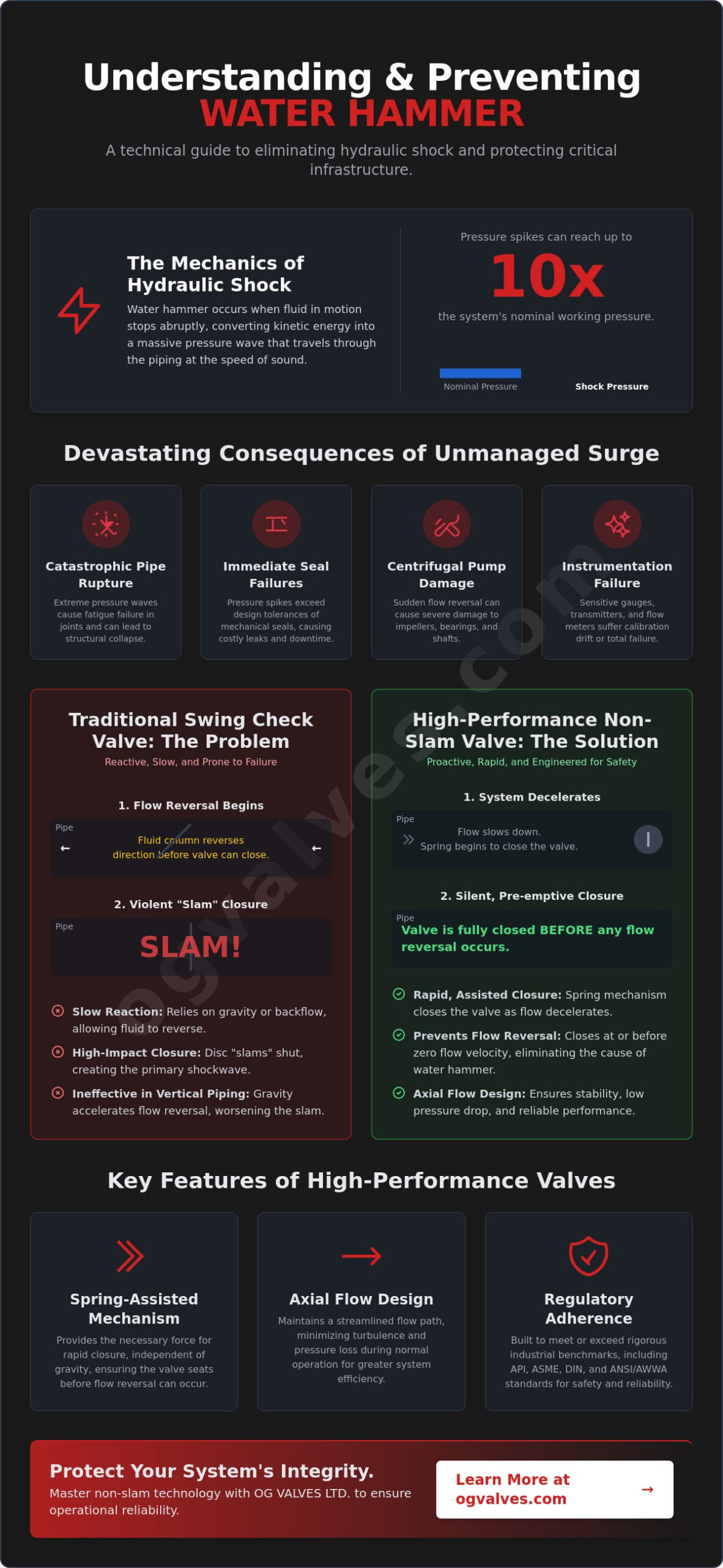
Water hammer isn’t an inevitable characteristic of high-velocity piping; it’s a measurable failure of valve closure synchronization with fluid deceleration. When a valve fails to react to flow reversal, pressure spikes can reach ten times the system’s nominal working pressure, leading to catastrophic pipe ruptures and immediate seal failures. Successfully preventing water hammer with check valves requires a shift from standard swing-check designs to high-performance, non-slam alternatives that prioritize rapid closure. This technical precision is essential for maintaining the structural soundness of critical industrial infrastructure.
You’ve likely dealt with the operational costs of vibration-induced equipment damage and the noise pollution inherent in poorly specified systems. This guide provides a technical framework for selecting valves that eliminate hydraulic shock while ensuring compliance with the updated ANSI/AWWA C508-25 standard for waterworks service. We’ll examine the engineering specifications of axial flow designs and provide the data necessary to extend system longevity and maintain rigorous industrial safety standards. By mastering non-slam technology, you ensure that your facility operates with the reliability and precision required in heavy industrial sectors.
Key Takeaways
- Understand the physical conversion of kinetic energy into pressure waves within rigid piping to identify high-risk zones for hydraulic shock.
- Analyze the mechanical limitations of swing check valves, specifically the closure lag that permits flow reversal and subsequent disc slamming.
- Learn technical strategies for preventing water hammer with check valves by implementing non-slam axial flow and spring-assisted closure mechanisms.
- Master the selection process by synchronizing valve closure speeds with system deceleration rates and calculating appropriate cracking pressures.
- Ensure long-term structural integrity and regulatory adherence by utilizing high-specification valves that meet API, ASME, and DIN benchmarks.
The Mechanics of Water Hammer and Hydraulic Shock
Water hammer is a kinetic energy conversion event that occurs when a fluid in motion is forced to stop or change direction abruptly. This sudden change in momentum creates a high-pressure shock wave that travels through the medium. The Mechanics of Water Hammer and Hydraulic Shock involve the propagation of these waves at the speed of sound, which is determined by the fluid’s bulk modulus and the pipe’s material properties. In rigid industrial piping, these waves reflect off bends, tees, and closed valves, creating a compounding effect that stresses the entire infrastructure.
It’s vital to distinguish between a standard pressure surge and true hydraulic shock. A surge is a relatively gradual change in pressure resulting from slow velocity adjustments. In contrast, hydraulic shock is an instantaneous event often triggered by rapid valve closure. This shock places extreme strain on critical system components, including:
- Centrifugal Pumps: Reverse flow can cause impeller damage and shaft misalignment.
- Mechanical Seals: Rapid pressure spikes exceed design tolerances, leading to immediate leakage.
- Instrumentation: Sensitive pressure transmitters and flow meters suffer calibration drift or total failure.
Engineers focused on preventing water hammer with check valves must recognize that these pressure spikes can reach ten times the system’s static working pressure. Without proper mitigation, the kinetic energy has no outlet, forcing the piping system to absorb the impact through elastic deformation or structural failure.
Calculating the Force of Hydraulic Shock
The intensity of the shock depends on fluid density, pipe elasticity, and the rate of velocity change. The Joukowsky Equation is the standard for estimating maximum surge pressure. It calculates the pressure change by multiplying fluid density by the wave speed and the change in fluid velocity. Because steel piping lacks the elasticity of thermoplastic materials, the resulting shock is significantly more severe in heavy industrial applications. Upon instantaneous valve closure, the fluid’s momentum is converted into a high-pressure pulse that can compromise even the most robust alloy systems.
Industrial Consequences of Unmanaged Surge
Uncontrolled hydraulic shock leads to fatigue failure in welded joints and flange connections. Over time, repeated pressure cycles weaken the structural integrity of the piping, resulting in costly downtime. In high-pressure oil and gas lines, the risk shifts from maintenance issues to catastrophic rupture. Preventing water hammer with check valves is a requirement for adhering to safety standards like ANSI/AWWA C508-25. Failure to contain these pressures can result in personal injury and significant regulatory penalties. Rigid adherence to engineering specifications ensures that system components remain within their designed elastic limits during transient events.
Check Valve Dynamics: Why Traditional Designs Fail
Traditional swing check valves are frequently misapplied in high-velocity industrial systems. Their reliance on gravity or backflow to initiate closure creates a fundamental mismatch with modern fluid dynamics. In systems where pumps trip or valves close elsewhere, fluid deceleration occurs rapidly. A swing check valve’s disc must travel through a wide arc to reach the seated position. This mechanical lag allows the fluid column to reverse direction and gain significant velocity before the valve closes. When the disc finally makes contact, it doesn’t just stop the flow; it creates a violent impact that generates pressure spikes.
Engineers tasked with preventing water hammer with check valves must understand that the “slam” is more than an audible nuisance. It represents a kinetic energy transfer that can exceed the yield strength of pipe materials. Gravity-assisted closure is particularly ineffective in vertical piping where the weight of the fluid column accelerates flow reversal, often outpacing the disc’s ability to seat. Without the assistance of a mechanical return, the disc remains suspended until the reverse flow force is high enough to drive it shut, ensuring a high-energy collision.
The Problem with Swing Check Valves
High-inertia discs in swing check valves are prone to delayed response times. The mass of the disc and arm requires substantial force to move, which isn’t always available during rapid flow cessation. Repetitive slamming leads to accelerated wear patterns on the hinge pin and seat, eventually compromising the valve’s ability to provide a bubble-tight seal. These designs are particularly unsuitable for pulsating flow environments, such as those found near reciprocating pumps, where constant disc oscillation causes premature mechanical failure and system-wide vibration.
Fluid Column Reversal and Valve Lag
The time gap between flow cessation and disc seating is a critical design variable. If the fluid reaches a “critical velocity” during reversal, the pressure spike upon closure is magnified exponentially. Technical documentation from the U.S. Army Corps of Engineers on Engineered Solutions: Non-Slam and Spring-Assisted Check Valves emphasizes the importance of modeling these transient events to avoid system rupture. When the reverse flow velocity is high, the seating force becomes destructive rather than functional. Selecting high-specification check valves with faster response times is the only reliable method for mitigating these dynamics in critical infrastructure. Preventing water hammer with check valves starts with acknowledging that traditional swing designs cannot meet the synchronization requirements of high-pressure industrial cycles.
Engineered Solutions: Non-Slam and Spring-Assisted Check Valves
Achieving total surge suppression requires a valve architecture that responds to flow deceleration in real-time. Axial flow or nozzle check valves represent the pinnacle of this engineering objective. Unlike the swing designs discussed previously, axial flow valves utilize a disc guided by a central shaft, moving along the longitudinal axis of the pipe. This streamlined annular flow path reduces turbulence and pressure drop while significantly shortening the disc’s travel distance. By minimizing the stroke length, the valve can reach its seat almost instantaneously as forward flow velocity approaches zero.
The implementation of these advanced geometries is the primary technical method for preventing water hammer with check valves in high-stakes industrial environments. These valves don’t rely on backflow to force the disc shut. Instead, they utilize a precisely calibrated internal spring to initiate closure. This proactive mechanical response ensures the disc is either seated or nearly seated before the fluid column can reverse direction. This eliminates the kinetic energy buildup associated with fluid column reversal, protecting downstream pumps and sensitive instrumentation from high-magnitude pressure pulses.
Material selection for internals is equally critical to ensuring the longevity of these solutions. High-durability alloys and specialized coatings are utilized for the disc, seat, and guide shaft to resist erosion and galling. In environments involving corrosive media or extreme temperatures, engineers often specify stainless steel or duplex internals to maintain structural soundness. The combination of optimized geometry and metallurgical precision results in a component capable of withstanding millions of cycles without compromising system safety.
Spring-Assisted Closure Mechanisms
Spring tension is the critical variable in achieving zero-lag closure. The spring rate must be high enough to overcome disc inertia and frictional resistance within the guide assembly, yet calibrated to ensure the valve opens fully at the system’s minimum operating flow. If the spring’s force is insufficient, the disc remains suspended during flow deceleration, allowing the reverse velocity window to open. Industrial experts must specify spring materials, such as Inconel or 316 stainless steel, to ensure long-term fatigue resistance. Regular inspection of these internal components is necessary to verify that spring force remains within the original design parameters.
Nozzle vs. Dual Plate Check Valves
While both nozzle and dual plate check valves offer improved performance over swing designs, their applications differ based on system requirements. Nozzle check valves feature a single, lightweight disc and a short-stroke spring, offering the fastest dynamic response and the lowest pressure drop. Dual plate valves utilize two spring-loaded semicircular plates. While dual plate designs are compact and effective for large-diameter liquid lines, the nozzle architecture is superior for gas compression and high-velocity liquid systems where preventing water hammer with check valves is a safety-critical requirement. The streamlined nozzle design minimizes the coefficient of discharge losses, making it the preferred choice for infrastructure where operational efficiency and surge protection are equally prioritized.
Selection Criteria for Preventing Surge in Industrial Systems
Engineering selection for preventing water hammer with check valves depends on synchronizing the valve’s dynamic response with the system’s deceleration profile. A mismatch here results in the destructive slam events discussed previously. Procurement specialists must prioritize adherence to API 594, which governs the design and performance requirements for check valves in high-pressure service. Compliance with ASME B16.34 is equally mandatory for establishing pressure-temperature ratings. These benchmarks ensure the valve body and internals maintain structural soundness under transient loads. Every component must be verified against these global standards to ensure long-term operational output.
Evaluating the pressure drop, or Delta P, against surge protection benefits is a critical trade-off in system design. While a higher spring rate improves closure speed, it also increases the cracking pressure required to initiate flow. Engineers must calculate the total energy loss across the valve to ensure the system remains efficient while providing adequate protection against hydraulic shock. Precision in these calculations prevents the common error of over-specifying spring tension, which can lead to unnecessary energy consumption and reduced flow capacity.
Critical Sizing and Flow Calculations
Proper sizing is more than matching the valve to the pipe diameter. Calculating the minimum flow required for full disc lift is essential to avoid disc chattering. Chattering occurs when the flow velocity is insufficient to hold the disc against its stop, leading to rapid oscillation and premature wear of the internals. Engineers utilize the flow coefficient, or Cv, to determine the pressure drop at specific flow rates. A valve with a high Cv value offers lower resistance, but the response time must still be fast enough to prevent flow reversal. In large-diameter systems, the relationship between pipe diameter and disc mass becomes a primary factor in determining the maximum allowable deceleration rate.
Environmental and Media Considerations
Material selection must be tailored to the specific chemical and thermal properties of the process media. In corrosive petrochemical environments, specifying duplex stainless steel or specialized alloy internals is necessary to prevent pitting and stress corrosion cracking. Power generation steam applications require high temperature ratings and materials that resist thermal fatigue. Consulting an industrial valves specialist for complex builds ensures that the chosen specification aligns with both environmental demands and safety regulations. You can view our comprehensive inventory of high-performance check valves to identify the exact material classifications required for your critical infrastructure. Precise metallurgical alignment is the final step in ensuring the reliability of surge mitigation strategies.
OG VALVES LTD. serves as a primary source for high-specification check valves engineered for the most demanding industrial applications. Our inventory is curated to meet the exact requirements of global infrastructure projects where the cost of failure is absolute. Every valve in our portfolio adheres to rigorous international standards, including API, ASME, and DIN. This commitment to regulatory adherence ensures that technical teams can specify our products with full confidence in their structural soundness and operational output. By providing components that meet these benchmarks, we assist technical experts in preventing water hammer with check valves across high-pressure systems.
Reliability isn’t a marketing claim; it’s a measurable outcome of engineering excellence. We understand that preventing water hammer with check valves requires more than just a standard component. It requires a partner who understands the physics of fluid deceleration and the necessity of zero-lag closure. Our technical team provides the data points necessary for complex builds, ensuring that the selected valve’s response time aligns perfectly with your system’s transient profile. This precision minimizes the risk of seal failures and pipe ruptures, extending the longevity of your facility’s critical assets. We don’t just supply hardware; we provide the technical foundation for system safety.
Global Supply Chain and Technical Expertise
Our global supply chain is optimized for the procurement of specialized alloys required for extreme industrial conditions. We source materials that resist erosion and thermal fatigue, ensuring that internals remain functional in corrosive petrochemical or high-temperature steam environments. Every valve undergoes rigorous quality control and testing protocols before reaching the site. Strategic logistics and project management capabilities allow OG VALVES LTD. to support international heavy industry sites with fast-track delivery schedules. This approach reduces the risk of costly downtime during maintenance or replacement cycles, providing a dependable link in your operational chain.
Procurement and Project Support
Procurement specialists face significant challenges when scheduling complex valve deliveries for large-scale projects. We provide assistance with detailed valve scheduling and specification to ensure that every component meets the project’s technical and regulatory demands. Whether you require a rapid response for a critical replacement or a comprehensive quote for a new build, our engineering team is prepared to provide detailed data and technical support. We focus on the functional reality of your system to ensure long-term performance. Contact our engineering team today for a technical quote and secure the high-performance components your infrastructure requires.
Securing Infrastructure with Advanced Surge Mitigation
Mastering the physics of fluid transients is the first step toward total system reliability. By transitioning from traditional swing designs to high-performance axial flow architectures, engineers address the root cause of hydraulic shock: closure lag. Effectively preventing water hammer with check valves depends on this precise mechanical synchronization. It’s essential to align valve response times with system deceleration rates to eliminate destructive pressure spikes and protect downstream instrumentation from catastrophic failure.
OG VALVES LTD. provides a comprehensive inventory of API 594 and ASME B16.34 compliant check valves, ensuring your infrastructure meets the highest safety benchmarks. Our team offers specialist technical support for heavy industry and maintains global fast-track delivery capabilities to support critical project timelines. You can rely on our expertise to source the exact material classifications required for extreme environmental conditions, ensuring that your procurement process aligns with rigorous engineering standards.
Protect your facility’s structural soundness and ensure unwavering operational output by selecting engineered solutions designed for durability. Request a Technical Quote for Industrial Check Valves to begin your specification process today.
Frequently Asked Questions
How do check valves prevent water hammer in industrial systems?
Check valves mitigate hydraulic shock by arresting flow reversal at the exact point of zero velocity. By utilizing a spring-assisted mechanism, these valves proactively seat the disc as forward momentum ceases. This synchronization is the primary technical method for preventing water hammer with check valves, as it stops the fluid column before it can gain the reverse kinetic energy that leads to destructive pressure spikes within the piping.
What is the difference between a standard check valve and a non-slam check valve?
A standard swing check valve features a high-inertia disc and a long travel arc, relying on gravity or backflow to close. This often results in a delayed response and a violent mechanical impact. In contrast, a non-slam valve uses a short-stroke, spring-assisted disc that reaches the seat before flow reversal occurs. This design eliminates the collision between the disc and the seat, ensuring a silent and shock-free closure.
Can a spring-loaded check valve be installed in vertical piping?
Spring-loaded check valves are the preferred solution for vertical-up flow applications. The internal spring provides a constant force that overcomes the weight of the fluid column, ensuring positive closure during pump shutdown. This prevents the fluid from accelerating backward under the force of gravity, which is a common cause of slamming in traditional gravity-dependent valves. It’s a reliable choice for maintaining system integrity in high-rise industrial configurations.
What are the most common causes of water hammer in pumping stations?
The most frequent causes include sudden pump trips, rapid valve closure, and power failures that disrupt flow stability. These events create an instantaneous drop in pressure, followed by a high-velocity return wave as the fluid column reverses direction. If the system’s check valves don’t close fast enough to meet this return wave, the resulting impact generates a pressure pulse that can exceed ten times the working pressure.
How does the Joukowsky Equation help in valve selection?
The Joukowsky Equation allows engineers to quantify the potential magnitude of a pressure surge based on fluid density, wave speed, and the change in velocity. By calculating this value, technical specialists can determine the maximum allowable closure time for a valve. This data is essential for preventing water hammer with check valves, as it ensures the selected component’s dynamic response is fast enough to keep transient pressures within safe limits.
Is a nozzle check valve more efficient than a swing check valve?
Nozzle check valves offer superior efficiency in high-velocity systems due to their streamlined annular flow path. This geometry significantly reduces turbulence and the resulting pressure drop compared to the obstructed flow path of a swing check. The nozzle design also features a much shorter stroke length, providing the rapid dynamic response required to protect critical infrastructure from the destructive forces of hydraulic shock and surge.
What industrial standards govern the design of non-slam check valves?
Several global benchmarks define the structural and operational requirements for these components. API 594 and ASME B16.34 are the primary standards for high-pressure industrial service. Additionally, the American Water Works Association recently updated its standard for iron-body swing-check valves to ANSI/AWWA C508-25, which applies to valves from 2-in. through 48-in. for waterworks service. Adherence to these standards ensures the valve can withstand transient pressure loads.
How do I calculate the required cracking pressure for my system?
To calculate cracking pressure, you must determine the minimum differential pressure required to overcome both the internal spring force and the weight of the disc assembly. This value must be high enough to ensure positive seating against the static head but low enough to allow the valve to open fully at the system’s minimum operating flow rate. Accurate calculation prevents disc chattering, which can lead to premature mechanical failure of the internals.
 Responsive Menu