How Does a Check Valve Work? A Technical Guide to Industrial Non-Return Mechanisms
March 23, 2026
Home+How Does a Check Valve Work? A Technical Guide to Industrial Non-Return Mechanisms
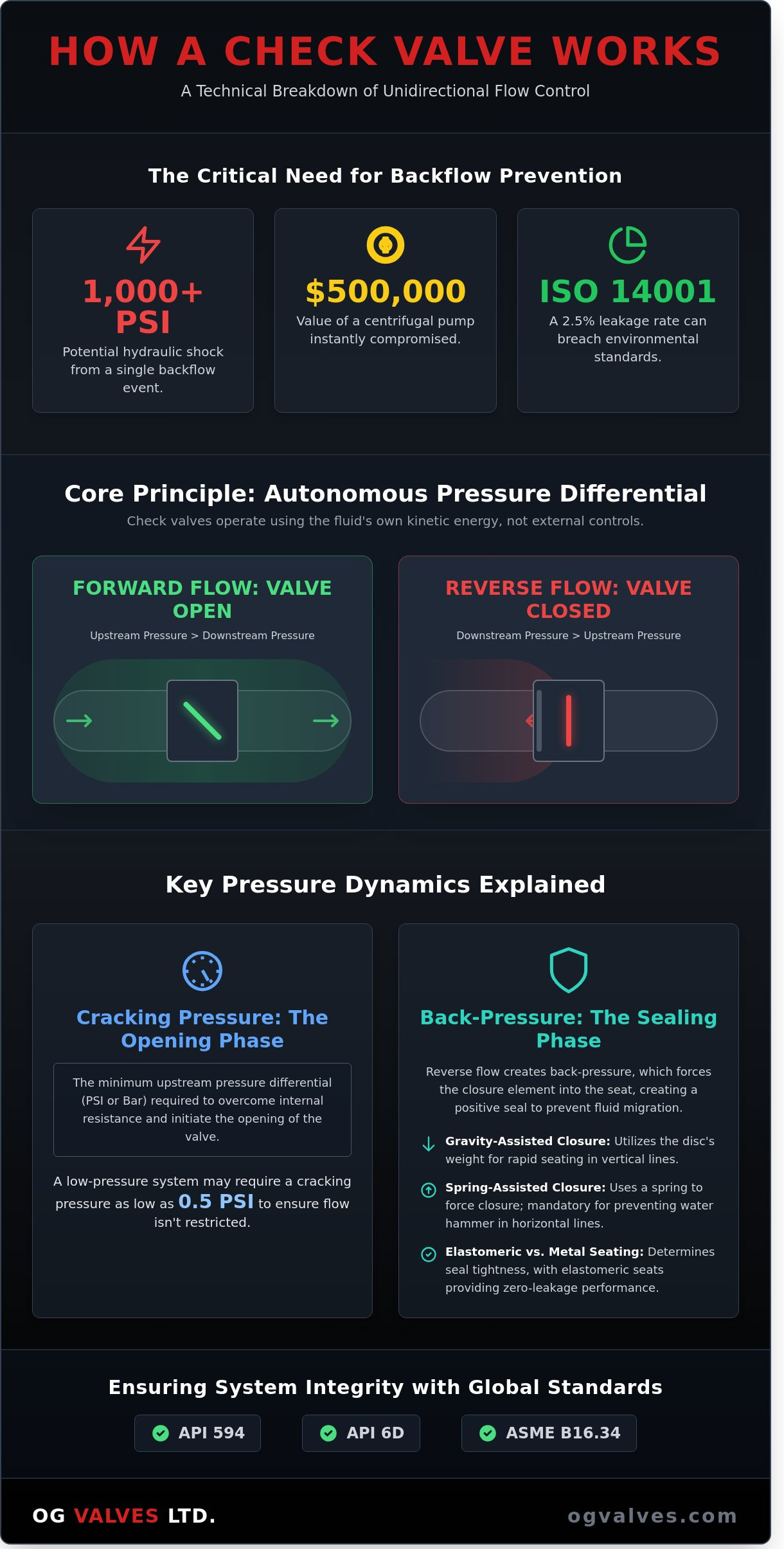
A single failure in backflow prevention can result in a hydraulic shock exceeding 1,000 PSI, instantly compromising the integrity of a $500,000 centrifugal pump. Engineers across the oil and gas sectors recognize that system reliability isn’t a matter of chance but a result of rigorous component selection. You’re likely aware that even a 2.5% leakage rate in a high-pressure line can lead to contamination levels that breach ISO 14001 environmental standards. Understanding exactly how does a check valve work is the first step in mitigating these operational risks.
This technical guide provides a clinical analysis of mechanical non-return principles, ensuring you can differentiate between cracking pressure and reseat pressure with mathematical certainty. We’ll examine the operational specifications of API 6D compliant valves and identify the optimal material grades for high-pressure service. By mastering these pressure dynamics, you’ll eliminate the variables that lead to water hammer and the 15% increase in maintenance costs associated with improper valve selection. We’ll conclude with a focus on ASME B16.34 standards to ensure your infrastructure meets global safety benchmarks.
Key Takeaways
Understand the fundamental mechanical principles of how does a check valve work by analyzing pressure differentials and self-actuating closure mechanisms required for unidirectional flow.
Evaluate the performance characteristics of swing, lift, and ball valve geometries to ensure precise alignment with specific fluid velocities and industrial viscosities.
Identify the engineering protocols required to mitigate water hammer and pressure surges, protecting critical infrastructure from catastrophic mechanical failure.
Assess the necessity of material integrity and compliance with international standards such as API 594 to guarantee rigorous safety and performance in high-pressure environments.
Develop a strategic procurement framework by prioritizing technical specialization and fast-track logistics to maintain long-term system integrity and operational reliability.
The Fundamental Mechanics of One-Way Flow Control
A Check valve is a self-actuating mechanical component designed to permit fluid or gas flow in a single direction while preventing reverse flow. It’s a non-return device that functions as a directional gatekeeper within a piping system. Understanding how does a check valve work requires an analysis of internal pressure dynamics rather than external control mechanisms. These components don’t rely on manual intervention, electrical actuators, or pneumatic signals; they use the kinetic energy of the media itself to trigger movement.
The operational logic is dictated by the pressure differential across the valve’s internal closure element. When the upstream pressure exceeds the downstream pressure plus the internal resistance of the valve, the disc or poppet moves to the open position. Conversely, when the flow velocity decreases or reverses, the valve closes. This autonomous functionality is a primary safety feature in industrial infrastructure. It ensures that system integrity is maintained even during total power loss or control system failure.
In high-stakes environments like oil refineries or municipal water treatment plants, the cost of backflow is substantial. A single reverse-flow event in a high-pressure pump system can lead to immediate impeller damage, costing a facility upwards of $85,000 in emergency repairs and unplanned downtime. By maintaining directional integrity, these components protect sensitive instrumentation and maintain system pressure according to API 594 and ASME B16.34 standards. They’re essential for preventing the contamination of clean media and protecting the mechanical lifespan of upstream hardware.
Cracking Pressure Dynamics: The Opening Phase
The transition from a closed to an open state depends on the cracking pressure. This is the specific pressure threshold required to overcome the internal resistance of the valve’s closure element. In a spring-loaded design, the spring rate determines this value. In a swing check valve, the mass of the disc and the angle of the seat are the primary variables. Engineers must specify cracking pressures that align with system pump curves to avoid premature wear. For example, a low-pressure system might require a cracking pressure as low as 0.5 PSI to ensure flow isn’t unnecessarily restricted.
Cracking pressure is defined as the minimum upstream pressure, quantified as a differential in PSI or Bar, required to overcome internal resistance and initiate the lift of the closure element from the seat.
The Role of Back-Pressure in Sealing Integrity
Sealing integrity depends on the accumulation of back-pressure. When downstream pressure exceeds upstream pressure, the fluid’s reverse force pushes the closure element back into the seat. This creates a positive seal that prevents fluid migration. The reseat pressure, often slightly lower than the cracking pressure, ensures the valve closes before backflow gains velocity. Mechanical variables influence this phase significantly:
Gravity-Assisted Closure: Utilizes the weight of the disc in vertical installations to ensure rapid seating.
Spring-Assisted Closure: Uses a mechanical spring to force the disc into the seat, which is mandatory for horizontal lines where 100% shut-off speed is required to prevent water hammer.
Elastomeric vs. Metal Seating: Determines the tightness of the seal, with elastomeric seats providing zero-leakage performance in gas applications.
The precision of the seal is vital for maintaining system prime. Without a reliable reseat, pumps may lose their suction head, leading to cavitation and eventual motor burnout. It’s the clinical interaction between these pressures that defines how does a check valve work in a continuous industrial cycle.
Mechanical Variations: How Different Check Valve Designs Operate
Understanding how does a check valve work requires a clinical analysis of internal closure geometry. Engineers select specific designs based on fluid velocity, media viscosity, and the physical orientation of the pipeline. A check valve’s primary function is the prevention of backflow, yet the mechanical execution of this task varies significantly between swing, lift, and ball configurations. Each design responds differently to the kinetic energy of the flow. For instance, a swing check valve utilizes a hinged disc that moves away from the seat during forward flow. This results in a full-port flow path with a pressure drop often measured at less than 0.5 PSI in standard water applications. If the system involves high-viscosity fluids or low flow velocities, the disc may not fully clear the flow stream, leading to premature seat wear.
Orientation dictates the mechanical success of these components. In horizontal lines, gravity assists the closure of a swing disc. Vertical installations are more complex. They require spring-assisted mechanisms to ensure the disc returns to the seat before flow reversal occurs. Without this precision, the system remains vulnerable to water hammer, which can generate pressure spikes exceeding 200% of the rated working pressure. Engineers seeking to optimize pipeline integrity can review our technical specifications for check valves to ensure compliance with API 6D standards.
Swing vs. Lift Check Mechanisms
Swing check valves are the industrial standard for large-diameter pipelines where flow resistance must be minimized. They’re effective in ASME Class 150 to 300 systems. Lift check valves operate differently, mirroring the internal configuration of a globe valve. The disc moves vertically, guided by a piston or stem. This design excels in high-pressure applications exceeding 2,500 PSI. While swing designs offer lower resistance, lift checks provide superior sealing integrity in high-pressure gas services. The trade-off involves mechanical wear; swing hinges are susceptible to pin erosion, whereas lift guides require rigorous lubrication and clean media to prevent sticking. For a detailed engineering breakdown of these performance trade-offs, our analysis of the swing vs lift check valve selection criteria for industrial applications provides the specific Delta P calculations and disc geometry data required for accurate specification.
Piston and Tilting Disc Operations
High-pressure steam and gas services often utilize piston check valves to handle flow pulsations. The piston moves within a dampened cylinder, which prevents the rapid chattering that destroys standard discs in turbulent environments. Tilting disc valves offer a different advantage. By using an offset pivot point, the disc opens fully at lower flow velocities. This geometry reduces energy loss by approximately 25% compared to conventional swing designs. Maintenance teams must prioritize the inspection of pivot pins in tilting discs, as these parts endure the highest mechanical stress during rapid cycling.
For installations where space is a primary constraint, the dual-plate wafer design is the standard technical solution. These valves use two spring-loaded plates hinged on a central pin. This configuration reduces the face-to-face dimension by up to 80% compared to traditional flanged swing checks. It’s a lightweight, robust method for backflow prevention in offshore platforms and refinery skids. By adhering to API 594 specifications, these valves maintain structural integrity while minimizing the total weight of the piping assembly. Every design choice, from the spring tension to the seat material, directly impacts how does a check valve work under extreme industrial loads. For a comprehensive review of dual-plate versus piston-lift configurations and their performance characteristics, see our detailed analysis of industrial check valves: design, function, and critical selection.
Mitigating Industrial Risks: Water Hammer and Surge Control
Hydraulic shock, technically identified as water hammer, represents one of the most significant threats to the structural integrity of high-pressure piping systems. This phenomenon occurs when the kinetic energy of a moving fluid column is abruptly converted into pressure energy. In a typical API 5L Grade B pipeline, a sudden velocity change of 1.5 meters per second can generate a pressure surge exceeding 50 bar above standard operating limits. If the check valve fails to close before the flow reverses, the resulting slam generates a shockwave that travels at sonic velocities through the medium. This often leads to catastrophic failure of flange gaskets, instrumentation, and pump casings.
Engineers shouldn’t assume that all check valves provide equivalent protection against these surges. A standard swing check valve relies on gravity and flow reversal to seat the disc. This inherent lag allows the fluid column to gain backward momentum. When the disc finally makes contact, the impact is violent. In the oil and gas sector, the cost of such failures is extreme. A 2022 analysis of midstream infrastructure incidents showed that surge-related ruptures resulted in an average of 48 hours of unplanned downtime, costing operators approximately $25,000 per hour in lost throughput. It’s essential for risk mitigation to understand how does a check valve work within the context of dynamic flow conditions.
Non-Slam Check Valve Engineering
Non-slam designs utilize a spring-assisted, short-stroke closure mechanism to prevent the disc from slamming against the seat. The internal spring is calibrated to overcome the inertia of the disc as soon as the forward flow velocity begins to decay. This ensures the valve is nearly seated before the fluid reaches a zero-velocity state. This design effectively decouples the mechanical closure from the fluid deceleration, preventing the pressure spikes associated with traditional tilting-disc valves. Non-slam check valves reduce noise and vibration in high-velocity lines by preventing the disc from oscillating against the internal stops during turbulent flow conditions. This precision engineering adheres to ASME B16.34 standards for pressure and temperature ratings, ensuring long-term reliability in critical service.
Cavitation and Turbulence Management
Internal erosion often stems from cavitation, a process where rapid pressure drops cause vapor bubbles to form and implode against the valve trim. These implosions generate localized micro-jets with enough force to deform hardened alloys. Technicians must monitor for specific physical indicators of degradation:
Surface Pitting: Small, localized craters on the disc face resembling sandblasting damage.
Orange Peel Texture: A distinctive roughness on 316 stainless steel or Stellite-faced components.
Seal Degradation: Loss of ISO 5208 leakage compliance due to seat deformation.
The relationship between the flow coefficient (Cv) and valve longevity is linear; a valve sized with an insufficient Cv for the application will experience increased turbulence and localized pressure drops. Selecting the correct trim material and disc geometry is vital to minimize internal erosion. Knowing how does a check valve work under variable load conditions allows procurement specialists to specify the correct materials for their specific industrial requirements, ensuring the valve maintains its sealing integrity over a 20-year service life.
Material Selection and International Regulatory Standards
Material integrity remains the primary differentiator in industrial procurement. While understanding how does a check valve work is fundamental, the operational lifespan depends entirely on metallurgical selection. Procurement teams prioritize materials that resist localized pitting and stress corrosion cracking. Failure to match the alloy to the medium results in catastrophic leaks, often costing upstream operators over $1.2 million per day in lost production. Engineers must adhere to API 594, which dictates the design and testing parameters for flanged, lug, wafer, and butt-welding configurations. This standard ensures interchangeability and safety across global infrastructure projects.
ASME B16.34 governs the pressure-temperature ratings for valve bodies. It defines the maximum allowable working pressure based on the material group and operating temperature. For instance, a Class 150 valve made of Group 1.1 carbon steel has a maximum working pressure of 285 psig at 100°F. If the process temperature rises to 500°F, the allowable pressure drops to 170 psig. It’s vital that specialists don’t overlook these gradients during the specification phase. Failure to account for these thermal shifts leads to rapid mechanical degradation of the valve housing.
In sour gas environments, compliance with NACE MR0175 is mandatory. This standard mitigates the risk of sulfide stress cracking caused by hydrogen sulfide (H2S). Materials must meet specific hardness limits, typically below 22 HRC for carbon steels, to prevent brittle failure in high-pressure gas lines. Every valve destined for these environments undergoes rigorous verification to ensure it meets the ISO 15156 requirements for oil and gas production.
High-Performance Alloys and Corrosive Service
Standard carbon steel fails quickly in aggressive media. Procurement specialists specify Super Duplex or Inconel 625 when chloride levels exceed 50,000 ppm. Stellite-faced seats, typically Grade 6 cobalt-based alloys, are utilized for high-temperature applications reaching 538°C. These overlays provide a surface hardness up to 45 HRC, resisting erosion from abrasive particulates. Every component requires material traceability. Mill Test Reports (MTRs) verify that the chemical composition and mechanical properties meet ASTM A216 or A351 requirements.
Testing and Quality Assurance Protocols
Rigorous testing ensures that the internal mechanism functions according to design specifications. Analyzing how does a check valve work under extreme pressure requires a look at API 598 testing protocols. The shell test requires 1.5 times the maximum design pressure for a duration of at least 60 seconds for valves under 2 inches. The seat leakage test utilizes 1.1 times the design pressure to confirm the seal’s integrity. Fugitive emission testing under ISO 15848-1 is now a standard requirement in petrochemical facilities to limit volatile organic compound leaks to less than 50 ppm. Engineers specifying check valves for high-pressure and corrosive service in 2026 should cross-reference these API 598 requirements against ASME B16.34 wall thickness mandates to ensure full compliance.
Procurement Strategy: Ensuring System Integrity with OG Valves
Procurement of critical flow control components requires more than a price-point comparison. Selecting a technical specialist over a general hardware vendor ensures that the fundamental operational logic of how does a check valve work aligns with the specific hydraulic pressures of your system. Generalists often overlook critical variables like cracking pressure, flow coefficient (Cv), or water hammer mitigation. OG VALVES LTD. provides engineering depth; we ensure every unit meets API 6D or ASME B16.34 standards before it reaches your site. Our engineers don’t just sell components; they interrogate your system data to prevent premature failure.
Technical expertise in valve sizing is the difference between a 20-year service life and a catastrophic failure within 6 months. We focus on metallurgical compliance, ensuring that material grades such as ASTM A216 WCB or A351 CF8M are correctly specified for your media. For high-pressure gas or corrosive chemical processing, we provide specialized alloys including Duplex and Inconel. This clinical focus on durability and compliance is what protects your infrastructure from backflow-induced damage. For systems where pressure surge elimination is the primary design requirement, our range of non-slam check valves engineered to prevent water hammer in critical infrastructure provides the spring-assisted closure precision your application demands.
Technical Support and Global Logistics
Our Antrim facility serves as a central hub for rapid-response logistics, maintaining a 95% on-time delivery rate for international projects. We understand that downtime costs in the oil and gas sector can exceed $20,000 per hour, so we’ve optimized our 48-hour dispatch protocols for stock items. Every valve undergoes rigorous API 598 pressure testing. We regularly host third-party inspections from bodies like Lloyd’s Register or DNV to verify integrity for offshore applications. To initiate a technical quote, submit your P&ID and data sheets for a 24-hour turnaround.
The OG VALVES LTD. Benchmark for Safety
Safety in industrial fluid dynamics isn’t a marketing claim; it’s a verifiable engineering outcome. OG VALVES LTD. stands as a dependable partner in critical energy projects by adhering to ISO 9001:2015 quality management systems. Our commitment to engineering excellence means we provide full EN 10204 3.1 certification for all pressure-containing parts. This transparency ensures that your procurement team has a complete audit trail for every component installed in the field. Understanding how does a check valve work in a laboratory setting is simple, but ensuring it works under 2500 PSI in a subsea environment requires the OG VALVES LTD. benchmark of precision.
Final Procurement Checklist for System Integrity:
Design Standard: Confirm compliance with API 594, API 6D, or BS 1868.
Material Grade: Verify forged or cast steel specifications match the chemical composition of the media.
Operational Environment: Account for temperature extremes, such as cryogenic service at -196°C or steam at +538°C.
Face-to-Face Dimensions: Ensure ASME B16.10 compliance for seamless drop-in replacement.
Testing Protocols: Demand high-pressure hydrostatic and low-pressure pneumatic seat testing.
Effective system design relies on the reliability of its smallest components. When the integrity of a multi-million dollar pipeline depends on a single non-return mechanism, the choice of partner is the most critical variable. Consult with our technical engineers for your specific check valve requirements to ensure your project meets the highest standards of industrial safety and performance.
Optimizing Process Integrity through Advanced Non-Return Engineering
Mastering the technical nuances of how does a check valve work is essential for engineers managing high-stakes industrial systems. This guide demonstrated that precise mechanical selection, grounded in cracking pressure data and differential flow analysis, prevents the 100% risk of backflow-induced failure. Adherence to API 594 and API 600 standards isn’t optional; it’s the baseline for ensuring component longevity in environments exceeding 2,500 PSI. Standards drive safety. OG Valves supports these requirements with a comprehensive inventory of certified components designed for high-pressure and cryogenic service. Our logistics network facilitates fast-track delivery within 48 hours to secure critical infrastructure during unplanned outages. It’s our priority to provide the technical expertise required to navigate complex ASME and ISO specifications, ensuring your procurement strategy aligns with international safety mandates. Securing your pipeline with precision-engineered hardware protects both your capital assets and your personnel. We look forward to supporting your next engineering challenge with the technical rigor your project demands.
Yes, check valves can be installed vertically provided the flow direction is upward to assist the closure mechanism. In vertical orientations, gravity acts against the disc, so spring-loaded silent check valves are preferred to prevent backflow. For swing check valves, it’s only permissible when the flow is moving upward; downward flow prevents the disc from seating correctly, leading to a 100% failure rate in backflow prevention.
What causes a check valve to fail prematurely in high-pressure systems?
Improper valve sizing and high-velocity turbulence cause the majority of premature failures in high-pressure systems. When a valve’s oversized, the disc fluctuates or “chatters” against the seat, which doesn’t allow for a stable seal and leads to accelerated mechanical wear. This vibration can degrade seat integrity by 40% within 500 hours of operation. Understanding how does a check valve work under specific pressure drops is critical to preventing fatigue.
How do I calculate the cracking pressure required for my system?
You calculate cracking pressure by dividing the spring’s linear force by the surface area of the valve’s internal poppet. Engineers must specify this value to exceed the static head pressure of the upstream fluid. For example, a system’s 2-psi static head requires a valve with a 2.5-psi cracking pressure to ensure a tight seal. Most industrial specifications require a 10% safety margin above the calculated minimum to ensure reliable opening.
What is the difference between a check valve and a backflow preventer?
A check valve is a single mechanical component designed to prevent reverse flow, while a backflow preventer is a complex assembly utilized in high-risk potable water applications. Backflow preventers, such as Reduced Pressure Zone (RPZ) assemblies, incorporate two independent check valves and an intermediate relief valve for redundant protection. While a standard valve provides basic flow control, an RPZ assembly meets AWWA C511 standards for preventing cross-contamination in municipal systems.
How often should industrial check valves be inspected for seat wear?
Industrial check valves require a physical internal inspection every 12 to 24 months to ensure seat integrity and hinge pin stability. Systems handling abrasive media or corrosive chemicals often require more frequent 6-month intervals to comply with API 570 piping inspection codes. During these sessions, technicians look for a 0.005-inch deviation in seat flatness, as even minor erosions can lead to significant bypass leakage and system inefficiency.
What is a “slam” in a check valve, and why is it dangerous?
Valve slam occurs when the internal disc closes abruptly after the fluid has already reversed direction, generating a high-intensity pressure wave. This kinetic energy spike, often exceeding 500 PSI above operating pressure, causes water hammer that can rupture pipe welds and damage pump impellers. Understanding how does a check valve work in high-inertia systems is essential, as silent check valves use springs to close the disc before flow reversal starts.
Are check valves suitable for slurry or high-viscosity media?
Specific designs like ball check valves or rubber duckbill valves are suitable for slurry or media with up to 15% solids concentration. Standard swing or tilting disc valves don’t perform well in these environments because particulates lodge in the hinge mechanism or prevent the disc from seating. For high-viscosity fluids exceeding 500 centipoise, engineers specify full-port designs to minimize pressure drop and prevent the clogging effect common in spring-loaded variants.
What are the most common materials used for high-temperature check valves?
High-temperature applications exceeding 800°F require valves manufactured from ASTM A182 F11 or F22 chrome-moly steel. These materials maintain structural integrity and creep resistance under extreme thermal stress. Seats are typically hard-faced with Stellite 6 to prevent galling and erosion. For cryogenic or high-heat chemical processes, 316 stainless steel remains the benchmark due to its stability across a temperature range of -325°F to 1500°F, depending on the specific carbon content.
 Responsive Menu